Ixia Black Book: SDN/OpenFlow
Ixia Black Book: SDN/OpenFlow
Ixia Black Book: SDN/OpenFlow

Create successful ePaper yourself
Turn your PDF publications into a flip-book with our unique Google optimized e-Paper software.
ADVANCED MPLS<br />
<strong>Black</strong> <strong>Book</strong><br />
Edition 8<br />
<strong>SDN</strong>/<strong>OpenFlow</strong><br />
http://www.ixiacom.com/blackbook December 2012<br />
PN 915-2635-01 Rev A December 2012 i
<strong>SDN</strong>/<strong>OpenFlow</strong><br />
Your feedback is welcome<br />
Our goal in the preparation of this <strong>Black</strong> <strong>Book</strong> was to create high-value, high-quality<br />
content. Your feedback is an important ingredient that will help guide our future books.<br />
If you have any comments regarding how we could improve the quality of this book, or<br />
suggestions for topics to be included in future <strong>Black</strong> <strong>Book</strong>s, please contact us at<br />
ProductMgmt<strong>Book</strong>lets@ixiacom.com.<br />
Your feedback is greatly appreciated!<br />
Copyright © 2012 <strong>Ixia</strong>. All rights reserved.<br />
This publication may not be copied, in whole or in part, without <strong>Ixia</strong>’s consent.<br />
RESTRICTED RIGHTS LEGEND: Use, duplication, or disclosure by the U.S. Government is<br />
subject to the restrictions set forth in subparagraph (c)(1)(ii) of the Rights in Technical<br />
Data and Computer Software clause at DFARS 252.227-7013 and FAR 52.227-19.<br />
<strong>Ixia</strong>, the <strong>Ixia</strong> logo, and all <strong>Ixia</strong> brand names and product names in this document are<br />
either trademarks or registered trademarks of <strong>Ixia</strong> in the United States and/or other<br />
countries. All other trademarks belong to their respective owners. The information herein<br />
is furnished for informational use only, is subject to change by <strong>Ixia</strong> without notice, and<br />
should not be construed as a commitment by <strong>Ixia</strong>. <strong>Ixia</strong> assumes no responsibility or<br />
liability for any errors or inaccuracies contained in this publication.<br />
PN 915-2635-01 Rev A December 2012 iii
<strong>SDN</strong>/<strong>OpenFlow</strong><br />
Contents<br />
How to Read this <strong>Book</strong> ................................................................................................................ vii<br />
Dear Reader ................................................................................................................................ viii<br />
Introduction – Software Defined Networking ........................................................................... 1<br />
<strong>OpenFlow</strong> ...................................................................................................................................... 2<br />
<strong>OpenFlow</strong> Basic ............................................................................................................................ 3<br />
Test Case: <strong>OpenFlow</strong> Switch Setup and Functional Test ....................................................... 7<br />
Test Case: <strong>OpenFlow</strong> Switch Forwarding Test ........................................................................ 21<br />
Test Case: Switch Flow Failover Performance Test ................................................................. 43<br />
PN 915-2635-01 Rev A December 2012 v
<strong>SDN</strong>/<strong>OpenFlow</strong><br />
How to Read this <strong>Book</strong><br />
The book is structured as several standalone sections that discuss test methodologies by<br />
type. Every section starts by introducing the reader to relevant information from a<br />
technology and testing perspective.<br />
Each test case has the following organization structure:<br />
Overview<br />
Objective<br />
Setup<br />
Step-by-Step Instructions<br />
Test Variables<br />
Results Analysis<br />
Troubleshooting and<br />
Diagnostics<br />
Conclusions<br />
Provides background information specific to the<br />
test case.<br />
Describes the goal of the test.<br />
An illustration of the test configuration highlighting<br />
the test ports, simulated elements and other<br />
details.<br />
Detailed configuration procedures using <strong>Ixia</strong> test<br />
equipment and applications.<br />
A summary of the key test parameters that affect<br />
the test’s performance and scale. These can be<br />
modified to construct other tests.<br />
Provides the background useful for test result<br />
analysis, explaining the metrics and providing<br />
examples of expected results.<br />
Provides guidance on how to troubleshoot<br />
common issues.<br />
Summarizes the result of the test.<br />
Typographic Conventions<br />
In this document, the following conventions are used to indicate items that are selected<br />
or typed by you:<br />
• Bold items are those that you select or click on. It is also used to indicate text<br />
found on the current GUI screen.<br />
• Italicized items are those that you type.<br />
PN 915-2635-01 Rev A December 2012 vii
<strong>SDN</strong>/<strong>OpenFlow</strong><br />
Dear Reader<br />
<strong>Ixia</strong>’s <strong>Black</strong> <strong>Book</strong>s include a number of IP and wireless test methodologies that will help you<br />
become familiar with new technologies and the key testing issues associated with them.<br />
The <strong>Black</strong> <strong>Book</strong>s can be considered primers on technology and testing. They include test<br />
methodologies that can be used to verify device and system functionality and performance.<br />
The methodologies are universally applicable to any test equipment. Step by step instructions<br />
using <strong>Ixia</strong>’s test platform and applications are used to demonstrate the test methodology.<br />
This eighth edition of the black books includes twenty volumes covering some key technologies<br />
and test methodologies:<br />
Volume 1 – Higher Speed Ethernet<br />
Volume 2 – QoS Validation<br />
Volume 3 – Advanced MPLS<br />
Volume 4 – LTE Evolved Packet Core<br />
Volume 5 – Application Delivery<br />
Volume 6 – Voice over IP<br />
Volume 7 – Converged Data Center<br />
Volume 8 – Test Automation<br />
Volume 9 – Converged Network Adapters<br />
Volume 10 – Carrier Ethernet<br />
Volume 11 – Ethernet Synchronization<br />
Volume 12 – IPv6 Transition Technologies<br />
Volume 13 – Video over IP<br />
Volume 14 – Network Security<br />
Volume 15 – MPLS-TP<br />
Volume 16 – Ultra Low Latency (ULL) Testing<br />
Volume 17 – Impairments<br />
Volume 18 – LTE Access<br />
Volume 19 – 802.11ac Wi-Fi Benchmarking<br />
Volume 20 – <strong>SDN</strong>/<strong>OpenFlow</strong><br />
A soft copy of each of the chapters of the books and the associated test configurations are<br />
available on <strong>Ixia</strong>’s <strong>Black</strong> <strong>Book</strong> website at http://www.ixiacom.com/blackbook. Registration is<br />
required to access this section of the Web site.<br />
At <strong>Ixia</strong>, we know that the networking industry is constantly moving; we aim to be your<br />
technology partner through these ebbs and flows. We hope this <strong>Black</strong> <strong>Book</strong> series provides<br />
valuable insight into the evolution of our industry as it applies to test and measurement. Keep<br />
testing hard.<br />
Victor Alston, CEO<br />
PN 915-2635-01 Rev A December 2012 viii
<strong>SDN</strong>/<strong>OpenFlow</strong><br />
<strong>SDN</strong>/<strong>OpenFlow</strong><br />
Test Methodologies<br />
The tests in this booklet describe detailed methodologies to verify the functionalities and<br />
performance of <strong>SDN</strong> implementations including <strong>OpenFlow</strong>.<br />
PN 915-2635-01 Rev A December 2012 ix
Introduction – Software Defined Networking<br />
Introduction – Software Defined Networking<br />
Most modern day network architectures rely on a traditional and conventional<br />
hierarchical organization, dependent on a tree-like structure of Ethernet switches and<br />
routers. Focusing solely on client-server computing, the network architectures fail to<br />
meet the needs of today’s computing trends. With the changes in traffic patterns for<br />
increased accessibility and connectivity, the rising prominence of both private and<br />
public cloud services, and the immense parallel server processing necessary for mega<br />
datasets, it is imperative that the demand for higher network capacity is fulfilled.<br />
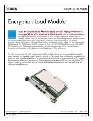
By utilizing Software Defined Networking (<strong>SDN</strong>), it becomes possible to address these<br />
needs using a more dynamic and flexible networking architecture. <strong>SDN</strong> moves away<br />
from traditional architecture and to a revolutionary service delivery platform that can<br />
easily and readily address the changes in industry. With <strong>SDN</strong>, the control plane is<br />
accessed and modified using open protocols through software clients. By allowing third<br />
parties increased access to the control plane via software, <strong>SDN</strong> provides enterprises<br />
and carriers unparalleled programmability and network flexibility with rapid<br />
experimentation and optimization in order to address business needs.<br />
Current Networking Systems<br />
PN 915-2635-01 Rev A December 2012 1
Introduction – Software Defined Networking<br />
Software Defined Networking System<br />
(Images source: Open Networking Foundation)<br />
<strong>OpenFlow</strong><br />
<strong>OpenFlow</strong> is one such communication protocol that enables <strong>SDN</strong>. <strong>OpenFlow</strong>, the first<br />
standard interface communications protocol designed specifically for <strong>SDN</strong>, decouples<br />
the control and data planes so that software can determine the network packets<br />
passing through a network thereby customizing the needs of applications and its users.<br />
With the centralization of the control plane, it is possible to introduce and experiment<br />
with new capabilities in isolated slices of the network without affecting the rest of the<br />
network. This major change in network architecture offers its users a way to introduce<br />
new applications without the reliance upon individual device configuration and vendor<br />
releases.<br />
<strong>SDN</strong> via <strong>OpenFlow</strong> revolutionizes and expands the capabilities of networking<br />
architecture, providing key benefits for the ever-changing market. With rapid<br />
innovation and experimentation possible through software control, <strong>OpenFlow</strong> delivers<br />
the flexibility necessary to combat current and future network problems. Additionally,<br />
not only is there an increased choice regarding new applications but there is also an<br />
increased choice regarding vendor markets. The switch from a hardware-based to a<br />
PN 915-2635-01 Rev A December 2012 2
Introduction – Software Defined Networking<br />
software-based networking architecture creates open multivendor markets as the<br />
network operator can select different control and data plane vendors. The division of<br />
the planes increases network reliability and security, creating the potential to lower<br />
both CAPEX and OPEX costs while decreasing the complexity of networking hardware<br />
and network management.<br />
<strong>OpenFlow</strong> Basic<br />
<strong>OpenFlow</strong> defines two main device types; a controller and a switch. The <strong>OpenFlow</strong><br />
controller talks to each <strong>OpenFlow</strong> switch over an IP connection (known as OF Channel)<br />
and has the ability to program the forwarding table of the switch with flow-table entries.<br />
These Flow Table entries are called Flows. A Flow has set of match fields and related<br />
actions. A match fields define the packet match criteria for the switch. Match fields are<br />
various protocol fields such as L2 MAC address, L3 IP address, VLAN address, etc. For<br />
each set of Match, there is a corresponding Action associated with it. The action<br />
defines what the switch supposed to do when packets matches the Match criteria. An<br />
Action could set certain protocol fields such as VLAN address and/or forward the<br />
packet to a port. A port could be a physical port or it could be virtual port number to<br />
identify an operation such as flood.<br />
PN 915-2635-01 Rev A December 2012 3
Introduction – Software Defined Networking<br />
When a packet enters a switch, the switch performs match criteria on the packet by<br />
looking up its Flow Table. When a packet matches a Flow table entry, switch performs a<br />
corresponding match associated with that flow entry. Please note that not all the<br />
match fields need to be defined. A wildcard is used to match for all the values for a<br />
certain match field. Along with match and action, a flow entry also has stats counter.<br />
The counters indicated the packet count for each flows.<br />
PN 915-2635-01 Rev A December 2012 4
Introduction – Software Defined Networking<br />
The <strong>SDN</strong> applications run on top of the <strong>OpenFlow</strong> controller using a well-defined API,<br />
known as the north-bound API. Each controller vendor provides their own set of APIs.<br />
Applications can range from layer 2 or layer 3 learning networks to static provisioned<br />
networks and can be as simple or complicated as the requirements demand. New<br />
applications are being developed every day to address challenges in the data center,<br />
service provider WAN, enterprise and other networks.<br />
PN 915-2635-01 Rev A December 2012 5
Test Case: <strong>OpenFlow</strong> Switch Setup and Functional Test<br />
Test Case: <strong>OpenFlow</strong> Switch Setup and Functional Test<br />
Overview<br />
One of the most important aspects of <strong>OpenFlow</strong> protocol is to create OF Channel. OF<br />
Channel establishes connection between the controller and switch using TCP or TLS.<br />
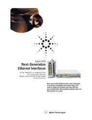
After the TCP session is established, controller and switch exchanges an OFPT_Hello<br />
message. The version field in the message is set to the highest <strong>OpenFlow</strong> protocol<br />
version supported by the sender. After receiving the message, the recipient calculates<br />
the <strong>OpenFlow</strong> protocol version to be used. The lowest version that is sent and received<br />
successfully is used as the <strong>OpenFlow</strong> protocol version.<br />
After version negotiation, the controller sends Features Request message and switch<br />
sends Features Reply message to advertise their capabilities. Then Echo Request and<br />
Echo Reply messages are exchanged to keep the OF Channel session alive between<br />
the controller and the switch.<br />
Ladder diagram<br />
The following diagram illustrates the message exchange between the switch and the<br />
controller.<br />
Figure 1: Message Exchange between Switch and Controller<br />
PN 915-2635-01 Rev A December 2012 7
Test Case: <strong>OpenFlow</strong> Switch Setup and Functional Test<br />
Objective<br />
The <strong>OpenFlow</strong> Switch Setup and Functional test verifies the functionality of <strong>OpenFlow</strong><br />
switches. The test provides basic guidelines on how to configure <strong>OpenFlow</strong> controller,<br />
establish OF Channel, and retrieve switch capabilities using learned information. The<br />
test also trigger stat request using on demand message function and verifies that switch<br />
sends reply with requested information. At the end of the test, statistics are reviewed.<br />
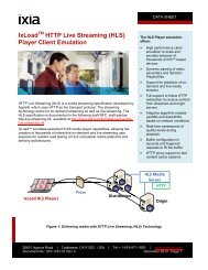
Setup<br />
The following figure illustrates the test setup.<br />
Figure 2: Test Setup – <strong>OpenFlow</strong> Switch Setup and Functional Test, test setup<br />
PN 915-2635-01 Rev A December 2012 8
Test Case: <strong>OpenFlow</strong> Switch Setup and Functional Test<br />
Step by Step Instructions<br />
The following steps describe the procedure for performing the test.<br />
1. Reserve one <strong>Ixia</strong> port<br />
Figure 3: Port Selection window<br />
2. Enable <strong>OpenFlow</strong> by selecting the <strong>OpenFlow</strong> check box in the RoutingSwitching<br />
tab in the Protocols window.<br />
Figure 4: RoutinSwitching tab, Protocols window<br />
PN 915-2635-01 Rev A December 2012 9
Test Case: <strong>OpenFlow</strong> Switch Setup and Functional Test<br />
3. Configure the emulated controller IP address and Gateway address from the<br />
Connected Interface tab on the Protocol Interfaces window. Use the IP address<br />
of the <strong>OpenFlow</strong> switch if you have only one switch. For Of Channel, ensure that<br />
ARP is resolved.<br />
Figure 5: Protocol Interfaces window<br />
4. Define the port role by selecting the role from the Port Role list on the Ports tab on<br />
the <strong>OpenFlow</strong> window. You can select any of the following port roles:<br />
a. Control: <strong>Ixia</strong> port will only act as a Controller.<br />
b. Traffic: <strong>Ixia</strong> port will be used as traffic endpoints.<br />
c. Control & In-Band Traffic: <strong>Ixia</strong> port will act as emulated controller as well as<br />
traffic endpoints (that is, in-band signaling).<br />
Figure 6: Ports tab, <strong>OpenFlow</strong> window<br />
PN 915-2635-01 Rev A December 2012 10
Test Case: <strong>OpenFlow</strong> Switch Setup and Functional Test<br />
5. Configure the Number of Interfaces by going to the Devices tab on the<br />
<strong>OpenFlow</strong> window. The number of interfaces should be equal to the number of<br />
emulated NICs of a controller.<br />
Figure 7: Devices tab, <strong>OpenFlow</strong> window<br />
6. Go to the Interface tab of the <strong>OpenFlow</strong> window and assign the Protocol<br />
Interfaces that you created on the Protocol Interface window. This interface is<br />
used for the control-plane (OF Channel). Configure Number of Channels as 1.<br />
Figure 8: Interfaces tab, <strong>OpenFlow</strong> window<br />
Following are some of the important parameters available on the Interface tab of<br />
the <strong>OpenFlow</strong> window:<br />
• Periodic Echo: Used to keep OF Channel session alive<br />
• Mode of Connection: Used to indicate whether <strong>Ixia</strong> port initiates TCP<br />
connection. The available options are Passive and Active. Passive is<br />
selected by default and it indicates that the <strong>Ixia</strong> port will not initiate the<br />
TCP connection. Active indicates that the <strong>Ixia</strong> port will be used to initiate<br />
the TCP connection.<br />
PN 915-2635-01 Rev A December 2012 11
Test Case: <strong>OpenFlow</strong> Switch Setup and Functional Test<br />
• TCP Port: Indicates the port is used to setup OF Channel. The default is<br />
6633.<br />
• Delete all Flow at Startup: Used to ensure that the switch does not have<br />
any pre-installed flow in its table. If this check box is selected, <strong>Ixia</strong><br />
emulated controller will send Flow Delete message with all 12 Tuples set as<br />
wildcard (*) after the OF Channel is up. And the test starts with no preinstalled<br />
flows.<br />
Figure 9: Interface tab, <strong>OpenFlow</strong> window parameters<br />
7. Go to the OF Channels tab on the Controller window and enable OF Channel by<br />
selecting the Enable check box. Also, enter the DUT IP address in the Remote IP<br />
field. The IP address that you enter in the Remote IP field is the IP address of the<br />
<strong>OpenFlow</strong> switch.<br />
Figure 10: OF Channels tab, Controller window<br />
PN 915-2635-01 Rev A December 2012 12
Test Case: <strong>OpenFlow</strong> Switch Setup and Functional Test<br />
9. Enable control capture by selecting the Control Enable check box on the<br />
Captures window. Also, start capture using the Capture control on the ribbon.<br />
Figure 11: Captures window<br />
10. Start <strong>OpenFlow</strong> protocol from the Protocols control on the ribbon.<br />
Figure 12: <strong>OpenFlow</strong> window<br />
PN 915-2635-01 Rev A December 2012 13
Test Case: <strong>OpenFlow</strong> Switch Setup and Functional Test<br />
Result Analysis<br />
The test results are available on the <strong>OpenFlow</strong> Controller Aggregated Statistics tab.<br />
Figure 13: <strong>OpenFlow</strong> Controller Aggregated Statistics tab<br />
This Statistics tab shows detailed information on <strong>OpenFlow</strong> connection status, message<br />
exchange, error condition, and packet_ins.<br />
You can verify the following statistics to analyze the OF Channel connection:<br />
OF Channel Configured<br />
OF Channel Configured<br />
UP<br />
OF Channel Learned UP<br />
Displays number configured OF Channel<br />
This statistics displays status of the configured OF Channel<br />
By default <strong>Ixia</strong> emulated controller accepts OF Channel<br />
connection from a switch even if it is not configured. This<br />
statistics shows the un-configured OF Channel.<br />
Note: The Configure OF Channels option under Learned<br />
Information allows configuring the learned OF Channel.<br />
OF Channel flap count<br />
Hello Tx/Rx<br />
Echo request Tx/Rx<br />
This statistics shows the number of times the TCP session is<br />
reset.<br />
This statistics displays hello message exchange.<br />
This statistics displays echo message for the liveliness between<br />
the switch and controller.<br />
In case the <strong>OpenFlow</strong> Controller Aggregated Statistics tab is not available you need to<br />
enable it from the Select Views window.<br />
PN 915-2635-01 Rev A December 2012 14
Test Case: <strong>OpenFlow</strong> Switch Setup and Functional Test<br />
To enable the <strong>OpenFlow</strong> Controller Aggregated Statistics tab, click Select Views and<br />
select <strong>OpenFlow</strong> Controller Aggregated Statistics check box as shown in the following<br />
figure.<br />
Figure 14: Select Views window<br />
Go to Capture Analyzer and click on Ladder Diagram to verify message exchange<br />
between the controller and the switch.<br />
Figure 15: Capture Analyzer, Ladder Diagram tab<br />
To verify the switch capabilities, supported action or any error condition, go to<br />
Learned Information window. The Learned Information window contains several tabs<br />
PN 915-2635-01 Rev A December 2012 15
Test Case: <strong>OpenFlow</strong> Switch Setup and Functional Test<br />
as shown in the figure below.. Click Refresh button on the ribbon to update this<br />
information.<br />
The OF Channel Learned Info tab, contains multiple panes. Left pane displays OF<br />
Channel information including TCP port, Data Path ID, Reply State and any error<br />
message received from the switch. When you select a row (OF Channel), the right<br />
pane displays all <strong>OpenFlow</strong> enabled ports information on that switch.<br />
Figure 16: OF Channel Learned Info tab, Learned Info window<br />
The Ports Stat view displays the details of each <strong>OpenFlow</strong> ports of the connected<br />
switch.<br />
Various <strong>OpenFlow</strong> message can be sent from controller using On Demand Message<br />
button on the ribbon. Select the OF Channel and then click On Demand Message<br />
button. On the Open Flow Learned Info Trigger Settings window, select the Port Stat<br />
check box (Multiple stats request can be sent) and click OK.<br />
PN 915-2635-01 Rev A December 2012 16
Test Case: <strong>OpenFlow</strong> Switch Setup and Functional Test<br />
Figure 17: Open Flow Learned Info Trigger Settings window<br />
This feature allows you to monitor the switch status without logging on to the switch. In<br />
this example, you can view <strong>OpenFlow</strong> switch ports information like Tx and Rx packet<br />
counts, dropped packet, CRC, Frame alignment, Collision and Overrun errors. The<br />
Latency field shows the response time of the switch for the particular stat request.<br />
Figure 18: Port Stats tab showing <strong>OpenFlow</strong> switch ports information<br />
Troubleshooting<br />
Use following steps to troubleshoot any OF Channel issues:<br />
• Enure ARP is resolved under Protocol Interface. Also try to PING emulated<br />
controller IP (<strong>Ixia</strong>) from <strong>OpenFlow</strong> switch.<br />
• You can enable protocol trace from the trace window.<br />
PN 915-2635-01 Rev A December 2012 17
Test Case: <strong>OpenFlow</strong> Switch Setup and Functional Test<br />
To open the trace window, right-click on Controller Interface and then click Open<br />
Trace Window.<br />
On the trace window select the OPEN FLOW check box and then select the debug<br />
level from the list and click OK.<br />
PN 915-2635-01 Rev A December 2012 18
Test Case: <strong>OpenFlow</strong> Switch Setup and Functional Test<br />
1. IxNetwork Analyzer can decode <strong>OpenFlow</strong> messages. Use Control plane<br />
capture to see bi-directional communication in real-time (Note - It requires<br />
Analyzer Chassis component license). Using this trace, you can determine<br />
whether bi-directional communication is happening properly as per ladder<br />
diagram shown earlier.<br />
Conclusions<br />
By validating the statistics and control plane message exchanges using the features<br />
above, we have verified that the DUT can successfully establish OF Channel, keep the<br />
session alive and respond to Stats Request from the controller.<br />
PN 915-2635-01 Rev A December 2012 19
Test Case: <strong>OpenFlow</strong> Switch Forwarding Test<br />
Test Case: <strong>OpenFlow</strong> Switch Forwarding Test<br />
Overview<br />
Through <strong>OpenFlow</strong> you can program data path by building the flow table in <strong>OpenFlow</strong><br />
switch. In the flow table there are two components: Match and One or more Actions.<br />
<strong>OpenFlow</strong> 1.0 specification covers 12 tuple matches as shown below.<br />
After the match, certain actions can be performed, such as forward packet to zero or<br />
more ports, modify the field, drop the packet or if no match found forward it to<br />
controller.<br />
Objective<br />
The objective of this test is to verify the ability of the <strong>OpenFlow</strong> switch to forward L2<br />
traffic. The DUT should be able to look up the Flow Table when L2 traffic is received and<br />
forward the traffic based on specified actions. In this test, initially controller will push<br />
down L2 flows with certain Match and Action parameters. Then using traffic wizard,<br />
matching traffic will be created and sent. Using the traffic statistics; switch forwarding<br />
performance will be verified.<br />
PN 915-2635-01 Rev A December 2012 21
Test Case: <strong>OpenFlow</strong> Switch Forwarding Test<br />
Setup<br />
The following figure illustrates the test setup:<br />
Figure 19: <strong>OpenFlow</strong> Switch Forwarding Test, test setup<br />
PN 915-2635-01 Rev A December 2012 22
Test Case: <strong>OpenFlow</strong> Switch Forwarding Test<br />
Step by Step Instructions<br />
The following steps describe the procedure for performing the test.<br />
1. Reserve 3 <strong>Ixia</strong> ports (1 for controller and 2 port traffic endpoints)<br />
Figure 20: Port Selection window<br />
2. Enable <strong>OpenFlow</strong> on all the ports by selecting the <strong>OpenFlow</strong> check box on the<br />
Protocols window.<br />
Figure 21: RoutingSwitching tab, Protocols window<br />
PN 915-2635-01 Rev A December 2012 23
Test Case: <strong>OpenFlow</strong> Switch Forwarding Test<br />
3. Configure the emulated controller IP address and Gateway address from the<br />
Connected Interface tab on the Protocol Interfaces window. Use the IP address<br />
of the <strong>OpenFlow</strong> switch if you have only one switch. For Of Channel, ensure that<br />
ARP is resolved. You do not have to configure anything on host port.<br />
Figure 22: Connected Interfaces tab, Protocol Interface window<br />
4. Define the port role by selecting the role from the Port Role list on the Ports tab on<br />
the <strong>OpenFlow</strong> window. You can select any of the following port roles:<br />
a. Control: for Controller port<br />
b. Traffic: for host ports<br />
PN 915-2635-01 Rev A December 2012 24
Test Case: <strong>OpenFlow</strong> Switch Forwarding Test<br />
5. Configure the Number of Interfaces as 1, by going to the Devices tab on the<br />
<strong>OpenFlow</strong> window. The number of interfaces should be equal to the number of<br />
emulated NICs of a controller.<br />
Figure 23: Device tab, <strong>OpenFlow</strong> window<br />
6. Go to the Interface tab of the <strong>OpenFlow</strong> window and assign the Protocol<br />
Interfaces that you created on the Protocol Interface window. This interface is<br />
used for the control-plane (OF Channel). Configure Number of Channels as 1.<br />
Figure 24: Interfaces tab, <strong>OpenFlow</strong> window<br />
PN 915-2635-01 Rev A December 2012 25
Test Case: <strong>OpenFlow</strong> Switch Forwarding Test<br />
7. Go to OF Channels tab and enter DUT IP address in Remote IP field. Change flow<br />
range count to 2.<br />
Figure 25: OF Channel tab, <strong>OpenFlow</strong> window<br />
8. In the Flow Range tab, create 5 flows on each range. Enter Source/Destination MAC<br />
and VLAN-ID. For remaining all field use wild card value (*). This means, Switch will<br />
make forwarding decision based on matching Src/Dst MAC address and VLAN-ID.<br />
Configure correct In Port field with the switch port number that is connected to <strong>Ixia</strong><br />
host port generating traffic.<br />
Figure 26: FlowRanges tab, <strong>OpenFlow</strong> window<br />
PN 915-2635-01 Rev A December 2012 26
Test Case: <strong>OpenFlow</strong> Switch Forwarding Test<br />
9. Use Configure Range button (…) to increment MAC and VLAN<br />
10. Now create Number of Action from Config tab.<br />
PN 915-2635-01 Rev A December 2012 27
Test Case: <strong>OpenFlow</strong> Switch Forwarding Test<br />
11. Go to Actions tab and select Action Type as OutPut and Output Port Type as<br />
Custom/Manual. Enter the Output Port value of the switch where the traffic will<br />
be forwarded to.<br />
Figure 27: Actions tab<br />
PN 915-2635-01 Rev A December 2012 28
Test Case: <strong>OpenFlow</strong> Switch Forwarding Test<br />
12. Use the <strong>OpenFlow</strong> control on the ribbon to start <strong>OpenFlow</strong> protocol and make<br />
sure OF Channel comes up. The value of the OF Channel Configured UP field<br />
indicates that the OF Channel is up.<br />
Figure 28: Controller Running, showing OF Channel Configured Up<br />
To verify the switch capabilities, supported action or any error condition, go to<br />
Learned Information window. Several tabs are available as shown in the following<br />
figure. Click Refresh button on the ribbon to update the information.<br />
Go to OF Channel learned Info tab, It has two panes. Left pane displays OF<br />
Channel information including TCP Port, Data Path ID, Reply State and any error<br />
message received from the Switch. When you select a row (OF Channel), the right<br />
pane displays all <strong>OpenFlow</strong> enabled ports information on that switch.<br />
Figure 29: Learned Information window<br />
PN 915-2635-01 Rev A December 2012 29
Test Case: <strong>OpenFlow</strong> Switch Forwarding Test<br />
13. From OF Channel Learned Info tab use On Demand Messages button to request<br />
switch to send flow table information.<br />
Figure 30: <strong>OpenFlow</strong> Learned Info Trigger Settings window<br />
To verify flow table information, go to Flow Stat tab. On this tab, make sure that<br />
switch has correct flow entries to match the fields defined earlier in the flow range,<br />
input port and wild card entry for non-matching field.<br />
Figure 31: Flow Stat tab, Learned Information window<br />
PN 915-2635-01 Rev A December 2012 30
Test Case: <strong>OpenFlow</strong> Switch Forwarding Test<br />
14. Create Traffic endpoints on host ports using Generate Traffic Endpoint wizard. This<br />
option will be available from Flow Ranges tab.<br />
Figure 32: Flow Ranges tab<br />
15. The following steps will help you use the <strong>OpenFlow</strong> Traffic Converter Wizard to<br />
create the corresponding traffic end points for the Flow Range values on <strong>Ixia</strong><br />
ports.<br />
a. Select host ports where Traffic Endpoints will be created and click next.<br />
Figure 33: <strong>OpenFlow</strong> Traffic Converter Wizard<br />
b. Enable Flow Ranges to be included for traffic endpoints<br />
PN 915-2635-01 Rev A December 2012 31
Test Case: <strong>OpenFlow</strong> Switch Forwarding Test<br />
c. Map the Traffic source port, Host-1 in following figure with DUT In port. This<br />
will enable IxNetwork to map the traffic ports to switch ports.<br />
d. Map Traffic destination port, Host-2 in following figure with DUT Out port.<br />
This will enable IxNetwork to map the traffic ports to switch ports.<br />
e. Leave everything default on next two windows.<br />
f. Select Generate and Overwrite Existing Configuration option to remove<br />
previously generated traffic endpoint. Click Finish to complete the wizard<br />
configuration.<br />
PN 915-2635-01 Rev A December 2012 32
Test Case: <strong>OpenFlow</strong> Switch Forwarding Test<br />
g. Go to each host port and make sure the wizard has generated correct<br />
traffic endpoint.<br />
16. Go to Traffic Wizard to create traffic flow between Host-1 and Host-2<br />
a. Select Traffic from the tree and click on Add L2-3 Traffic button in the<br />
ribbon. It opens the Advance Traffic Wizard.<br />
Figure 34: Advanced Traffic Wizard<br />
PN 915-2635-01 Rev A December 2012 33
Test Case: <strong>OpenFlow</strong> Switch Forwarding Test<br />
b. Select Type of Traffic as Ethernet/VLAN and use <strong>OpenFlow</strong> encapsulation<br />
filter for Source and Destination endpoints.<br />
c. Select source and destination endpoint and click Next.<br />
Figure 35: Advanced Traffic Wizard, Source and Destination Endpoints<br />
PN 915-2635-01 Rev A December 2012 34
Test Case: <strong>OpenFlow</strong> Switch Forwarding Test<br />
d. Leave default values for Packet/QoS, Flow Group setup and Frame Setup<br />
page.<br />
e. Set the desired traffic load on Rate Setup page and click Next.<br />
PN 915-2635-01 Rev A December 2012 35
Test Case: <strong>OpenFlow</strong> Switch Forwarding Test<br />
f. On Flow Tracking page, enable Source/Dest Value Pair tracking option.<br />
Click Next.<br />
PN 915-2635-01 Rev A December 2012 36
Test Case: <strong>OpenFlow</strong> Switch Forwarding Test<br />
g. Skip ‘Protocol Behaviors window and go to Preview window to view how<br />
the traffic flow will look like and click Finish button to end traffic wizard.<br />
PN 915-2635-01 Rev A December 2012 37
Test Case: <strong>OpenFlow</strong> Switch Forwarding Test<br />
17. Click L2-3 Traffic button to push the traffic on port and start traffic.<br />
Results Analysis<br />
• On Traffic Item Statistics verify that traffic is flowing through the switch without<br />
packet loss.<br />
Figure 36: Traffic Item Statistics view<br />
Select the Traffic Item and Right click on it. Select drill down per<br />
Source/Destination Value Pair tracking option. This drill down view will display<br />
traffic statistics per individual source and destination MAC address.<br />
PN 915-2635-01 Rev A December 2012 38
Test Case: <strong>OpenFlow</strong> Switch Forwarding Test<br />
• Make policy change on controller and push it to the switch and verify that<br />
switch changes packet forwarding decision according to the rule set by the<br />
controller.<br />
Leave traffic and <strong>OpenFlow</strong> protocol in Running state. Go to <strong>OpenFlow</strong><br />
Controller Flow Range and clear the second flow range.<br />
Ensure following MAC address and VLAN stops receiving traffic. Go to traffic<br />
statistics to verify this functionality.<br />
PN 915-2635-01 Rev A December 2012 39
Test Case: <strong>OpenFlow</strong> Switch Forwarding Test<br />
PN 915-2635-01 Rev A December 2012 40
Test Case: <strong>OpenFlow</strong> Switch Forwarding Test<br />
• Select the flow range again and see if switch starts forwarding traffic for that<br />
MAC/VLAN again.<br />
Conclusions<br />
This test case can be used to verify:<br />
• Switch installs correct flow entries in its flow table as pushed by the controller.<br />
• It makes packet forwarding decision as per the rule set by the controller.<br />
• It complies to one or more action set by the controller.<br />
Test Variables<br />
The following variables can be used to verify the behavior of an <strong>OpenFlow</strong> Switch.<br />
1. L3 Forwarding Test<br />
Set the matching criteria on L3 header field such as Source IP, Destination IP and<br />
DSCP value<br />
2. Use multiple Actions<br />
PN 915-2635-01 Rev A December 2012 41
Test Case: <strong>OpenFlow</strong> Switch Forwarding Test<br />
Apply multiple actions for each Flow range. Use one of the following actions along<br />
with Output and verify that switch correctly performs multiple actions on the<br />
packets.<br />
Set VLAN ID<br />
Strip VLAN Header<br />
Set Ethernet Src/Dst.<br />
Set IP DSCP<br />
Set IPv4 Src/Dst.<br />
Set Transport Src/Dst.<br />
Add or Change VLAN ID for matching flow<br />
Strip the VLAN header from the matching flow<br />
Change source/destination MAC for matching flow<br />
Change DSCP value for matching flow<br />
Change IP address for matching flow<br />
Change TCP/UDP port<br />
PN 915-2635-01 Rev A December 2012 42
Test Case: Switch Flow Failover Performance Test<br />
Test Case: Switch Flow Failover Performance Test<br />
Overview<br />
Networking infrastructure has become key component for any business. Today’s<br />
networks carries Voice, Data and Video traffic over the same network infrastructure.<br />
Even the few seconds outage can cause huge impact on the business. Therefore<br />
networks are designed with redundant links to minimize the downtime and increase the<br />
reliability. The key challenge for any networking device is to be able to detect the<br />
failure and forward traffic to redundant path without affecting application traffic<br />
performance.<br />
Objective<br />
The objective of this test case is to verify Switch performance to handle convergence in<br />
the network and ability to converge the traffic to secondary path without affecting<br />
traffic forwarding performance. For this test, <strong>Ixia</strong>’s unique TrueView convergence test<br />
methodology will be used to measure the data plane to data plane convergence time<br />
of the switch.<br />
TrueView convergence test provides the following measurements:<br />
• Timestamp of every packet<br />
• Timestamp the first packet in and last packet out on a port per flow<br />
• Ability to capture protocol event timestamp<br />
• Ability to capture link event timestamp<br />
• Ability to monitor receive rate and timestamp when "Below" thresholds are crossed<br />
• Ability to monitor receive rate and timestamp when "Above" thresholds are crossed<br />
• Ability to timestamp link event (up/down)<br />
PN 915-2635-01 Rev A December 2012 43
Test Case: Switch Flow Failover Performance Test<br />
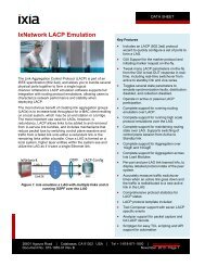
The diagram below shows, when traffic drops below threshold value on primary path<br />
(Blue line), it will latch tDP-below1 timestamp and when traffic reaches above threshold<br />
value on a secondary path (Red line), it will latch tDP-above2 timestamp. This<br />
timestamp will give data plane convergence time.<br />
DP-DP Convergence time = tDP Above timestamp – tDP Below timestamp<br />
Figure 37: CP/DP Convergence Time, calculation<br />
PN 915-2635-01 Rev A December 2012 44
Test Case: Switch Flow Failover Performance Test<br />
Setup<br />
Figure 38: Switch Flow Failover Performance Test, test setup<br />
Step by Step instructions<br />
1. Reserve 4 <strong>Ixia</strong> port (1 for controller and 3 for data plane traffic)<br />
Figure 39: Port Selection window<br />
PN 915-2635-01 Rev A December 2012 45
Test Case: Switch Flow Failover Performance Test<br />
2. Enable <strong>OpenFlow</strong> on all 4 ports by selecting the <strong>OpenFlow</strong> check box on the<br />
RoutingSwitching tab on the Protocols window.<br />
Figure 40: RoutingSwitching tab, Protocols window<br />
3. Go to Connected Interface tab to configure Emulated Controller IP Address and<br />
Gateway Address.<br />
Use <strong>OpenFlow</strong> switch’s IP address if you have only one switch. Ensure that ARP is<br />
resolved for for OF Channel. Do not configure anything on host ports.<br />
Figure 41: Connected Interface tab<br />
PN 915-2635-01 Rev A December 2012 46
Test Case: Switch Flow Failover Performance Test<br />
4. Go to Ports tab and select the Port Role.<br />
You can select any of the following:<br />
a. Control: for Controller port<br />
b. Traffic: for host ports<br />
Figure 42: Ports Tab<br />
5. Go to Devices tab and configure Number Of Interfaces as 1. The number of<br />
interfaces equals the number of emulated NICs of a controller.<br />
Figure 43: Devices tab<br />
PN 915-2635-01 Rev A December 2012 47
Test Case: Switch Flow Failover Performance Test<br />
6. Go to Interfacees tab and assign the interface previously created under<br />
protocol interface. This interface is used for the control-plane (OF Channel).<br />
Configure Number of Channels as 1.<br />
7. Go to OF Channels tab and enter DUT IP address in Remote IP field. Enter<br />
Number of Flow Ranges as 2.<br />
8. Under Flow Ranges tab, configure Ethernet Type, Source and Destination IP<br />
address. Use wild card (*) for remaining all fields. Use same IP address for both<br />
ranges. Configure correct In Port field with the switch port number that is<br />
connected to <strong>Ixia</strong> host port generating traffic.<br />
Figure 44: Flow Ranges tab<br />
PN 915-2635-01 Rev A December 2012 48
Test Case: Switch Flow Failover Performance Test<br />
9. Create Number of Action from config tab. Change Match Type to Strict and<br />
Priority value for both flows. The flow with higher priority value gets forwarded<br />
first.<br />
Figure 45: Flow Ranges tab (2),<br />
10. Go to Actions tab and select Action Type as OutPut and Output Port Type as<br />
Custom/Manual. Enter the ‘Output Port’ value of the switch where the traffic will<br />
be forwarded to.<br />
Figure 46: Actions tab<br />
PN 915-2635-01 Rev A December 2012 49
Test Case: Switch Flow Failover Performance Test<br />
11. Start <strong>OpenFlow</strong> protocol using the <strong>OpenFlow</strong> control on the ribbon, and make<br />
sure OF Channel comes up.<br />
Figure 47: Controller Running window<br />
To verify the switch capabilities, supported action or any error condition, go to<br />
Learned Information window. Several tabs as shown in below figure are available on<br />
this window. Click Refresh button in the ribbon to update this information. Go to OF<br />
Channel Learned Info tab. It displays several panes. The left pane displays OF<br />
Channel information including TCP port, Data path ID, Reply state and any error<br />
message received from the Switch. When you select a row (OF Channel), the right<br />
pane displays all <strong>OpenFlow</strong> enabled ports information on that switch.<br />
Figure 48: OF Channel Learned Info<br />
PN 915-2635-01 Rev A December 2012 50
Test Case: Switch Flow Failover Performance Test<br />
From OF Channel Learned Info tab use On Demand Messages button to request<br />
switch to send flow table information.<br />
Figure 49: <strong>OpenFlow</strong> Learned Info Trigger Settings window<br />
To verify flow table information, go to Flow Stat tab and ensure that switch has<br />
correct flow entries to match the fields defined earlier in the flow range. Enter port<br />
and wild card entry for non-matching field.<br />
PN 915-2635-01 Rev A December 2012 51
Test Case: Switch Flow Failover Performance Test<br />
Create Traffic endpoints on host ports using the Generate Traffic Endpoint wizard. This<br />
option is available on the Flow Ranges tab.<br />
Figure 50: Flow Ranges tab<br />
The following steps will help you use the <strong>OpenFlow</strong> Traffic Converter Wizard. This will<br />
create the corresponding traffic end points for the Flow Range values on <strong>Ixia</strong> ports.<br />
a. Select host ports where Traffic Endpoints will be created and click Next.<br />
Figure 51: <strong>OpenFlow</strong> Traffic Converter Wizard – Port Select – Name window<br />
b. Select both Primary/Secondary flow range to be included in traffic.<br />
Figure 52: <strong>OpenFlow</strong> Traffic Converter Wizard – Select Flow Ranges - Name<br />
c. Map the Traffic source port in the following figure Host-1, with DUT In port.<br />
PN 915-2635-01 Rev A December 2012 52
Test Case: Switch Flow Failover Performance Test<br />
This will enable IxNetwork to map the traffic ports to switch ports<br />
Figure 53: <strong>OpenFlow</strong> Traffic Concerter Wizard – DUT In Port To <strong>Ixia</strong> Port Mapping – Name window<br />
d. Map traffic receiving ports with DUT’s output port.<br />
This will enable IxNetwork to map the traffic ports to switch ports<br />
Figure 54: <strong>OpenFlow</strong> Traffic Converter Wizard – DUT Out Port To <strong>Ixia</strong> Port Mapping – Name window<br />
a. Leave everything default on next two windows.<br />
b. Select Generate and Overwrite Existing Configuration check box to<br />
remove previously generated traffic endpoint and click on finish.<br />
Figure 55: <strong>OpenFlow</strong> Traffic Converter Wizard – Name window<br />
PN 915-2635-01 Rev A December 2012 53
Test Case: Switch Flow Failover Performance Test<br />
c. Go to each host port and ensure the wizard has generated correct traffic<br />
endpoint<br />
PN 915-2635-01 Rev A December 2012 54
Test Case: Switch Flow Failover Performance Test<br />
12. Go to Traffic Options window and select Data Plane Event Monitor check box<br />
and set desired data plane threshold limit.<br />
Figure 56: Traffic Options window<br />
PN 915-2635-01 Rev A December 2012 55
Test Case: Switch Flow Failover Performance Test<br />
13. Go to Traffic Wizard window to create traffic flow between Host-1 to Host-2 and<br />
Host-3.<br />
a. Select Traffic from the tree and click on Add L2-3 Traffic button in the<br />
ribbon. It will open Advance Traffic Wizard.<br />
Figure 57: Advanced Traffic Wizard<br />
PN 915-2635-01 Rev A December 2012 56
Test Case: Switch Flow Failover Performance Test<br />
b. Select Type of Traffic as IPv4and use <strong>OpenFlow</strong> encapsulation filter for<br />
Source and Destination endpoints.<br />
Figure 58: Advanced Traffic Wizard, Endpoints window<br />
PN 915-2635-01 Rev A December 2012 57
Test Case: Switch Flow Failover Performance Test<br />
c. Select Host-1 as traffic source and Host-2 and Host-3 as traffic destination.<br />
Make sure the Merge Destination Range check box is selected. This<br />
ensures that unique flow is created based on destination IP address.<br />
Figure 59: Advanced Traffic Wizard, Source/Destination Endpoints mapping<br />
d. Leave default values on Packet/QoS, Flow group setup, and frame setup<br />
windows.<br />
PN 915-2635-01 Rev A December 2012 58
Test Case: Switch Flow Failover Performance Test<br />
e. Set the desired traffic load on Rate Setup window and click Next.<br />
Figure 60: Advanced Traffic Wizard, Rate Setup window<br />
PN 915-2635-01 Rev A December 2012 59
Test Case: Switch Flow Failover Performance Test<br />
f. On Flow Tracking window, select Source/Dest Value Pair and Dest<br />
Endpoint as tracking option. Click Next.<br />
Figure 61: Advanced Traffic Wizard, Flow Tracking window<br />
PN 915-2635-01 Rev A December 2012 60
Test Case: Switch Flow Failover Performance Test<br />
g. Skip Protocol Behaviors window and go to Preview window to view how<br />
the traffic flow looks like and click Finish button.<br />
Figure 62: Advanced Traffic Wizard, Preview window<br />
PN 915-2635-01 Rev A December 2012 61
Test Case: Switch Flow Failover Performance Test<br />
14. Click L2-3 Traffic button to push the traffic on port and start traffic.<br />
Result Analysis<br />
1. Verify that there is no traffic loss and traffic is flowing through the primary path<br />
(which has highest priority, as configured earlier) on the switch.<br />
PN 915-2635-01 Rev A December 2012 62
Test Case: Switch Flow Failover Performance Test<br />
2. While traffic is running, go to <strong>OpenFlow</strong> controller flow range and disable Primary<br />
flow. This sends Flow-Mod delete command to switch. Switch removes the<br />
Primary Flow entry and since there is only one flow entry in its Flow Table it will<br />
start forwarding packets out on the secondary path output port.<br />
3. Go to traffic Flow Statistics window and verify that the traffic gets switched over<br />
to secondary path towards host-3. And, go to Traffic Item Statistics tab to verify<br />
there is no traffic loss.<br />
4. From traffic item statistics view, perform drill down per destination endpoint (right<br />
click on traffic item, select drill down per destination option). This will create User<br />
Defined Statistics view tab. On this tab, you will notice DP/DP Convergence Time<br />
on far right hand side (you can move this column in the beginning by dragging<br />
the column header). This field provides data plane event convergence time in<br />
micro seconds.<br />
5. Go to Flow Statistics to monitor DP-Above and DP-Below timestamp (located in<br />
far right corner) to confirm DP/DP convergence time accuracy.<br />
DP-DP Convergence time = tDP-Above time stamp – tDP-Below timestamp<br />
PN 915-2635-01 Rev A December 2012 63
Test Case: Switch Flow Failover Performance Test<br />
6. Prior to next control plane trigger event, perform Clear CP/DP Convergence<br />
Statistics in order to get accurate results for the next convergence event on the<br />
switch.<br />
Conclusions<br />
This test allows you to validate DUT’s ability to detect the failure and switch traffic to<br />
alternate path as fast as possible without significant packet loss. It also provides<br />
accurate traffic convergence measurements.<br />
Variables<br />
1. TrueView convergence test also provides accurate measurement for control<br />
plane to data plane convergence time. In order to perform this test, user should<br />
select control plane events check box in step#17. All other steps remain the<br />
same.<br />
Go to Statistics view and track by destination endpoint, you should notice CP/DP<br />
convergence Time column.<br />
2. Same test can be repeated for various traffic rates, number of flows and<br />
threshold values.<br />
PN 915-2635-01 Rev A December 2012 64
Contact <strong>Ixia</strong><br />
Corporate Headquarters<br />
<strong>Ixia</strong> Worldwide Headquarters<br />
26601 W. Agoura Rd.<br />
Calabasas, CA 91302<br />
USA<br />
+1 877 FOR IXIA (877 367 4942)<br />
+1 818 871 1800 (International)<br />
(FAX) +1 818 871 1805<br />
sales@ixiacom.com<br />
EMEA <strong>Ixia</strong> Europe Limited<br />
One Globeside, Fieldhouse Lane<br />
Marlow, SL7 1HZ<br />
United Kingdom<br />
+44 1628 405750<br />
FAX +44 1628 405790<br />
salesemea@ixiacom.com<br />
Asia Pacific<br />
210 Middle Road<br />
#08-01 IOI Plaza<br />
Singapore 188994<br />
+65 6332 0126<br />
Support-Field-Asia-Pacific@ixiacom.com<br />
Japan <strong>Ixia</strong> KK<br />
Aioi Sampo Shinjuku Building, 16th Floor<br />
3-25-3 Yoyogi Shibuya-Ku<br />
Tokyo 151-0053<br />
Japan<br />
+81 3 5365 4690<br />
(FAX) +81 3 3299 6263<br />
ixiajapan@ixiacom.com<br />
<strong>Ixia</strong> India<br />
UMIYA Business Bay<br />
Tower – I, 7th Floor, Cessna Business Park<br />
Outer ring road (Marathalli- Sarjapur ring road)<br />
Kadubeesanahalli Village, Vartur Hobli<br />
Bangalore 560 037<br />
India<br />
+91 80 42862600<br />
Web site: www.ixiacom.com<br />
General: info@ixiacom.com<br />
Investor Relations: ir@ixiacom.com<br />
Training: training@ixiacom.com<br />
Support: support@ixiacom.com<br />
+1 877 367 4942<br />
+1 818 871 1800 Option 1 (outside USA)<br />
online support form:<br />
http://www.ixiacom.com/support/inquiry/<br />
Support: eurosupport@ixiacom.com<br />
+44 1628 405797<br />
online support form:<br />
http://www.ixiacom.com/support/inquiry/<br />
location=emea<br />
Support: Support-Field-Asia-<br />
Pacific@ixiacom.com<br />
+1 818 871 1800 (Option 1)<br />
online support form:<br />
http://www.ixiacom.com/support/inquiry/<br />
Support: support@ixiacom.com<br />
+81 3 5365 4690<br />
online support form:<br />
http://www.ixiacom.com/support/inquiry/<br />
Support: support-india@ixiacom.com<br />
+91 80 32918500<br />
online support form:<br />
http://www.ixiacom.com/support/inquiry/<br />
location=india<br />
PN 915-2635-01 Rev A December 2012 65
PN 915-2635-01 Rev A December 2012 66