Introduction - The Strand Archive
Introduction - The Strand Archive
Introduction - The Strand Archive

Create successful ePaper yourself
Turn your PDF publications into a flip-book with our unique Google optimized e-Paper software.
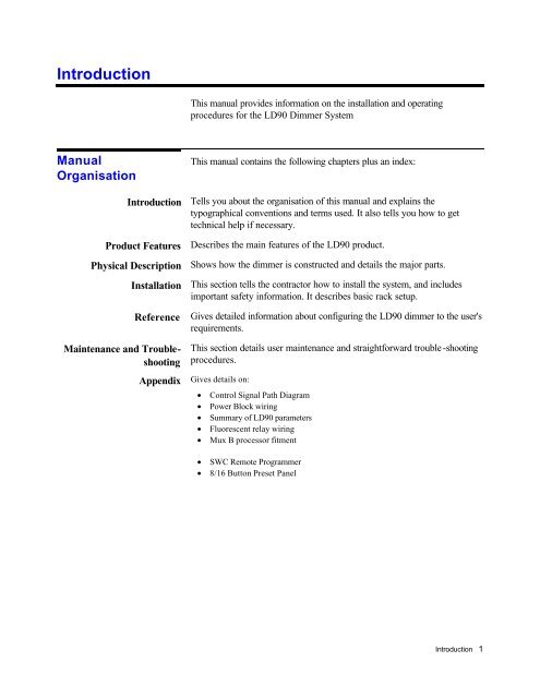
<strong>Introduction</strong><br />
This manual provides information on the installation and operating<br />
procedures for the LD90 Dimmer System<br />
Manual<br />
Organisation<br />
<strong>Introduction</strong><br />
Product Features<br />
Physical Description<br />
Installation<br />
Reference<br />
Maintenance and Troubleshooting<br />
Appendix<br />
This manual contains the following chapters plus an index:<br />
Tells you about the organisation of this manual and explains the<br />
typographical conventions and terms used. It also tells you how to get<br />
technical help if necessary.<br />
Describes the main features of the LD90 product.<br />
Shows how the dimmer is constructed and details the major parts.<br />
This section tells the contractor how to install the system, and includes<br />
important safety information. It describes basic rack setup.<br />
Gives detailed information about configuring the LD90 dimmer to the user's<br />
requirements.<br />
This section details user maintenance and straightforward trouble -shooting<br />
procedures.<br />
Gives details on:<br />
• Control Signal Path Diagram<br />
• Power Block wiring<br />
• Summary of LD90 parameters<br />
• Fluorescent relay wiring<br />
• Mux B processor fitment<br />
• SWC Remote Programmer<br />
• 8/16 Button Preset Panel<br />
<strong>Introduction</strong> 1
<strong>The</strong> LD90 Dimmer<br />
<strong>The</strong> LD90 is a fully digital, semi-modular dimmer, suitable for fixed<br />
installations. It is designed to give the user an affordable system with a high<br />
degree of flexibility.<br />
This is achieved by using the latest microprocessor technology together<br />
with sixty years of dimmer design and manufacturing experience for the<br />
entertainment industry.<br />
Standard features include simultaneous multiplex and analogue control<br />
signals, outputs to control auxiliary dimmers, multi-language configuration<br />
menus, diagnostic messages and the storage and playback of preset lighting<br />
scenes.<br />
<strong>The</strong> LD90 system offers a user-configurable mixture of dimmer ratings in<br />
one cabinet. Standard options include earth leakage circuit breakers<br />
(RCDs) and System Wide Control of all racks, using a Handheld<br />
Pragrammer, Preset Station, or Personal Computer.<br />
<strong>The</strong> LD90 offers these and many more features designed to give the user<br />
the greatest flexibility.<br />
2
Glossary and<br />
Abbreviations Default<br />
Dimmer Curve (Law)<br />
HTP<br />
Level<br />
Maximum O/P Voltage<br />
MUX<br />
<strong>The</strong> following terminology is used throughout this manual for consistency:<br />
<strong>The</strong> original factory settings.<br />
<strong>The</strong> relationship between a control level and actual dimmer output level.<br />
Highest Takes Precedence, whereby channel levels when combined will<br />
give priority to the one with the highest level.<br />
A numerical value used to express the 'brightness' of a dimmer. Usually<br />
shown as %.<br />
<strong>The</strong> maximum output voltage which may be set for each dimmer or group<br />
of dimmers.<br />
Abbreviation of the word Multiplex. Multiplex systems transmit data<br />
(usually dimmer information) from a lighting controller to a dimmer rack via<br />
means of a single signal cable. <strong>The</strong>re are various types of multiplex<br />
systems as shown below:<br />
• DMX 512: A USITT Standard system for digital transmission of a maximum<br />
512 dimmer levels.<br />
• D54: <strong>Strand</strong> Lighting multiplexed analogue system for transmission of 384<br />
dimmer levels.<br />
• SMX: A lighting standard for digital transmission including error checking<br />
and recovery.<br />
No MUX State<br />
Name (Circuit Identifier)<br />
NON-DIM<br />
Patch<br />
Phase<br />
This defines which of the 99 preset states (or blackout) dimmers should<br />
fade to when the both the A & B mux inputs have failed. State 0 is fixed<br />
and is always blackout (the default), the other 99 states are user<br />
programmable.<br />
<strong>The</strong> Name is a unique identification string containing up to five upper case<br />
letters or numbers which you can assign to each dimmer. <strong>The</strong> dimmer<br />
number may be the same as the Name, or may be a string used to indicate<br />
circuit location, phase, etc. This feature is useful for SWC or SV90.<br />
A mode in which the dimmer circuit responds to its control signal as a<br />
switch.<br />
A way of allocating a logical dimmer to a multiplex signal address.<br />
<strong>The</strong> three phases of the mains supply to which the dimmers are connected<br />
are identified as phase 1, phase 2, and phase 3 in Europe, and as phase A,<br />
phase B, and phase C in the U.S.<br />
<strong>Introduction</strong> 3
Preset<br />
Preset Fade Time<br />
Every circuit within a rack has associated with it 99 programmable preset<br />
lighting states and a blackout state (backup state 0). Backup states are<br />
recalled by user input from the keypad, SV90, SWC Remote or Preset<br />
Station. Backup state 0 is a blackout.<br />
Every preset has an associated fade time which is the time over which the<br />
dimmer output level will change when fading from the current level to the<br />
selected preset.<br />
Preset levels are programmable per dimmer, but preset fade times are<br />
programmable per preset state.<br />
Rack Number<br />
Response<br />
RCD<br />
SV90<br />
SWC<br />
USITT<br />
Rack numbers are set up on the front panel of the LD90 dimmer. <strong>The</strong>y will<br />
usually be set up by the installation engineer. <strong>The</strong>y are used identify<br />
physical units within the system.<br />
This parameter determines how quickly a dimmer responds to an<br />
instantaneous increase in its control input. Fast response is required for<br />
effects, but reduces lamp life, 'SLOW' can be used to protect large lamp<br />
loads.<br />
Residual Current Device, commonly known as an Earth Leakage Circuit<br />
Breaker.<br />
An MS-DOS software package for setting up and reporting the status of<br />
EC90, CD90 and LD90 dimmers<br />
System Wide Control - A method of programming and controlling more<br />
than one dimmer rack simultaneously. Three SWC controllers are currently<br />
available: simple 8 or 16 button preset panels, and a hand-held remote.<br />
United States Institute of <strong>The</strong>ater Technology<br />
4
Technical<br />
Assistance<br />
<strong>The</strong> LD90 system is designed for simple installation and easy configuration<br />
via simple menus.<br />
Problems<br />
Technical Questions<br />
If you have problems installing or operating this system, in the first instance<br />
refer to the section on Maintenance and Trouble -shooting, but if you have<br />
further problems please contact <strong>Strand</strong> Lighting Field Service, at the office<br />
serving your area.<br />
For technical questions regarding dimmer setup or operation, please contact<br />
the <strong>Strand</strong> Lighting Field Service office serving your area.<br />
Parts Purchases<br />
For purchase of spare parts or documentation, please contact the <strong>Strand</strong><br />
Lighting office serving your area. A list of first line maintenance parts is<br />
contained in the section on Maintenance and Trouble-shooting.<br />
Comments and<br />
Suggestions<br />
For comments regarding equipment functions and/or possible<br />
improvements, or for comments on this manual, please call or write to the<br />
Product Manager, Controls and Dimmers, at <strong>Strand</strong> Lighting, Isleworth.<br />
Addresses<br />
Addresses for all of the <strong>Strand</strong> Lighting offices are shown at the front of<br />
this manual.<br />
Manual Applicability<br />
This manual applies to LD90 software versions B1 and later. <strong>The</strong> following<br />
new functions are available in version B1 and later:<br />
• Support for System Wide Controls - Remote programmer & pushbutton<br />
panels.<br />
• Support for the SV90 supervisor software.<br />
<strong>The</strong> following new functions are available in version C1 and later:<br />
• Support for Outlook architectural control stations.<br />
• Support for the Mux B processor.<br />
It is possible to upgrade the software in any exising rack, see the section on<br />
"First Line Maintenence", and refer to your nearest <strong>Strand</strong> Lighting office.<br />
<strong>Introduction</strong> 5
Product Features<br />
<strong>The</strong> LD90 dimmer is designed to provide a large number of programmable<br />
features, whilst being easy to configure. <strong>The</strong> following are the basic system<br />
features:<br />
• All digital system with analogue interfaces<br />
• Mux and analogue control input as standard<br />
• Second DMX/SMX control input option<br />
• System Wide Control (SWC) by handheld remote, preset panel, or PC<br />
• Optional RCD (Earth Leakage Breaker) option per phase<br />
• Smooth Fade - eight times smoother than DMX<br />
• Complies with mandatory European EMC directive and regulations<br />
• Fluorescent control modes - magnetic and HF electronic<br />
• Convection cooled - no fans - quiet and maintenance free<br />
Power Circuits<br />
• Up to 24 internal dimmers in Power Blocks of 8 x 2.5kW or 4 x 5kW.<br />
• Blank Power Blocks enabling cost efficient depopulation and user specified<br />
branch breaker design<br />
• Single Pole, Single Pole with Neutral disconnect (SPN) or Double Pole MCB<br />
protection<br />
• Optional neutral disconnect<br />
• 2.5mm 2 (multi-stranded) or 4mm 2 (solid) load terminals on 8 x 2.5kW Power<br />
Blocks, 6mm 2 bridging connector also supplied<br />
• 4mm 2 (multi-stranded)) or 6mm 2 (solid) load terminals on 4 x 5kW Power<br />
Blocks<br />
• 16mm 2 terminating kit per 4x5kW Power Block option<br />
General Dimmer<br />
Features<br />
• 2000 step fade resolution at 50Hz voltage input<br />
• Easy installation and service access<br />
• Service and self test modes with diagnostics and reporting<br />
• Data security - dimmer setup can be stored on a PC (with SV90 software)<br />
Power Input<br />
• Power voltage input: 1, or 2, or 3 phase and neutral supplies, nominally 100 -<br />
240Vac 50/60Hz<br />
• Input voltage measurement and automatic compensation<br />
• Built in ripple rejection (to reduce mains signalling disturbances)<br />
• Internal temperature detection, cutting off drive to the relevant Power Block<br />
in case of overtemperature<br />
6
Control Inputs<br />
• Maximum of 26 analogue (+ or - 10V) control inputs for up to 24 internal<br />
dimmers and two auxiliary dimmers or other devices via a pair of analogue<br />
+10V outputs<br />
• Multiplex input signals: DMX-512 (1990), SMX or D54<br />
• Analogue and multiplex control signal inputs work on highest level takes<br />
precedence basis (HTP) with other inputs<br />
• Optional 2 nd multiplex input: DMX-512 (1990) or SMX on HTP basis<br />
• 99 Programmable preset states activated by rack keypad or by System Wide<br />
Control remote control unit on HTP basis<br />
User Interface<br />
• Keypad on front of rack with security code<br />
• Liquid Crystal Display for programming and diagnostic reporting<br />
• Status LEDs on front of rack: A-Mux ok; Processor ok, Phase 1, 2, 3 present;<br />
Over temperature; B fitted and ok; B Mux ok<br />
• Remote control port to allow System Wide Control using an optional<br />
handheld remote control unit or PC with SV90 software<br />
Programmable Features<br />
per rack<br />
• 99 Programmable presets<br />
• Preset mode selection on failure of mux input: hold forever or fade to a<br />
nominated preset after a 10 second delay<br />
• Calibration of analogue control input signals over range of +/- 7 to +/-13V<br />
for signal matching<br />
• Calibration of D54 analogue mux signal<br />
• Calibration of the two +10V analogue out signals for aux dimmers<br />
• English, French or German language menu system<br />
Programmable Features<br />
per Mux Input<br />
• Rack start address<br />
• Two individual dimmer patches (one for each Mux. input)<br />
Programmable Features<br />
per dimmer<br />
• Set dimmer level to 0% (disable), XX% or INPUT<br />
• Max Output voltage setting<br />
• Set minimum level<br />
• Non-dim programming of at any trigger level<br />
• Fast, Standard and Slow dimmer response times<br />
• Linear power, square, S-Curve selection<br />
• Fluorescent electronic or magnetic ballast mode with programmable top set<br />
and bottom cut-off points and "kick-start" mode.<br />
<strong>Introduction</strong> 7
Building Blocks and<br />
Accessories<br />
LD90 may be purchased either as a complete unit or as a set of building<br />
blocks for assembly on site. <strong>The</strong> following is a list of the available parts,<br />
including accessories.<br />
Product Codes<br />
05 001 01 Empty rack with processor unit<br />
05-002-03 8 x 2.5kW Single Pole Power Block<br />
05 002 04 8 x 2.5kW Single Pole Block with Neutral Disconnect Terminal (NDT)<br />
05 002 06 8 x 2.5kW SPN Block with Neutral Disconnect Terminal (NDT)<br />
05 002 05 4 x 5kW Single Pole Power Block<br />
05 002 07 4 x 5kW Double Pole Power Block<br />
05 002 08 Custom (Blanking) Block<br />
07 001 02 SWC Remote<br />
05 003 09 2nd Mux Kit<br />
05 003 10 RCD Option; one per power block<br />
05 003 11 Analogue Input Connector Set<br />
05 003 12 16 mm 2 Termination kit for 4 dimmers<br />
05 003 13 Single Phase Strapping Kit<br />
05 003 14 Wall bracket (requires 10mm fixings)<br />
62951 8 Preset Push-button Panel (formerly 05 003 15)<br />
62952 16 Preset push-button panel (formerly 05 003 16)<br />
66074 Remote socket box, XLR 6 (formerly 05 003 20)<br />
66800 Flush mounting back box for 8 Preset Push-button Panel<br />
66801 Flush mounting back box for 16 Preset Push-button Panel<br />
8
<strong>Introduction</strong> 9