WBI Series - Sensortechnics
WBI Series - Sensortechnics
WBI Series - Sensortechnics

You also want an ePaper? Increase the reach of your titles
YUMPU automatically turns print PDFs into web optimized ePapers that Google loves.
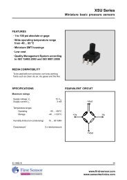
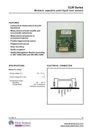
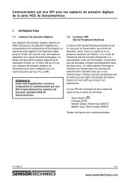
<strong>WBI</strong> <strong>Series</strong><br />
Mass flow sensors for gases<br />
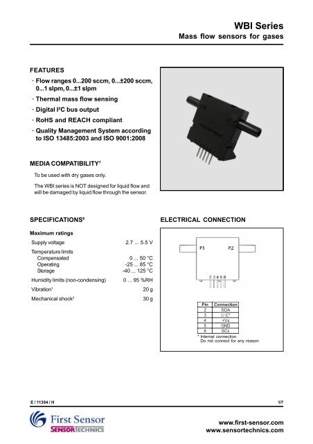
FEATURES<br />
· Flow ranges 0...200 sccm, 0...±200 sccm,<br />
0...1 slpm, 0...±1 slpm<br />
· Thermal mass flow sensing<br />
· Digital I²C bus output<br />
· RoHS and REACH compliant<br />
· Quality Management System according<br />
to ISO 13485:2003 and ISO 9001:2008<br />
MEDIA COMPATIBILITY 7<br />
To be used with dry gases only.<br />
The <strong>WBI</strong> series is NOT designed for liquid flow and<br />
will be damaged by liquid flow through the sensor.<br />
SPECIFICATIONS 6<br />
Maximum ratings<br />
Supply voltage<br />
2.7 ... 5.5 V<br />
Temperature limits<br />
Compensated 0 ... 50 °C<br />
Operating -25 ... 85 °C<br />
Storage -40 ... 125 °C<br />
Humidity limits (non-condensing) 0 ... 95 %RH<br />
Vibration 1<br />
20 g<br />
Mechanical shock 2<br />
30 g<br />
ELECTRICAL CONNECTION<br />
Pin<br />
Connection<br />
2 SDA<br />
3 I / C*<br />
4 +Vs<br />
5 GND<br />
6 SCL<br />
* Internal connection.<br />
Do not connect for any reason<br />
E / 11354 / H<br />
1/7<br />
www.first-sensor.com<br />
www.sensortechnics.com
<strong>WBI</strong> <strong>Series</strong><br />
Mass flow sensors for gases<br />
FLOW SENSOR CHARACTERISTICS 7<br />
(V S<br />
= 5 ±0.01 V, T A<br />
= 20 °C, P Abs<br />
= 101.325 kPa)<br />
Part<br />
no.<br />
<strong>WBI</strong>M200DU...<br />
<strong>WBI</strong>M200DB...<br />
<strong>WBI</strong>L001DU...<br />
<strong>WBI</strong>L001DB...<br />
Flow range<br />
0...200 sccm<br />
0...±200 sccm<br />
0...1 slpm<br />
0...±1 slpm<br />
Note:<br />
sccm denotes standard cubic centimeters per minute.<br />
slpm denotes standard liter per minute.<br />
Max. flow<br />
change<br />
5.0 slpm/sec<br />
Pressure drop<br />
0 .1 mbar @ 200 sccm<br />
0 .5 mbar @ 1 slpm<br />
Max. Common<br />
mode pressure<br />
25 psi<br />
PERFORMANCE CHARACTERISTICS 6<br />
(V S<br />
= 5 ±0.01 V, T A<br />
= 20 °C, P Abs<br />
= 101.325 kPa, output signal is ratiometric to V S<br />
, media = air)<br />
C haracteristics<br />
M in.<br />
T yp.<br />
Max.<br />
Unit<br />
3<br />
Accuracy<br />
±(2.0 % of reading +<br />
0.25 %FSO)<br />
4<br />
Total<br />
accuracy (0...50 °C)<br />
±(4.0 % of reading +<br />
0.25 %FSO)<br />
Repeatability (incl. hysteresis)<br />
0.25<br />
% of reading<br />
Offset<br />
long term stability (1 year)<br />
±0.05<br />
Noise<br />
level<br />
0. 1<br />
%FSS<br />
Current<br />
consumption (no load)<br />
10<br />
12<br />
mA<br />
Response<br />
time (t 90<br />
5<br />
8<br />
Warm-up<br />
time<br />
70<br />
ms<br />
Digital output<br />
C haracteristics<br />
M in.<br />
T yp.<br />
Max.<br />
S cale factor<br />
<strong>WBI</strong>M200..<br />
.<br />
150<br />
<strong>WBI</strong>L001...<br />
30<br />
Zero<br />
offset tolerance<br />
±0.25<br />
Full<br />
scale span tolerance<br />
±2.25<br />
Unit<br />
counts/sccm<br />
% FSS<br />
Note:<br />
The sensor’s performance is determined by intake flow conditions which depend on mounting and environmental<br />
effects. To ensure laminar flow through the sensor, it should be considered to insert a straight tube with a<br />
length 10 times the inner diameter of the pneumatic connector or a laminar flow element upstream of the<br />
sensor. Additionally, the <strong>WBI</strong> has to be mounted with both ports horizontally and pins downwards.<br />
E / 11354 / H<br />
2/7<br />
www.first-sensor.com<br />
www.sensortechnics.com
<strong>WBI</strong> <strong>Series</strong><br />
Mass flow sensors for gases<br />
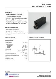
DIGITAL I²C BUS<br />
The <strong>WBI</strong> complies with the following protocol (Fig. 1):<br />
Bus idle (A): Both the series data line and the series<br />
clock line are HIGH.<br />
START condition (B): When SCL is HIGH, a change of SDA<br />
from HIGH to LOW represents a start condition that<br />
initiates data transfer. A start condition must present<br />
before any data transfer commands can be executed.<br />
STOP condition (C): When SCL is HIGH, a change of SDA<br />
from LOW to HIGH represents a stop condition that<br />
ceases data transfer. All the data transfer commands<br />
must be accomplished before a stop condition presents.<br />
DATA (D): After the start condition, the series data line<br />
must be kept steady when the series clock line is<br />
HIGH. The series data line can change during the<br />
period when the series clock line is LOW, and each<br />
data bit must correspond to a clock pulse.<br />
Each data transfer will begin with a start condition and<br />
cease after a stop condition. Every byte put on the<br />
series data line must be 8 bits long. The number of<br />
bytes that can be transmitted per transfer is<br />
unrestricted. Each byte has to be followed by an<br />
Acknowledge/not Acknowledge bit. The number of<br />
data bytes between a start condition and a stop<br />
condition will be decided by the bus master.<br />
Acknowledge bit: The master is initially in the master<br />
transmit mode by sending a start bit followed by the<br />
slave address that it wishes to communicate with,<br />
which is finally followed by a single bit representing<br />
whether it wishes to write(0) to or read(1) from the slave.<br />
If the slave exists on the bus then it will respond with<br />
acknowledge (ACK) bit (active low for acknowledged)<br />
for that address. The master must provide an extra<br />
SCL pulse for each ACK bit. The master then<br />
continues in either transmit or receive mode<br />
(according to the read/write bit it sent), and the slave<br />
continues in its complementary mode (receive or<br />
transmit, respectively).<br />
Slave address: The I²C-bus master-slave concept requires<br />
a unique address for each device on the bus. The <strong>WBI</strong><br />
has a reserved address (00h) for broadcasting and a<br />
second individual address preconfigured to 01h. The<br />
sensor will listen to both slave addresses. 00h can only<br />
be used for WRITE commands. By programming it is<br />
possible to reset the individual adress to any number<br />
between 1 and 127 (see Comands).<br />
After generating a START condition the master sends<br />
the address byte containing a 7 bit address followed<br />
by a data direction bit (R/W). A "0" indicates a<br />
transmission from master to slave (WRITE), a "1"<br />
indicates a data request (READ).<br />
DATA operation: The address and the data bytes are sent<br />
most significant bit first.<br />
If the master wishes to write into the slave then it<br />
repeatedly sends a byte with the slave sending an ACK<br />
bit. (In this situation, the master is in the master transmit<br />
mode and the slave is in the slave receive mode.)<br />
If the master wishes to read from the slave then it<br />
repeatedly receives a byte from the slave, the master<br />
sending an ACK bit after every byte but the last one. (In<br />
this situation, the master is in the master receive<br />
mode and the slave is in the slave transmit mode.)<br />
The master then ends transmission with a stop bit, or it<br />
may send another start bit if it wishes to retain control<br />
of the bus for another transfer (a "combined message").<br />
Note:<br />
The <strong>WBI</strong> sensor can hold SCL LOW after each data<br />
byte before ACK. The transaction cannot continue until<br />
SCL is HIGH again and therefore the master has to wait.<br />
(A) (B) (D) (D) (D) (C) (A)<br />
SCL<br />
SDA<br />
START<br />
condition<br />
Data<br />
valid<br />
Data<br />
allowed<br />
to change<br />
STOP<br />
condition<br />
Fig. 1:<br />
I²C bus protocol<br />
E / 11354 / H<br />
3/7<br />
www.first-sensor.com<br />
www.sensortechnics.com
<strong>WBI</strong> <strong>Series</strong><br />
Mass flow sensors for gases<br />
DIGITAL I²C BUS (cont.)<br />
Commands: The <strong>WBI</strong> series flow sensors use a<br />
communication mode based on the command<br />
interpretation mechanism. The data accesses are<br />
accomplished through various commands (Fig. 2):<br />
Read instant flow index<br />
0<br />
1<br />
S slave address R/W A 83h A S slave address R/W A data byte 1 A data byte 2 A data byte 3 A data byte 4 A P<br />
This command is used for enquiring the current instant flow index. The index consists of four 8-bit values,<br />
which are combined to give a 32-bit value as follows:<br />
( data byte 1×<br />
16777216) + ( data byte 2×<br />
65536) + ( data byte 3 × 256) ( data byte 4)<br />
Flow index =<br />
+<br />
The actual flow value can be calculated as the following:<br />
flow index<br />
Actual flow value =<br />
scale factor × 1000<br />
Negative numbers are represented by the two's complement.<br />
Example for <strong>WBI</strong>M200DBH5:<br />
Sensor output = FF FE 1D C0<br />
Flow index = -123456<br />
−123456<br />
Actual flow value =<br />
= − 0.823 sccm<br />
150 × 1000<br />
Read I²C address<br />
0<br />
1<br />
S slave address R/W A 85h A S slave address R/W A slave address 0 A P<br />
Write I²C address<br />
S<br />
0<br />
slave address R/W A 05h A<br />
new slave address<br />
0 A<br />
P<br />
Auto zero<br />
S<br />
0<br />
slave address R/W A 1Ch A 00h A P<br />
generated by master<br />
generated by slave<br />
S = START condition<br />
A = Acknowledge<br />
P = STOP condition<br />
Fig. 2:<br />
<strong>WBI</strong> commands<br />
E / 11354 / H<br />
4/7<br />
www.first-sensor.com<br />
www.sensortechnics.com
<strong>WBI</strong> <strong>Series</strong><br />
Mass flow sensors for gases<br />
DIGITAL I²C BUS (cont.)<br />
I²C Interface Parameters<br />
Parameter<br />
S ymbol<br />
M in.<br />
T yp.<br />
Max.<br />
Unit<br />
Input<br />
high level<br />
90<br />
100<br />
Input<br />
low level<br />
0 10<br />
% of Vs<br />
Output<br />
low level<br />
10<br />
Pull-up<br />
resistor<br />
10<br />
kΩ<br />
Load<br />
capacitance @ SDA<br />
C SDA<br />
400<br />
Input<br />
capacitance @ SDA/SCL<br />
C I2C_IN<br />
10<br />
pF<br />
SCL clock frequency<br />
F SCL<br />
100<br />
kHz<br />
Bus<br />
free time between STOP and START condition tBU<br />
F<br />
4. 7<br />
Hold<br />
time (repeated) START condition, to<br />
first clock pulse<br />
tH D.STA<br />
4. 7<br />
LOW period of SCL<br />
tLO<br />
W<br />
4. 7<br />
HIGH period of SCL<br />
tH IGH<br />
4. 0<br />
Setup<br />
time repeated START condition<br />
tSU.ST<br />
A<br />
4. 7<br />
Data<br />
hold time<br />
tH D.DAT<br />
0<br />
µs<br />
Data<br />
setup time<br />
tSU.DA<br />
T<br />
0.25<br />
Rise<br />
time of both SDA and SCL<br />
t R<br />
1<br />
Fall<br />
time of both SDA and SCL<br />
t F<br />
0. 3<br />
Setup<br />
time for STOP condition<br />
tSU.ST<br />
O<br />
4<br />
tSU;DAT tHD;DAT tSU;STA tHD;STA tR tF<br />
SCL<br />
SDA<br />
tHIGH tLOW tSU;STO tBUF tHD;STA<br />
SCL<br />
SDA<br />
Fig. 3:<br />
Timing characteristics<br />
E / 11354 / H<br />
5/7<br />
www.first-sensor.com<br />
www.sensortechnics.com
<strong>WBI</strong> <strong>Series</strong><br />
Mass flow sensors for gases<br />
OUTLINE DRAWING<br />
Note:<br />
Positive flow direction is<br />
defined as proceeding<br />
from P1 to P2 and results<br />
in positive output.<br />
third angle projection<br />
dimensions in mm<br />
E / 11354 / H<br />
6/7<br />
www.first-sensor.com<br />
www.sensortechnics.com
<strong>WBI</strong> <strong>Series</strong><br />
Mass flow sensors for gases<br />
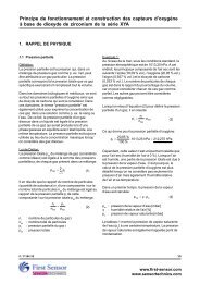
GAS CORRECTION FACTORS 9<br />
Gas<br />
type<br />
Air<br />
1. 0<br />
Oxygen (O 2 1. 0<br />
Nitrogen (N 2 1. 0<br />
Argon (Ar)<br />
1.18<br />
Hydrogen (H 2 *<br />
Carbon dioxide (CO 2 0.67<br />
Gas correction factor<br />
* For Hydrogen applications, the actual H 2<br />
calibration is performed whenever possible.<br />
Specification notes:<br />
1. Sweep 20 to 2000 Hz, 8 min, 4 cycles per axis, MIL-STD-883, Method 2007.<br />
2. 5 shocks, 3 axes, MIL-STD-883E, Method 2002.4.<br />
3. Accuracy is the combined error from offset and span calibration, linearity, hysteresis and repeatability.<br />
4. Total accuracy is the combined error from offset and span calibration, linearity, hysteresis, repeatability and temperature effects.<br />
5. Full Scale Span (FSS) is the algebraic difference between the output signal for the highest and lowest specified flow.<br />
6. Specification is preliminary. Data sheet is based on Pre-<strong>Series</strong> sample verification.<br />
7. A 5 µm filter is recommended to protect the sensing element from dust particles which may be present in some applications.<br />
8. Warm-up time is the time from power on to the first stable reading.<br />
9. To obtain the real flow rates in a specific gas, multiply the readings from the sensor by the gas correction factor in the table. The<br />
factors are approximate and should be used as guidelines only. Sensor performance strongly depends on gas dynamics and has<br />
to be evaluated in the respective application.<br />
ORDERING INFORMATION<br />
Options<br />
Example:<br />
<strong>Series</strong><br />
<strong>WBI</strong><br />
M200<br />
Flow range<br />
L001<br />
200<br />
sccm<br />
D*<br />
Gas<br />
Flow direction<br />
Grade<br />
Dry air<br />
B Bidirectional<br />
H High<br />
5 5 V<br />
1 slpm<br />
U Unidirectiona l<br />
* other calibration<br />
gases on request<br />
<strong>WBI</strong><br />
M200<br />
D U H 5<br />
Calibratio n<br />
( V =2.7...5.5 V)<br />
S<br />
First Sensor reserves the right to make changes to any products herein.<br />
First Sensor does not assume any liability arising out of the application<br />
or use of any product or circuit described herein, neither does it convey<br />
any license under its patent rights nor the rights of others.<br />
E / 11354 / H<br />
7/7<br />
www.first-sensor.com<br />
www.sensortechnics.com