Universal Turn Signal Kit - Painless Wiring
Universal Turn Signal Kit - Painless Wiring
Universal Turn Signal Kit - Painless Wiring
You also want an ePaper? Increase the reach of your titles
YUMPU automatically turns print PDFs into web optimized ePapers that Google loves.
2501 Ludelle Street<br />
Fort Worth, Texas 76105<br />
817-244-6212 Phone • 817-244-4024 Fax<br />
888-350-6588 Sales • 800-423-9696 Tech<br />
E-mail: painless@painlessperformance.com<br />
Web: www.painlessperformance.com<br />
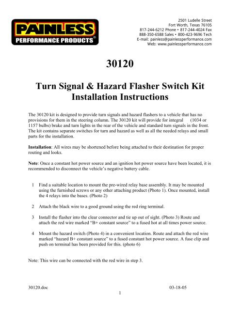
30120<br />
<strong>Turn</strong> <strong>Signal</strong> & Hazard Flasher Switch <strong>Kit</strong><br />
Installation Instructions<br />
The 30120 kit is designed to provide turn signals and hazard flashers to a vehicle that has no<br />
provisions for them in the steering column. The 30120 kit will provide for integral (1034 or<br />
1157 bulbs) brake and turn lights in the rear of the vehicle and standard turn signals in the front.<br />
The kit contains separate switches for turn and hazard as well as all the needed relays and small<br />
parts for the installation.<br />
Installation: All wires may be shortened before being attached to their destination for proper<br />
routing and looks.<br />
Note: Once a constant hot power source and an ignition hot power source have been located, it is<br />
recommended to disconnect the vehicle’s negative battery cable.<br />
1 Find a suitable location to mount the pre-wired relay base assembly. It may be mounted<br />
using the furnished screws or any other attaching product (Photo 1). Once mounted, install<br />
the 4 relays into the bases. (Photo 2)<br />
2 Attach the black wire to a good ground using the red ring terminal.<br />
3 Install the flasher into the clear connector and tie up out of sight. (Photo 3) Route and<br />
attach the red wire marked “B+ constant source” to a fused hot at all times power source.<br />
4 Mount the hazard switch (Photo 4) in a convenient location. Route and attach the red wire<br />
marked “hazard B+ constant source” to a fused constant hot power source. A fuse clip and<br />
push on terminal has been provided for this. (photo 6)<br />
Note: This wire can be connected with the red wire in step 3.<br />
30120.doc 03-18-05<br />
1
5 Take the light blue wire with a white stripe and hazard #1 wire and crimp both into one of<br />
the blue ring terminals. Take the blue wire with a white stripe and hazard #2 wire and<br />
crimp both into the other blue ring terminal. (Photo 5) Once crimped, each ring terminal<br />
may be attached to the turn switch. At this point it makes no difference which blue ring<br />
terminal goes to which terminal on the switch. Mount the switch.<br />
6 Route and attach the remaining red wire from the turn switch marked “turn B+ switched” to<br />
a fused ignition switched power source. This wire may also be attached to a fuse using the<br />
adapter terminals provided.<br />
7 Route and attach the white wire marked “brake switch input” to the cold side of the brake<br />
switch. The cold side will have power only when the brake pedal is depressed. This wire<br />
will replace the wire on the cold side, if so equipped.<br />
8 Route the long blue wire marked “right front turn signal” and light blue wire marked “left<br />
front turn signal” to the front of the vehicle and attach. If dash indicators are to be installed,<br />
they should be spliced into these wires.<br />
9 Route the remaining yellow wire marked “left rear turn signal” and the green wire marked<br />
“right rear turn signal” to the rear of the vehicle and attach. The yellow and green wires<br />
will serve as the brake light and turn power wires to each light which will replace any<br />
existing brake light wires.<br />
10 Reconnect the vehicle’s negative battery cable.<br />
11 With the ignition switch on, flip the turn toggle switch to the left and the left turn indicator<br />
should flash. If the right flashes simply rotate the switch 180 degrees.<br />
12 Test to make sure that the brake and turn lights operate correctly.<br />
Also when the hazard switch is turned on all lights should flash.<br />
2
Photo #1 Photo #2<br />
Photo #3 Photo #4<br />
Photo #5 Photo #6<br />
3
<strong>Painless</strong> Performance Limited Warranty<br />
and Return Policy<br />
Chassis harnesses and fuel injection harnesses are covered under a lifetime warranty. All other<br />
products manufactured and/or sold by <strong>Painless</strong> Performance are warranted to the original<br />
purchaser to be free from defects in material and workmanship under normal use. <strong>Painless</strong><br />
Performance will repair or replace defective products without charge during the first 12 months<br />
from the purchase date. No products will be considered for warranty without a copy of the<br />
purchase receipt showing the sellers name, address and date of purchase. You must return the<br />
product to the dealer you purchased it from to initiate warranty procedures.<br />
Copyright © 2007 by Perfect Performance Products, LLC<br />
4


