Semiconductor optical amplifier pattern effect suppression using ...
Semiconductor optical amplifier pattern effect suppression using ...
Semiconductor optical amplifier pattern effect suppression using ...

You also want an ePaper? Increase the reach of your titles
YUMPU automatically turns print PDFs into web optimized ePapers that Google loves.
<strong>Semiconductor</strong> <strong>optical</strong> <strong>amplifier</strong> <strong>pattern</strong><br />
<strong>effect</strong> <strong>suppression</strong> <strong>using</strong> Lyot filter<br />
K.E. Zoiros, C. O’Riordan and M.J. Connelly<br />
The feasibility of employing a Lyot filter to compensate for the <strong>pattern</strong><br />
<strong>effect</strong> in a semiconductor <strong>optical</strong> <strong>amplifier</strong> (SOA) is experimentally<br />
demonstrated. The operation mechanism relies on the control of its<br />
comb-like transfer function by proper adjustment of the wavelength<br />
spacing and detuning to suppress the spectral components broadened<br />
owing to SOA gain saturation. The scheme is experimentally demonstrated<br />
on amplified 10 Gbit/s return to zero data.<br />
Introduction: <strong>Semiconductor</strong> <strong>optical</strong> <strong>amplifier</strong>s (SOAs) have become a<br />
key technology for the development of lightwave communications and<br />
networks enabled by their ultra-wide bandwidth, low power consumption,<br />
compactness and ability for integration [1]. Nevertheless, in direct<br />
signal amplification applications the combination of the power and the<br />
duration of the input signal pulses can be such that the SOA is driven<br />
into intense saturation and cannot fully recover its gain until its next<br />
excitation. If a random data stream is launched into the SOA, the<br />
resulting gain saturation and finite recovery time results in an amplified<br />
output that is not uniform, leading to degradation in system<br />
performance [2]. One solution that has been proposed to resolve this<br />
problem relies on the fact that the strong gain saturation also induces<br />
self-phase modulation (SPM), resulting in broadening of the pulse<br />
spectrum [3]. If the unwanted frequency-shifted components are appropriately<br />
suppressed then the <strong>pattern</strong>-dependent distortion on the amplified<br />
data stream can be cancelled as reported in [4–6]. In this Letter we<br />
propose to implement this technique <strong>using</strong> a Lyot filter [7] to greatly<br />
reduce the <strong>pattern</strong> <strong>effect</strong> on a 10 Gbit/s return-to-zero (RZ) data<br />
pulse stream amplified by an SOA. Such Lyot filters have previously<br />
only been used for signal processing [8] and in multi-wavelength<br />
lasers [9]. Owing to the Lyot filter’s low cost, relatively simple<br />
construction, periodic transfer function, good peak-to-notch contrast<br />
ratio, reasonable insertion loss, operational stability and flexible<br />
tunability it can be an efficient alternative option to existing schemes<br />
[4–6].<br />
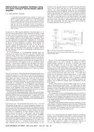
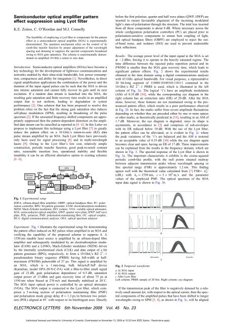
BPG<br />
CLK data<br />
EDFA<br />
PC<br />
PC<br />
ISO<br />
VOA<br />
CW laser Laser<br />
source<br />
OBPF<br />
EAM<br />
MZM<br />
Source<br />
PMF<br />
OSA<br />
OC<br />
ISO<br />
POL<br />
POL<br />
OBPF<br />
SOA<br />
45 o 45 o<br />
DCA<br />
Lyot filter<br />
Fig. 1 Experimental setup<br />
HWP<br />
QWP<br />
EDFA: erbium-doped fibre <strong>amplifier</strong>, OBPF: <strong>optical</strong> bandpass filter, PC: polarisation<br />
controller, BPG: bit <strong>pattern</strong> generator, EAM: electroabsorption modulator,<br />
MZM: Mach-Zehnder modulator, ISO: isolator, VOA: variable <strong>optical</strong> attenuator,<br />
SOA: semiconductor <strong>optical</strong> <strong>amplifier</strong>, QWP: quarter wave plate, HWP: half wave<br />
plate, POL: polariser, PMF: polarisation-maintaining fibre, OC: <strong>optical</strong> coupler,<br />
DCA: digital communications analyser, OSA: <strong>optical</strong> spectrum analyser<br />
Experiment: Fig. 1 illustrates the experimental setup for demonstrating<br />
the <strong>pattern</strong> <strong>effect</strong> induced on RZ pulses when amplified in an SOA and<br />
verifying the capability of the proposed scheme to suppress it. A<br />
1550 nm tunable laser source is amplified by an erbium-doped fibre<br />
<strong>amplifier</strong> and subsequently modulated by an electroabsorption modulator<br />
(EAM) and a LiNbO 3 Mach-Zehnder modulator (MZM) driven<br />
by the internally synchronised clock (CLK) and data output of a bit<br />
<strong>pattern</strong> generator (BPG), respectively, to form a 10 Gbit/s RZ2 7 –1<br />
pseudorandom binary sequence (PRBS) having full-width at halfmaximum<br />
(FWHM) pulsewidth of 27 ps. This signal is amplified by<br />
an SOA, which is a 1 mm-long, bulk InGaAsP/InP device<br />
(Kamelian, model OPA-20-N-C-FA) with a fibre-to-fibre small signal<br />
gain of 23 dB, gain polarisation dependence of 0.5 dB, saturation<br />
output power of 13 dBm and gain recovery time of about 75 ps at<br />
1550 nm when biased at 270 mA and thermally stabilised at 208C.<br />
The SOA input <strong>optical</strong> power is controlled by an <strong>optical</strong> attenuator<br />
(VOA). The SOA output is connected to the Lyot filter, which comprises<br />
a 5 m-long section of polarisation maintaining fibre (PMF)<br />
and polarisation mode group delay B ¼ 1.3 ps/m between two polarisers<br />
(POL) aligned at 458 with respect to its birefringent axes. Directly<br />
PC<br />
before the first polariser, quarter and half wave plates (QWP, HWP) are<br />
inserted to ensure favourable alignment of the incoming modulated<br />
light’s state-of-polarisation through the structure. The total loss inserted<br />
from all these components is about 8 dB. Where necessary across the<br />
whole configuration polarisation controllers (PC) are placed prior to<br />
polarisation-sensitive components to ensure best coupling of light,<br />
and <strong>optical</strong> bandpass filters (OBPF) are employed to reject the outof-band<br />
noise, and isolators (ISO) are used to prevent undesirable<br />
back reflections.<br />
Results: The average power level of the input signal to the SOA is set<br />
at 22 dBm, forcing it to operate in the heavily saturated regime. The<br />
time difference between the injected pulse repetition period and its<br />
FWHM is smaller than the SOA gain recovery time, which leads to<br />
significant <strong>pattern</strong> <strong>effect</strong>s. Fig. 2 shows the experimental results<br />
obtained in the time domain <strong>using</strong> a digital communications analyser<br />
with 65 GHz <strong>optical</strong> bandwidth. For visual purposes, a representative<br />
20 bit-long segment of 11000110100101110111 contained in the<br />
10 Gbit/s RZ 2 7 –1 PRBS is used, which is illustrated in the left<br />
column of Fig. 2a. The logical ‘1’s have an amplitude modulation<br />
(AM) of 0.35 dB [10], while the corresponding eye diagram in the<br />
right column has an extinction ratio (ER) of 20 dB. After the SOA<br />
alone, however, these features are not maintained owing to the pronounced<br />
<strong>pattern</strong> <strong>effect</strong>, which results in a poor performance observed<br />
in Fig. 2b. In fact, the marks suffer from severe amplitude fluctuations<br />
depending on whether they are preceded either by one or more spaces<br />
or other marks, as theoretically predicted in [10], resulting in an AM of<br />
1.7 dB. Moreover, the eye diagram is degraded, since its shape is<br />
asymmetric, in accordance to [3] and comprises of sub-envelopes<br />
with its ER reduced below 10 dB. With the use of the Lyot filter,<br />
the <strong>pattern</strong> <strong>effect</strong> can be alleviated, as is evident in Fig. 2c where<br />
the peak variations of the ‘1’s are balanced and the AM is restored<br />
to an acceptable value of 0.35 dB [10] while the eye diagram again<br />
becomes clear and open, having an ER of 17 dB. These improvements<br />
can be explained from the results in the frequency domain, which are<br />
shown in Fig. 3. The spectral response of the Lyot filter is shown in<br />
Fig. 3a. The important characteristic it exhibits is the cosine-squared<br />
periodic comb-like profile, with the null points situated midway<br />
between adjacent transmission peaks whose wavelength spacing or<br />
free spectral range (FSR) is approximately 1.2 nm. This finding<br />
agrees well with the theoretical value calculated from [7] FSR¼ l o 2 /<br />
(cBL) with l o ¼ 1550 nm, c ¼ 3 10 8 m/s and the parameter<br />
values of the employed PMF. The <strong>optical</strong> spectrum of the SOA<br />
input data signal is shown in Fig. 3b.<br />
Fig. 2 Temporal waveforms<br />
a<br />
b<br />
200 ps/div. 10 ps/div.<br />
a At SOA input<br />
b At SOA output<br />
c After Lyot filter<br />
Left column: PRBS sample of 20 bits. Right column: eye diagram<br />
c<br />
If the transmission peak of the filter is negatively detuned by a relatively<br />
small amount Dl, with respect to the <strong>optical</strong> carrier, then the spectral<br />
components of the amplified pulses that have been shifted to longer<br />
wavelengths owing to SPM [3, 4], as shown in Fig. 3c, will be aligned<br />
ELECTRONICS LETTERS 5th November 2009 Vol. 45 No. 23<br />
Authorized licensed use limited to: University of Limerick. Downloaded on November 13, 2009 at 10:32 from IEEE Xplore. Restrictions apply.
with the sharp notches of the Lyot filter response. The relative attenuation<br />
imposed by these notches is approximately 24 dB across the<br />
entire tuning range, thereby being attenuated in direct analogy to<br />
the degree of their shift. This can be done practically by choosing first<br />
the appropriate PMF length to adjust the FSR through a trial and error<br />
procedure that relies on the AM extent and the efficiency with which<br />
it must be reduced, and then rotating the wave plates to introduce the<br />
additional phase shift, Dw, in order to vary Dl up to 50% of the FSR<br />
according to Dl ¼ (Dw/2p) FSR [7]. In this manner, the Lyot filter<br />
can suppress the red-shifted spectral components, as shown in Fig. 3d,<br />
and consequently the distortion in the profile of the amplified signal is<br />
removed, while the input power dynamic range is increased by an<br />
amount estimated according to the SOA characterisation data to be<br />
5 dB. On the other hand, the price paid for the significant performance<br />
improvements achieved by its use is that the data sequence receives a<br />
peak amplification of about 2.5 dB less than after the SOA only. This<br />
happens because due to the filtering action a portion of information contained<br />
in the suppressed red-shifted spectral components is inevitably<br />
lost. Furthermore, the temperature dependence of the birefringence of<br />
the PMF causes a drift of the polarisation vector and subsequently a<br />
slow variation of the <strong>pattern</strong> amplitude so that during the experiment<br />
it was possible to achieve error-free operation for a very short time.<br />
However, this is not a fundamental problem but rather a technical difficulty<br />
that can be overcome with the commercially available technology,<br />
such as specialised PM photonic crystal fibres [11], which can enhance<br />
the stability of the scheme by making it less sensitive to changes in the<br />
environmental conditions. In comparison, there are other comb filter<br />
implementations with delay interferometers which are more robust to<br />
environmental perturbations, such as the birefringent fibre loop (BFL)<br />
[12] and the <strong>optical</strong> delay interferometer (ODI) [10]. The latter is also<br />
more compact and can be co-packaged with the SOA in a single<br />
module, which is more difficult to be done with the Lyot filter owing<br />
to its large physical size.<br />
transmission, dB<br />
power, dBm<br />
0<br />
0<br />
–5<br />
–10<br />
–10<br />
–20<br />
–15<br />
–20<br />
–30<br />
–25<br />
–40<br />
–30<br />
–50<br />
–35<br />
–60<br />
–40<br />
–45<br />
–70<br />
1547.0<br />
1550.0<br />
1553.0 1548.5 1550.0 1551.5<br />
λ, nm<br />
λ, nm<br />
a<br />
b<br />
0<br />
0<br />
–10<br />
–10<br />
–20<br />
–20<br />
–30<br />
–30<br />
–40<br />
–40<br />
–50<br />
–50<br />
–60<br />
–60<br />
–70<br />
1548.5 1550.0 1551.5 1548.5 1550.0 1551.5<br />
λ, nm<br />
λ, nm<br />
c<br />
d<br />
Fig. 3 Measured <strong>optical</strong> spectra<br />
a Lyot filter response<br />
b SOA input<br />
c SOA output<br />
b After Lyot filter<br />
power, dBm<br />
power, dBm<br />
Conclusion: The capability of a Lyot birefringent comb filter to mitigate<br />
the <strong>pattern</strong>-dependent pulse distortion in a SOA employed in its classical<br />
amplification role has been experimentally demonstrated. The confirmed<br />
performance improvement suggests that this scheme can constitute a<br />
promising technological solution for combating the deleterious consequences<br />
of this <strong>effect</strong>.<br />
# The Institution of Engineering and Technology 2009<br />
15 June 2009<br />
doi: 10.1049/el.2009.1701<br />
K.E. Zoiros, C. O’Riordan and M.J. Connelly (Optical Communications<br />
Research Group, Department of Electronic and Computer Engineering,<br />
University of Limerick, Limerick, Ireland)<br />
E-mail: kzoiros@ee.duth.gr<br />
K.E. Zoiros: On leave from Department of Electrical and Computer<br />
Engineering, Democritus University of Thrace, Xanthi, Greece<br />
References<br />
1 Connelly, M.J.: ‘<strong>Semiconductor</strong> <strong>optical</strong> <strong>amplifier</strong>s’ (Kluwer Academic<br />
Press, Boston, MA, 2002)<br />
2 Manning, R.J., Ellis, A.D., Poustie, A.J., and Blow, K.J.:<br />
‘<strong>Semiconductor</strong> laser <strong>amplifier</strong>s for ultrafast all-<strong>optical</strong> signal<br />
processing’, J. Opt. Soc. Am. B, 1997, 14, (11), pp. 3204–3216<br />
3 Agrawal, G.P., and Olsson, N.A.: ‘Self-phase modulation and spectral<br />
broadening of <strong>optical</strong> pulses in semiconductor laser <strong>amplifier</strong>s’,<br />
J. Quantum Electron., 1989, 25, (11), pp. 2297–2306<br />
4 Dong, J., Zhang, X., Wang, F., Hong, W., and Huang, D.:<br />
‘Experimental study of SOA-based NRZ-to-PRZ conversion and<br />
distortion elimination of amplified NRZ signal <strong>using</strong> spectral<br />
filtering’, Opt. Commun., 2008, 281, (22), pp. 5618–5624<br />
5 Yu, J., and Jeppesen, P.: ‘Increasing input power dynamic range of SOA<br />
by shifting the transparent wavelength of tunable <strong>optical</strong> filter’,<br />
J. Lightwave Technol., 2001, 19, (9), pp. 1316–1325<br />
6 Inoue, K.: ‘Optical filtering technique to suppress waveform distortion<br />
induced in a gain-saturated semiconductor <strong>optical</strong> <strong>amplifier</strong>’, Electron.<br />
Lett., 1997, 33, (10), pp. 885–886<br />
7 Wang, M., Fu, S., Shum, P., Ngo, N.Q., Wu, J., and Lin, J.: ‘A tunable<br />
Lyot birefringent filter with variable channel spacing and wavelength<br />
<strong>using</strong> nonlinear polarization rotation in an SOA’, IEEE Photonics<br />
Technol. Lett., 2008, 20, (18), pp. 1527–1529<br />
8 Kumavor, P.D., Donkor, E., and Wang, B.C.: ‘All-<strong>optical</strong> Lyot-filterassisted<br />
flip-flop operation <strong>using</strong> a semiconductor <strong>optical</strong> <strong>amplifier</strong>’,<br />
IEEE J. Sel. Top. Quantum Electron., 2006, 12, (4), pp. 697–701<br />
9 Pleros, N., Houbavlis, T., Theophilopoulos, G., Vlachos, K., Bintjas, C.,<br />
and Avramopoulos, H.: ‘SOA-based multi-wavelength laser sources’,<br />
Fiber Integr. Opt., 2004, 23, (4), pp. 263–274<br />
10 Zoiros, K.E., Siarkos, T., and Koukourlis, C.S.: ‘Theoretical analysis of<br />
<strong>pattern</strong> <strong>effect</strong> <strong>suppression</strong> in semiconductor <strong>optical</strong> <strong>amplifier</strong> utilizing<br />
<strong>optical</strong> delay interferometer’, Opt. Commun., 2008, 281, (14),<br />
pp. 3648–3657<br />
11 Kim, D.H., and Kang, J.U.: ‘Analysis of temperature-dependent<br />
birefringence of a polarization-maintaining photonic crystal fiber’,<br />
Opt. Eng., 2007, 46, (7), p. 075003<br />
12 Chow, C.W., Wong, C.S., and Tsang, H.K.: ‘Reduction of amplitude<br />
transients and BER of direct modulation laser <strong>using</strong> birefringent fiber<br />
loop’, IEEE Photonics Technol. Lett., 2005, 17, (3), pp. 693–695<br />
ELECTRONICS LETTERS 5th November 2009 Vol. 45 No. 23<br />
Authorized licensed use limited to: University of Limerick. Downloaded on November 13, 2009 at 10:32 from IEEE Xplore. Restrictions apply.