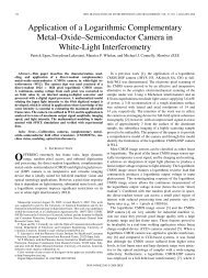
Optical phase conjugation technique using four-wave mixing in ...
Optical phase conjugation technique using four-wave mixing in ...
Optical phase conjugation technique using four-wave mixing in ...

Create successful ePaper yourself
Turn your PDF publications into a flip-book with our unique Google optimized e-Paper software.
<strong>Optical</strong> <strong>phase</strong> <strong>conjugation</strong> <strong>technique</strong> <strong>us<strong>in</strong>g</strong><br />
<strong>four</strong>-<strong>wave</strong> <strong>mix<strong>in</strong>g</strong> <strong>in</strong> semiconductor optical<br />
amplifier<br />
C.L. Janer and M.J. Connelly<br />
A semiconductor-optical-amplifier-based <strong>technique</strong> to generate the<br />
conjugate of an optical signal is presented. The orig<strong>in</strong>al probe signal<br />
and its conjugate appear at opposite ends of the semiconductor<br />
optical amplifier, improv<strong>in</strong>g, therefore, exist<strong>in</strong>g <strong>technique</strong>s. The basic<br />
concept was proposed many years ago but, to the best of our knowledge,<br />
has never been experimentally verified. An explanation is<br />
given as to why this was not possible, what modifications render the<br />
idea practical are expla<strong>in</strong>ed and experimental results that prove its feasibility<br />
are shown.<br />
Introduction: In 1988 Agrawal published a theoretical paper [1] on<br />
<strong>four</strong>-<strong>wave</strong> <strong>mix<strong>in</strong>g</strong> that has been widely referenced. In analogy to what<br />
is usually done with nonl<strong>in</strong>ear crystals or <strong>in</strong> resonant two-level media<br />
[2], he proposed a bidirectional pump<strong>in</strong>g scheme <strong>in</strong> a semiconductor<br />
optical amplifier (SOA) to achieve optical <strong>phase</strong> <strong>conjugation</strong>. There<br />
are many applications of optical <strong>phase</strong> <strong>conjugation</strong> [3], <strong>in</strong> particular<br />
chromatic dispersion compensation [4]. Agrawal studied and modelled<br />
the physics of carrier population oscillations, which underlies the<br />
<strong>four</strong>-<strong>wave</strong> <strong>mix<strong>in</strong>g</strong> phenomena that take place <strong>in</strong> the device [5].<br />
Agrawal predicted the characteristics of the probe and conjugate<br />
optical signals and particularly their appearance at opposite ends of<br />
the SOA. However, to the best of our knowledge, such behaviour has<br />
never been reported.<br />
In [6] the generation of a co-propagat<strong>in</strong>g conjugate signal was<br />
attributed to the residual facet reflectivity of the SOA. We believe this<br />
is not the reason. In fact, s<strong>in</strong>ce [6] was published the effective facet<br />
reflectivities of SOAs have been considerably reduced (by around two<br />
orders of magnitude) and still no such behaviour has yet been reported.<br />
What is systematically measured are the probe and conjugate <strong>wave</strong>s at<br />
both ends of the SOA. These signals can only be separated by optical<br />
filter<strong>in</strong>g [7], which makes it difficult to take advantage of the nearlydegenerate<br />
regime (small pump-probe frequency detun<strong>in</strong>g). <strong>Optical</strong><br />
filter<strong>in</strong>g makes the experimental setup very complex if the frequency<br />
detun<strong>in</strong>g between the pump and conjugate <strong>wave</strong>s is below the terahertz<br />
range [7].<br />
Physical <strong>in</strong>terpretation: The beat<strong>in</strong>g between the pump and probe <strong>wave</strong>s<br />
is taken <strong>in</strong>to account <strong>in</strong> [1] as this process is the driv<strong>in</strong>g mechanism of<br />
population oscillations. However, the fact that the counter-propagat<strong>in</strong>g<br />
pump signals can create a stand<strong>in</strong>g <strong>wave</strong> <strong>in</strong>side the cavity was not<br />
considered. Such a stand<strong>in</strong>g <strong>wave</strong> results <strong>in</strong> a periodic longitud<strong>in</strong>al<br />
spatial carrier distribution that leads to an associated periodic refractive<br />
<strong>in</strong>dex profile (i.e. a Bragg grat<strong>in</strong>g). The Bragg grat<strong>in</strong>g <strong>wave</strong>length peak<br />
is automatically tuned (that is to say, the reflectivity takes its highest<br />
value) to the pump<strong>in</strong>g <strong>wave</strong>length. The reflection bandwidth strongly<br />
depends on the amplitude of the refractive <strong>in</strong>dex modulation, cavity<br />
length and longitud<strong>in</strong>al optical power distribution and can be very large<br />
for long cavities and high refractive <strong>in</strong>dex changes [8].<br />
We th<strong>in</strong>k that this Bragg grat<strong>in</strong>g partially reflects backwards the probe<br />
and <strong>phase</strong> conjugated <strong>wave</strong>s, which expla<strong>in</strong>s why their counter propagation<br />
<strong>in</strong>side the SOA has never been reported before. A simple way to avoid<br />
this complication is to <strong>in</strong>ject orthogonally counter-propagat<strong>in</strong>g pump<br />
signals (at the same <strong>wave</strong>length). Such pump <strong>wave</strong>s will not <strong>in</strong>terfere to<br />
create a Bragg grat<strong>in</strong>g <strong>in</strong> the SOA.<br />
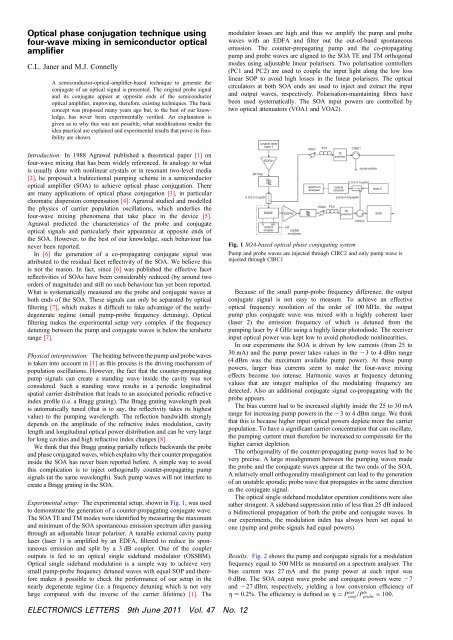
Experimental setup: The experimental setup, shown <strong>in</strong> Fig. 1, was used<br />
to demonstrate the generation of a counter-propagat<strong>in</strong>g conjugate <strong>wave</strong>.<br />
The SOA TE and TM modes were identified by measur<strong>in</strong>g the maximum<br />
and m<strong>in</strong>imum of the SOA spontaneous emission spectrum after pass<strong>in</strong>g<br />
through an adjustable l<strong>in</strong>ear polariser. A tunable external cavity pump<br />
laser (laser 1) is amplified by an EDFA, filtered to reduce its spontaneous<br />
emission and split by a 3 dB coupler. One of the coupler<br />
outputs is fed to an optical s<strong>in</strong>gle sideband modulator (OSSBM).<br />
<strong>Optical</strong> s<strong>in</strong>gle sideband modulation is a simple way to achieve very<br />
small pump-probe frequency detuned <strong>wave</strong>s with equal SOP and therefore<br />
makes it possible to check the performance of our setup <strong>in</strong> the<br />
nearly degenerate regime (i.e. a frequency detun<strong>in</strong>g which is not very<br />
large compared with the <strong>in</strong>verse of the carrier lifetime) [1]. The<br />
modulator losses are high and thus we amplify the pump and probe<br />
<strong>wave</strong>s with an EDFA and filter out the out-of-band spontaneous<br />
emission. The counter-propagat<strong>in</strong>g pump and the co-propagat<strong>in</strong>g<br />
pump and probe <strong>wave</strong>s are aligned to the SOA TE and TM orthogonal<br />
modes <strong>us<strong>in</strong>g</strong> adjustable l<strong>in</strong>ear polarisers. Two polarisation controllers<br />
(PC1 and PC2) are used to couple the <strong>in</strong>put light along the low loss<br />
l<strong>in</strong>ear SOP to avoid high losses <strong>in</strong> the l<strong>in</strong>ear polarisers. The optical<br />
circulators at both SOA ends are used to <strong>in</strong>ject and extract the <strong>in</strong>put<br />
and output <strong>wave</strong>s, respectively. Polarisation-ma<strong>in</strong>ta<strong>in</strong><strong>in</strong>g fibres have<br />
been used systematically. The SOA <strong>in</strong>put powers are controlled by<br />
two optical attenuators (VOA1 and VOA2).<br />
BP filter<br />
0.5:0.5 coupler<br />
tunable laser<br />
laser 1<br />
EDFA1<br />
DDMZ<br />
0 90°<br />
hybrid<br />
coupler<br />
EDFA2<br />
RF<br />
OSSB<br />
modulator<br />
VOA1 PC1 CIRC1<br />
spectrum<br />
analyser<br />
VOA2<br />
PC2<br />
TE<br />
polariser<br />
optical<br />
receiver<br />
pump+conjugate<br />
TE<br />
polariser<br />
Fig. 1 SOA-based optical <strong>phase</strong> conjugat<strong>in</strong>g system<br />
pump+probe<br />
0.5:0.5 coupler<br />
CIRC2<br />
laser 2<br />
Pump and probe <strong>wave</strong>s are <strong>in</strong>jected through CIRC2 and only pump <strong>wave</strong> is<br />
<strong>in</strong>jected through CIRC1<br />
Because of the small pump-probe frequency difference, the output<br />
conjugate signal is not easy to measure. To achieve an effective<br />
optical frequency resolution of the order of 100 MHz, the output<br />
pump plus conjugate <strong>wave</strong> was mixed with a highly coherent laser<br />
(laser 2) the emission frequency of which is detuned from the<br />
pump<strong>in</strong>g laser by 4 GHz <strong>us<strong>in</strong>g</strong> a highly l<strong>in</strong>ear photodiode. The receiver<br />
<strong>in</strong>put optical power was kept low to avoid photodiode nonl<strong>in</strong>earities.<br />
In our experiments the SOA is driven by low currents (from 25 to<br />
30 mA) and the pump power takes values <strong>in</strong> the 23 to 4 dBm range<br />
(4 dBm was the maximum available pump power). At these pump<br />
powers, larger bias currents seem to make the <strong>four</strong>-<strong>wave</strong> <strong>mix<strong>in</strong>g</strong><br />
effects become too <strong>in</strong>tense. Harmonic <strong>wave</strong>s at frequency detun<strong>in</strong>g<br />
values that are <strong>in</strong>teger multiples of the modulat<strong>in</strong>g frequency are<br />
detected. Also an additional conjugate signal co-propagat<strong>in</strong>g with the<br />
probe appears.<br />
The bias current had to be <strong>in</strong>creased slightly <strong>in</strong>side the 25 to 30 mA<br />
range for <strong>in</strong>creas<strong>in</strong>g pump powers <strong>in</strong> the 23 to 4 dBm range. We th<strong>in</strong>k<br />
that this is because higher <strong>in</strong>put optical powers deplete more the carrier<br />
population. To have a significant carrier concentration that can oscillate,<br />
the pump<strong>in</strong>g current must therefore be <strong>in</strong>creased to compensate for the<br />
higher carrier depletion.<br />
The orthogonality of the counter-propagat<strong>in</strong>g pump <strong>wave</strong>s had to be<br />
very precise. A large misalignment between the pump<strong>in</strong>g <strong>wave</strong>s made<br />
the probe and the conjugate <strong>wave</strong>s appear at the two ends of the SOA.<br />
A relatively small orthogonality misalignment can lead to the generation<br />
of an unstable sporadic probe <strong>wave</strong> that propagates <strong>in</strong> the same direction<br />
as the conjugate signal.<br />
The optical s<strong>in</strong>gle sideband modulator operation conditions were also<br />
rather str<strong>in</strong>gent. A sideband suppression ratio of less than 25 dB <strong>in</strong>duced<br />
a bidirectional propagation of both the probe and conjugate <strong>wave</strong>s. In<br />
our experiments, the modulation <strong>in</strong>dex has always been set equal to<br />
one (pump and probe signals had equal powers).<br />
Results: Fig. 2 shows the pump and conjugate signals for a modulation<br />
frequency equal to 500 MHz as measured on a spectrum analyser. The<br />
bias current was 27 mA and the pump power at each <strong>in</strong>put was<br />
0 dBm. The SOA output <strong>wave</strong> probe and conjugate powers were 27<br />
and 227 dBm, respectively, yield<strong>in</strong>g a low conversion efficiency of<br />
h ¼ 0.2%. The efficiency is def<strong>in</strong>ed as h = Pconj out /P<strong>in</strong> probe × 100.<br />
SOA<br />
ELECTRONICS LETTERS 9th June 2011 Vol. 47 No. 12
electrical power, dBm<br />
–10<br />
–20<br />
–30<br />
–40<br />
–50<br />
–60<br />
–70<br />
–80<br />
–90<br />
–100<br />
0<br />
pump<br />
conjugate<br />
1 2 3 4 5 6 7 8 9<br />
frequency, GHz<br />
Fig. 2 Measured spectrum at optical receiver output for 500 MHz<br />
modulation frequency<br />
Horizontal co-ord<strong>in</strong>ate represents frequency detun<strong>in</strong>g between laser 2 and pump<br />
and conjugate <strong>wave</strong>s. This frequency is measured <strong>in</strong> gagahertz. Vertical coord<strong>in</strong>ate<br />
represents measured electrical power measured <strong>in</strong> dBm<br />
We repeated this measurement for modulation frequencies rang<strong>in</strong>g<br />
from 0.5 to 3.5 GHz with 0.5 GHz steps. The conjugate signal power<br />
(relative to its power at 500 MHz) is shown <strong>in</strong> Fig. 3. The frequency<br />
response is not flat, as predicted <strong>in</strong> [1].<br />
relative power, dB<br />
0<br />
–2<br />
–4<br />
–6<br />
–8<br />
–10<br />
–12<br />
–14<br />
0.5<br />
1.0 1.5 2.0<br />
frequency, GHz<br />
2.5 3.0 3.5<br />
Fig. 3 Conjugate <strong>wave</strong> relative powers measured <strong>in</strong> dB<br />
Reference power is 227 dBm. Modulation frequencies are 0.5, 1, 1.5, 2, 2.5, 3<br />
and 3.5 GHz<br />
Operation conditions are same as <strong>in</strong> Fig. 1<br />
Conclusion: We have shown experimentally that, <strong>in</strong> strong contrast to<br />
exist<strong>in</strong>g <strong>technique</strong>s, SOA-based optical <strong>conjugation</strong> schemes are not<br />
necessarily restricted to the highly non-degenerate <strong>four</strong>-<strong>wave</strong> <strong>mix<strong>in</strong>g</strong><br />
regime, because the probe and conjugate <strong>wave</strong>s can propagate <strong>in</strong> opposite<br />
directions <strong>in</strong>side the SOA, as proposed <strong>in</strong> [1].<br />
Acknowledgments: This work was supported <strong>in</strong> part by the Spanish<br />
Department of Education under the Programa Nacional de Movilidad<br />
de Recursos Humanos del Plan Nacional de I + D + I 2008-2011 and<br />
Science Foundation Ireland, Pr<strong>in</strong>ciple Investigator Award (09/IN.1/<br />
II2641).<br />
# The Institution of Eng<strong>in</strong>eer<strong>in</strong>g and Technology 2011<br />
22 March 2011<br />
doi: 10.1049/el.2011.0737<br />
One or more of the Figures <strong>in</strong> this Letter are available <strong>in</strong> colour onl<strong>in</strong>e.<br />
C.L. Janer (Departamento de Ingenieria Electronica, Escuela Superior<br />
de Ingenieros, Universidad de Sevilla, Seville, Spa<strong>in</strong>)<br />
E-mail: janer@us.es<br />
M.J. Connelly (<strong>Optical</strong> Communications Research Group, Department<br />
of Electronic and Comput<strong>in</strong>g Eng<strong>in</strong>eer<strong>in</strong>g, University of Limerick,<br />
Limerick, Ireland)<br />
References<br />
1 Agrawal, G.P.: ‘Population pulsation and nondegenerate <strong>four</strong>-<strong>wave</strong><br />
<strong>mix<strong>in</strong>g</strong> <strong>in</strong> semiconductor lasers and amplifiers’, J. Opt. Soc. Am. B.,<br />
1988, 5, (1), pp. 147–159<br />
2 Fu, T., and Sargent, M. III.: ‘Effects of signal detun<strong>in</strong>g on <strong>phase</strong><br />
<strong>conjugation</strong>’, Opt. Lett., 1979, 4, (11), pp. 366–368<br />
3 He, G.S.: ‘<strong>Optical</strong> <strong>phase</strong> <strong>conjugation</strong>: pr<strong>in</strong>ciples, <strong>technique</strong>s and<br />
applications’, Prog. Quantum Electron., 2002, 26, pp. 131–191<br />
4 Yariv, A., Fekete, D., and Pepper, D.M.: ‘Compensation for channel<br />
dispersion by nonl<strong>in</strong>ear optical <strong>phase</strong> <strong>conjugation</strong>’, Opt. Lett., 1979, 4,<br />
(2), pp. 52–54<br />
5 Bogatov, A.P., Eliseev, P.G., and Sverdlov, B.N.: ‘Anomalous<br />
<strong>in</strong>teraction of spectral modes <strong>in</strong> a semiconductor laser’, IEEE<br />
J. Quantum Electron., 1975, 11, pp. 510–515<br />
6 Fabre, F., and Guen, D. le: ‘Contradirectional <strong>four</strong>-<strong>wave</strong> <strong>mix<strong>in</strong>g</strong> <strong>in</strong><br />
1,51 mm near-travell<strong>in</strong>g-<strong>wave</strong> semiconductor laser amplifier’, Electron.<br />
Lett., 1989, 25, (16), pp. 1053–1055<br />
7 Xue, W., Chen, Y., Ohman, F., Sales, S., and Mork, J.: ‘Enhanc<strong>in</strong>g light<br />
slow-down <strong>in</strong> semiconductor optical amplifiers by optical filter<strong>in</strong>g’, Opt.<br />
Lett., 2008, 33, (10), pp. 1084–1086<br />
8 Erdogan, T.: ‘Fiber grat<strong>in</strong>g spectra’, IEEE J. Light<strong>wave</strong> Technol., 1997,<br />
15, (8), pp. 1277–1294<br />
ELECTRONICS LETTERS 9th June 2011 Vol. 47 No. 12