SSP 322 - The 2.0l FSI engine with 4-valve technology - Volkspage
SSP 322 - The 2.0l FSI engine with 4-valve technology - Volkspage
SSP 322 - The 2.0l FSI engine with 4-valve technology - Volkspage
Create successful ePaper yourself
Turn your PDF publications into a flip-book with our unique Google optimized e-Paper software.
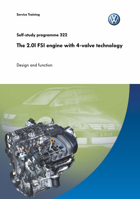
Service Training<br />
Self-study programme <strong>322</strong><br />
<strong>The</strong> <strong>2.0l</strong> <strong>FSI</strong> <strong>engine</strong> <strong>with</strong> 4-<strong>valve</strong> <strong>technology</strong><br />
Design and function
<strong>The</strong> <strong>2.0l</strong> <strong>engine</strong> is based on the tried and tested<br />
827/113 series.<br />
Thanks to <strong>FSI</strong> <strong>technology</strong> (Fuel Stratified<br />
Injection), the <strong>2.0l</strong> petrol <strong>engine</strong> has taken on a<br />
new dimension. <strong>FSI</strong> <strong>engine</strong>s are more economic,<br />
cleaner and more responsive than multi-point<br />
injection <strong>engine</strong>s.<br />
<strong>The</strong>y also meet today’s requirements in terms of<br />
low consumption, environmental issues and<br />
increased driving fun.<br />
<strong>The</strong> Volkswagen 1.4-litre/77kW <strong>FSI</strong> <strong>engine</strong>, the<br />
pioneer in this new generation of petrol <strong>engine</strong>s,<br />
demonstrated these advantages at the end of<br />
2000 when it was used in the Lupo. It was then<br />
followed by the 1.6-litre/81kW <strong>FSI</strong> and 1.4-litre/<br />
63kW <strong>FSI</strong> in the Polo.<br />
This self-study programme should familiarise you<br />
<strong>with</strong> the new technical features of this <strong>engine</strong>.<br />
S<strong>322</strong>_015<br />
NEW<br />
Important<br />
Note<br />
<strong>The</strong> self-study programme shows the design and<br />
function of new developments.<br />
<strong>The</strong> contents will not be updated.<br />
For current testing, adjustment and repair instructions,<br />
refer to the relevant service literature.<br />
2
Contents<br />
Introduction . . . . . . . . . . . . . . . . . . . . . . . . . . . . . . . . . . 4<br />
Engine mechanics . . . . . . . . . . . . . . . . . . . . . . . . . . . . . 6<br />
Engine management. . . . . . . . . . . . . . . . . . . . . . . . . . 10<br />
Functional diagram. . . . . . . . . . . . . . . . . . . . . . . . . . . . 18<br />
Service . . . . . . . . . . . . . . . . . . . . . . . . . . . . . . . . . . . . . 20<br />
Test yourself . . . . . . . . . . . . . . . . . . . . . . . . . . . . . . . . . 22<br />
3
Introduction<br />
Description of <strong>engine</strong><br />
Using the Volkswagen Audi platform, the 2.0-litre <strong>FSI</strong> <strong>engine</strong> appeared for the first time in the Audi A4,<br />
longitudinally mounted <strong>with</strong> the <strong>engine</strong> code AWA. In February 2003, the <strong>2.0l</strong> <strong>FSI</strong> <strong>engine</strong> <strong>with</strong> the code<br />
AXW, identical <strong>with</strong> the Volkswagen version, was installed transversely in the Audi A3.<br />
<strong>The</strong> following components have been further developed to meet the high demands for <strong>engine</strong><br />
performance and economy:<br />
● An aluminium <strong>engine</strong> block <strong>with</strong><br />
cast-iron liners<br />
● A water-cooled exhaust gas recirculation<br />
<strong>valve</strong> (EGR)<br />
● An exhaust system <strong>with</strong> two starter catalytic<br />
converters fitted close to the <strong>engine</strong><br />
Exhaust gas<br />
recirculation <strong>valve</strong><br />
S<strong>322</strong>_051<br />
Starter catalytic converters<br />
Engine block<br />
S<strong>322</strong>_049<br />
4
● An intake manifold <strong>with</strong> change-over barrel for switching between the torque and power channels<br />
● A new oil filter module<br />
● Bosch Motronic MED 9.5.10<br />
● Four <strong>valve</strong>s per cylinder, operated via roller rocker fingers <strong>with</strong> upright hydro-elements<br />
● Aluminium cylinder head <strong>with</strong> two overhead camshafts and continuous inlet camshaft timing<br />
adjustment<br />
● Direct fuel injection <strong>with</strong> demand-regulated high-pressure pump<br />
Camshafts<br />
Roller rocker arm<br />
Valves<br />
S<strong>322</strong>_069<br />
S<strong>322</strong>_073<br />
Change-over<br />
barrel<br />
Intake manifold<br />
Oil filter module<br />
S<strong>322</strong>_047<br />
S<strong>322</strong>_071<br />
5
Engine mechanics<br />
<strong>The</strong> <strong>2.0l</strong>/110kW <strong>FSI</strong> <strong>engine</strong> <strong>with</strong> 4-<strong>valve</strong> <strong>technology</strong><br />
<strong>The</strong> <strong>2.0l</strong>/110kW <strong>FSI</strong> <strong>engine</strong> was used in the Audi A3 in February 2003. Volkswagen used the <strong>engine</strong> for<br />
the first time in October 2003 in the Touran. It will be available for the Golf from the start of 2004.<br />
Technical features<br />
● Single-piston high-pressure pump<br />
● Plastic variable intake manifold<br />
● Intake manifold <strong>with</strong> continuously<br />
adjustable charge direction flaps/<br />
intake manifold flaps<br />
● Water-cooled exhaust gas recirculation <strong>valve</strong><br />
● Roller rocker finger <strong>with</strong> hydraulic<br />
support element<br />
● Two overhead camshafts <strong>with</strong> continuous inlet<br />
camshaft adjustment<br />
● Balancer shaft gear assembly in sump<br />
● Air-guided combustion method<br />
S<strong>322</strong>_011<br />
Technical data<br />
Torque and power diagram<br />
Engine code<br />
AXW<br />
Type<br />
4-cylinder in-line <strong>engine</strong><br />
Displacement [mm³] 1984<br />
Bore [mm] 82.5<br />
220<br />
200<br />
180<br />
110<br />
100<br />
90<br />
Stroke [mm] 92.8<br />
Valves per cylinder 4<br />
Compression ratio 11.5:1<br />
Maximum output 110kW at 6000rpm<br />
Maximum torque 200Nm at 3500rpm<br />
Engine management Bosch Motronic MED 9.5.10<br />
Fuel<br />
Unleaded 98 RON<br />
(Unleaded 95 RON <strong>with</strong><br />
reduction in performance)<br />
Exhaust gas treatment NO x storage catalytic<br />
converter and 2 starter<br />
catalytic converters<br />
Emissions standard EU 4<br />
Torque [Nm]<br />
160<br />
140<br />
120<br />
100<br />
80<br />
60<br />
40<br />
20<br />
1000 3000 5000<br />
Engine speed [rpm]<br />
80<br />
70<br />
60<br />
50<br />
40<br />
30<br />
20<br />
10<br />
7000<br />
Power [kW]<br />
S<strong>322</strong>_012<br />
6
Intake manifold <strong>with</strong> change-over barrel<br />
<strong>The</strong> two-stage variable intake manifold helps provide the required power and torque characteristics.<br />
<strong>The</strong> pneumatic switching of the change-over barrels from torque to power position is map-controlled.<br />
<strong>The</strong> load, speed and temperature are the relevant variables for this process.<br />
Change-over barrel<br />
<strong>The</strong> change-over barrel in power position.<br />
<strong>The</strong> <strong>engine</strong> draws in air via the power channel<br />
and the torque channel.<br />
Power channel<br />
S<strong>322</strong>_065<br />
Torque channel<br />
<strong>The</strong> change-over barrel in torque position. <strong>The</strong><br />
<strong>engine</strong> draws in air only via the torque channel.<br />
S<strong>322</strong>_067<br />
7
Engine mechanics<br />
Intake manifold lower part<br />
<strong>The</strong> lower part of the intake manifold contains four intake manifold flaps that are adjusted by the V157<br />
control motor via a common shaft. <strong>The</strong> G336 potentiometer integrated in the control motor is used<br />
to indicate the flap position to the J220 <strong>engine</strong> control unit.<br />
S<strong>322</strong>_061<br />
<strong>The</strong> oil filter module<br />
Crankcase breather<br />
<strong>The</strong> new oil filter module was developed as a<br />
highly integrated plastic unit. Its components<br />
include:<br />
damper chamber<br />
Oil outlet<br />
- An oil pressure shut-off <strong>valve</strong><br />
- A paper filter element to filter the oil<br />
- An integrated water-cooled oil cooler<br />
- A damper chamber on the crankcase<br />
breather for the liquid-vapour separator<br />
Water<br />
inlet<br />
Oil inlet<br />
Oil cooler<br />
Water<br />
outlet<br />
Oil pressure shut-off <strong>valve</strong><br />
Paper filter element<br />
S<strong>322</strong>_045<br />
Oil drainage <strong>valve</strong><br />
8
<strong>The</strong> cylinder head<br />
<strong>The</strong> <strong>2.0l</strong> <strong>FSI</strong> <strong>engine</strong> <strong>with</strong> 4-<strong>valve</strong> <strong>technology</strong> has<br />
an aluminium cylinder head.<br />
<strong>The</strong> <strong>valve</strong>s are operated by two overhead<br />
camshafts mounted on bearings in a ladder<br />
frame to ensure torsional stiffness.<br />
<strong>The</strong> outlet camshaft is driven by toothed belts.<br />
<strong>The</strong> inlet camshaft is driven via the outlet<br />
camshaft by a simplex chain.<br />
Each intake channel is divided into an upper and<br />
lower half by a separating plate. <strong>The</strong> plates have<br />
been shaped so that they can only be fitted in the<br />
correct position.<br />
Ladder frame<br />
Outlet camshaft<br />
Inlet camshaft<br />
Separating plate<br />
S<strong>322</strong>_059<br />
9
Engine management<br />
System overview<br />
G71<br />
G42<br />
Intake manifold pressure sender<br />
Intake air temperature sender<br />
Diagnosis connector<br />
G299 Intake air temperature sender 2<br />
G28<br />
Engine speed sender<br />
G40<br />
Hall sender<br />
J338 Throttle <strong>valve</strong> module<br />
G187 Throttle <strong>valve</strong> drive angle sender 1<br />
G188 Throttle <strong>valve</strong> drive angle sender 2<br />
J220 Motronic<br />
control unit<br />
G79 Accelerator pedal position sender<br />
G185 Accelerator pedal position sender 2<br />
F<br />
F47<br />
Brake light switch<br />
Cruise control system brake pedal switch<br />
G247 Fuel pressure sender, high pressure<br />
G410 Fuel pressure sender, low pressure<br />
G61 Knock sensor<br />
G66 Knock sensor 2<br />
G62<br />
Coolant temperature sender<br />
G83 Radiator outlet coolant<br />
temperature sender<br />
G336 Intake manifold flap potentiometer<br />
Communications line<br />
CAN drive<br />
G212 Exhaust gas recirculation potentiometer<br />
G39 Lambda probe<br />
G108 Lambda probe II<br />
G130 Lambda probe after catalytic converter<br />
G131 Lambda probe II after catalytic converter<br />
G235 Exhaust gas temperature sender<br />
G295 NOx sender<br />
J583 NOx sensor control unit<br />
G294 Brake servo pressure sensor<br />
G476 Clutch position sender<br />
J519<br />
J533<br />
Onboard supply control<br />
unit<br />
Data bus diagnostic<br />
interface<br />
10
J538<br />
G6<br />
Fuel pump control unit<br />
Fuel pump<br />
N30 Injector, cylinder 1<br />
N31 Injector, cylinder 2<br />
N32 Injector, cylinder 3<br />
N33 Injector, cylinder 4<br />
N70 Ignition coil 1 <strong>with</strong> output stage<br />
N127 Ignition coil 2 <strong>with</strong> output stage<br />
N291 Ignition coil 3 <strong>with</strong> output stage<br />
N292 Ignition coil 4 <strong>with</strong> output stage<br />
J338 Throttle <strong>valve</strong> module<br />
G186 Throttle <strong>valve</strong> drive<br />
J271<br />
Motronic current supply relay<br />
J527<br />
J234<br />
J104<br />
Steering column<br />
electronics<br />
control unit<br />
Airbag<br />
control unit<br />
ABS<br />
control unit<br />
N276 Fuel pressure regulating <strong>valve</strong><br />
N80 Activated charcoal filter system solenoid <strong>valve</strong><br />
N316 Intake manifold flap air flow control <strong>valve</strong><br />
N18<br />
Exhaust gas recirculation <strong>valve</strong><br />
Z19<br />
Lambda probe heater<br />
Z28<br />
Lambda probe 2 heater<br />
Z29<br />
Lambda probe 1 heater after catalytic converter<br />
Z30<br />
Lambda probe 2 heater after catalytic converter<br />
J285<br />
Control unit <strong>with</strong><br />
display in<br />
dash panel insert<br />
Z44<br />
NOx sender heater<br />
N205 Inlet camshaft timing adjustment <strong>valve</strong><br />
V157<br />
Intake manifold flap motor<br />
S<strong>322</strong>_042<br />
11
Engine management<br />
Exhaust system<br />
<strong>The</strong> front section of the exhaust system is split into<br />
dual pipes to increase the torque in the lower rev<br />
range. Both exhaust sections are equipped <strong>with</strong><br />
starter catalytic<br />
converters.<br />
<strong>The</strong> starter catalytic converters have been<br />
permanently fixed to the two exhaust manifolds.<br />
<strong>The</strong> two exhaust sections then join together at the<br />
NOx storage catalytic converter.<br />
In lean mix operation, the storage catalytic<br />
converter temporarily stores nitric oxide (NOx).<br />
<strong>The</strong> NOx sensor monitors the degree of<br />
saturation and triggers regeneration of the<br />
storage catalytic converter.<br />
Two broadband probes monitor the mixture<br />
composition for the starter catalytic converters.<br />
Two step-type Lambda probes come after the<br />
starter catalytic converters (planar Lambda<br />
probes). <strong>The</strong>se monitor the efficiency of the<br />
starter catalytic converters.<br />
Broadband probe<br />
Starter catalytic<br />
converter<br />
S<strong>322</strong>_043<br />
Step-type Lambda<br />
probe<br />
Temperature sensor<br />
NOx sensor<br />
NOx storage catalytic<br />
converter<br />
12
Operating modes<br />
<strong>The</strong> air-guided combustion method allows use of<br />
homogenous and stratified charge modes.<br />
<strong>The</strong> <strong>engine</strong> electronics select the best operating<br />
mode depending on the load and the position of<br />
the accelerator pedal.<br />
<strong>The</strong>re are 4 main modes:<br />
- Stratified lean<br />
<strong>with</strong> exhaust gas recirculation (EGR)<br />
- Homogenous lean <strong>with</strong>out EGR<br />
- Homogenous <strong>with</strong> Lambda = 1 and EGR<br />
- Homogenous <strong>with</strong> Lambda = 1 <strong>with</strong>out EGR<br />
Homogenous<br />
Mean pressure [bar]<br />
Homogenous lean<br />
Homogenous <strong>with</strong> exhaust gas recirculation<br />
Stratified<br />
lean<br />
Engine speed [rpm]<br />
S<strong>322</strong>_040<br />
You will find further information in the self-study programme <strong>SSP</strong> 253 “<strong>The</strong> petrol direct injection<br />
system <strong>with</strong> Bosch Motronic MED 7”.<br />
13
Engine management<br />
Stratified charge mode<br />
<strong>The</strong> fuel injection, the combustion chamber<br />
geometry and the flow inside the cylinder need<br />
to be fine-tuned to make stratified charge mode<br />
possible. <strong>The</strong> following<br />
requirements also need to be met:<br />
- <strong>The</strong> <strong>engine</strong> should be in the appropriate<br />
load and rev range.<br />
- <strong>The</strong>re cannot be any exhaust gas-related<br />
errors in the system.<br />
- <strong>The</strong> coolant temperature should be above<br />
50 °C.<br />
- <strong>The</strong> temperature of the NOx storage<br />
catalytic converter should be between 250 °C<br />
and 500 °C.<br />
- <strong>The</strong> intake manifold flap should be closed.<br />
Separating plate<br />
S<strong>322</strong>_021<br />
<strong>The</strong> intake manifold flap closes the lower intake<br />
duct according to the <strong>engine</strong> map. As a result,<br />
the increased incoming mass of air has to flow<br />
through the upper intake duct and starts a<br />
tumbling charge movement in the cylinder.<br />
Intake manifold<br />
flap<br />
High-pressure<br />
injector<br />
S<strong>322</strong>_023<br />
<strong>The</strong> tumbling air flow is enhanced in the cylinder<br />
by the air-flow recess in the piston and the<br />
upwards movement of the piston.<br />
S<strong>322</strong>_025<br />
14
<strong>The</strong> fuel is injected during the compression stroke<br />
just before the ignition point. <strong>The</strong> fuel is injected<br />
at high pressure (40-110 bar) into the flow of air.<br />
<strong>The</strong> air flow then carries the ignitable mixture to<br />
the spark plug.<br />
S<strong>322</strong>_027<br />
As the injection angle is quite flat, the fuel mist<br />
virtually does not come into contact <strong>with</strong> the<br />
the piston head. This is known as an “air-guided”<br />
method.<br />
S<strong>322</strong>_029<br />
Upon combustion, there is a layer of insulating<br />
air between the ignited mixture and the cylinder<br />
wall. This reduces the amount of heat transferred<br />
via the <strong>engine</strong> block and thus improves<br />
efficiency.<br />
S<strong>322</strong>_031<br />
15
Engine management<br />
Homogenous mode<br />
In homogenous mode, the intake manifold flap is<br />
moved to an intermediate position according to<br />
the <strong>engine</strong> map.<br />
In the combustion chamber, an optimum air flow<br />
for achieving lower fuel consumption and<br />
emissions is created.<br />
S<strong>322</strong>_033<br />
In homogenous mode, the fuel is injected<br />
during the intake stroke and not in the<br />
compression phase as <strong>with</strong> stratified charge<br />
mode.<br />
S<strong>322</strong>_035<br />
16
As the fuel is injected during the intake stroke,<br />
the fuel-air mixture has more time to mix<br />
thoroughly before ignition.<br />
S<strong>322</strong>_037<br />
Combustion takes place in the whole combustion<br />
chamber <strong>with</strong>out an insulating air layer or<br />
recirculated exhaust gases.<br />
S<strong>322</strong>_039<br />
<strong>The</strong> advantages of homogenous mode are brought about by direct injection during the intake stroke.<br />
<strong>The</strong> fuel evaporation removes some of the heat from the incoming air. Cooling the interior reduces the<br />
knocking tendency and thus increases the <strong>engine</strong> compression and efficiency.<br />
17
Functional diagram<br />
J519<br />
Terminal 30<br />
Terminal 15<br />
a<br />
S<br />
S S G G6<br />
S<br />
S<br />
S<br />
N30<br />
N31<br />
N32<br />
N33<br />
G28<br />
G61<br />
G66<br />
J538<br />
G1<br />
N316<br />
N80<br />
N205<br />
N276<br />
J271<br />
J220<br />
N70<br />
N127<br />
N291<br />
N292<br />
G185<br />
G79<br />
G410<br />
J338<br />
G187<br />
G188<br />
G186<br />
b<br />
S<strong>322</strong>_052<br />
F Brake light switch<br />
F47 Cruise control system brake pedal switch<br />
G Fuel gauge sender<br />
G1 Fuel gauge<br />
G6 Fuel pump<br />
G28 Engine speed sender<br />
G39 Lambda probe<br />
G40 Hall sender<br />
G42 Intake air temperature sender<br />
G61 Knock sensor<br />
G62 Coolant temperature sender<br />
G66 Knock sensor 2<br />
G71 Intake manifold pressure sender<br />
G79 Accelerator pedal position sender<br />
G83 Radiator outlet coolant<br />
temperature sender<br />
G108 Lambda probe II<br />
G130 Lambda probe after catalytic converter<br />
G131 Lambda probe II after catalytic converter<br />
G185 Accelerator pedal position sender 2<br />
G186 Throttle <strong>valve</strong> drive<br />
G187 Throttle <strong>valve</strong> drive angle sender 1<br />
G188 Throttle <strong>valve</strong> drive angle sender 2<br />
G212 Exhaust gas recirculation potentiometer<br />
G235 Exhaust gas temperature sender<br />
G247 Fuel pressure sender, high pressure<br />
Colour code/legend<br />
= input signal<br />
= output signal<br />
= positive<br />
= earth<br />
= CAN data bus<br />
18
J519<br />
J533<br />
Terminal 30<br />
a<br />
Terminal 15<br />
S<br />
S<br />
Z44<br />
S<br />
S<br />
G295<br />
G39 Z19 Z28 G130 G108 Z29 Z30 G131 J583<br />
F47 F G476<br />
J220<br />
G62<br />
N18<br />
G212<br />
G247<br />
G42<br />
G71<br />
G40<br />
G336<br />
V157<br />
G235<br />
G83<br />
G294<br />
b<br />
S<strong>322</strong>_054<br />
G294 Brake servo pressure sensor<br />
G295 NOx sender<br />
G299 Intake air temperature sender 2<br />
G336 Intake manifold flap potentiometer<br />
G410 Fuel pressure sender, low pressure<br />
G476 Clutch position sender<br />
J271 Motronic current supply relay<br />
J338 Throttle <strong>valve</strong> module<br />
J519 Onboard supply control unit<br />
J533 Data bus diagnostic interface<br />
J538 Fuel pump control unit<br />
J583 NOx sensor control unit<br />
N18 Exhaust gas recirculation <strong>valve</strong><br />
N30 Injector, cylinder 1<br />
N31 Injector, cylinder 2<br />
N32 Injector, cylinder 3<br />
N33 Injector, cylinder 4<br />
N70 Ignition coil 1 <strong>with</strong> output stage<br />
N80 Activated charcoal filter system solenoid <strong>valve</strong><br />
N127 Ignition coil 2 <strong>with</strong> output stage<br />
N205 Inlet camshaft timing adjustment <strong>valve</strong><br />
N291 Ignition coil 3 <strong>with</strong> output stage<br />
N292 Ignition coil 4 <strong>with</strong> output stage<br />
N276 Fuel pressure regulating <strong>valve</strong><br />
N316 Intake manifold flap air flow control <strong>valve</strong><br />
V157 Intake manifold flap motor<br />
Z19 Lambda probe heater<br />
Z28 Lambda probe 2 heater<br />
Z29 Lambda probe 1 heater after catalytic converter<br />
Z30 Lambda probe 2 heater after catalytic converter<br />
Z44 NOx sender heater<br />
19
Service<br />
New special tools<br />
Designation Tool Application<br />
T10133<br />
<strong>FSI</strong> special tool<br />
case<br />
Familiar special tools for repairing <strong>FSI</strong> <strong>engine</strong>s. Also<br />
for use <strong>with</strong> <strong>2.0l</strong> <strong>FSI</strong> <strong>engine</strong>s.<br />
S<strong>322</strong>_063<br />
T40057<br />
Oil drainage<br />
adapter<br />
For draining the <strong>engine</strong> oil from the oil filter housing<br />
S<strong>322</strong>_053<br />
T40001<br />
Puller<br />
For removing the camshaft wheel<br />
T40001/6<br />
Claw attachments<br />
for<br />
puller<br />
T40001/7<br />
Claw attachments<br />
for<br />
puller<br />
S<strong>322</strong>_055<br />
20
Notes<br />
21
Test yourself<br />
1. <strong>The</strong> <strong>engine</strong> electronics select the best operating mode depending on the load and the position of the<br />
accelerator pedal. Which 4 main modes are used by the <strong>2.0l</strong> <strong>FSI</strong> <strong>engine</strong><br />
a)<br />
b)<br />
c)<br />
d)<br />
2. What is meant by the “air-led” method used in stratified charge mode<br />
a) <strong>The</strong> fuel is injected in the direction of the piston head. <strong>The</strong> fuel mist is then transported to the spark plug<br />
together <strong>with</strong> the tumble-shaped air flow.<br />
b) <strong>The</strong> fuel is injected into the tumble-shaped air flow at a flat angle and transported to the spark plug.<br />
c) <strong>The</strong> fuel directly injected during the intake stroke evaporates in the cylinder and draws part of<br />
heat from the incoming air mass.<br />
3. Where is the NOx sensor located in the exhaust system<br />
a) In front of the NOx storage catalytic converter.<br />
b) In front of the step-type Lambda probes.<br />
c) After the NOx storage catalytic converter.<br />
d) In front of the starter catalytic converters.<br />
22
Answers<br />
1.) a) Stratified injection <strong>with</strong> exhaust gas recirculation (EGR)<br />
b) Homogenous lean <strong>with</strong>out EGR<br />
c) Homogenous <strong>with</strong> Lambda = 1 and EGR<br />
d) Homogenous <strong>with</strong> Lambda = 1 <strong>with</strong>out EGR<br />
2.) b<br />
3.) c<br />
23
<strong>322</strong><br />
© VOLKSWAGEN AG, Wolfsburg, VK-36 Service Training<br />
All rights and rights to make technical alterations reserved<br />
000.2811.43.20 Technical status 10/03<br />
❀ This paper was manufactured from pulp that<br />
was bleached <strong>with</strong>out the use of chlorine.


