Part 3_Positionning equipment - Air Liquide Welding
Part 3_Positionning equipment - Air Liquide Welding
Part 3_Positionning equipment - Air Liquide Welding

Create successful ePaper yourself
Turn your PDF publications into a flip-book with our unique Google optimized e-Paper software.
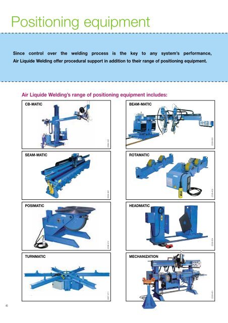
Positioning <strong>equipment</strong><br />
Since control over the welding process is the key to any system’s performance,<br />
<strong>Air</strong> <strong>Liquide</strong> <strong>Welding</strong> offer procedural support in addition to their range of positioning <strong>equipment</strong>.<br />
<strong>Air</strong> <strong>Liquide</strong> <strong>Welding</strong>’s range of positioning <strong>equipment</strong> includes:<br />
CB-MATIC<br />
BEAM-MATIC<br />
2008-402<br />
2008-393<br />
SEAM-MATIC<br />
ROTAMATIC<br />
2008-409<br />
HEADMATIC<br />
2008-354<br />
MECHANIZATION<br />
2008-401<br />
2008-391<br />
POSIMATIC<br />
2008-412<br />
TURNMATIC<br />
2007-311<br />
46
Here, just a few of the most usual configurations available to suit your working and production<br />
areas. We are always happy to develop a new solution to meet your requirements.<br />
External welds - axial and circular<br />
<strong>Welding</strong> from a moving carriage<br />
2356-055<br />
2356-057<br />
Internal welds - axial and circular<br />
Twin-boom, multi-weld - axial weld on work stand,<br />
Circular weld<br />
on rotator<br />
2356-059<br />
2356-060 2356-058<br />
2356-056<br />
<strong>Welding</strong> on a positioning table<br />
Twin-head, longitudinal welding<br />
Circular and vertical down welding on turn table<br />
Mechanization: circular welding<br />
2356-061<br />
2356-062<br />
47
Column & Booms: CB-MATIC<br />
<strong>Air</strong> <strong>Liquide</strong> <strong>Welding</strong> column and booms are the professional answer to your needs. Ideal for pressure<br />
vessels manufactured from stainless steel, mild steel and light alloy, they maximise your benefit from<br />
automatic MIG, submerged arc, TIG, plasma and plasma + TIG welding processes. Developed by the<br />
welding specialists, <strong>Air</strong> <strong>Liquide</strong> <strong>Welding</strong>'s world-reknowned technology is at your service.<br />
Standard Range:<br />
2008-394<br />
2008-360<br />
5<br />
2008-403<br />
1<br />
3<br />
2008-399<br />
2 4 6<br />
2008-404<br />
2008-402<br />
48<br />
In standard, all the column and boom are equipped with:<br />
- control panels on both main cabinet and end of the arm,<br />
- CE electrical cabinet,<br />
- full stop on motorized carriage.<br />
Designation<br />
Manual range<br />
Medium range<br />
1 LF 2 LM<br />
3 SF<br />
4 SM<br />
15 x 10 15 x 10 25 x 23 32 x 33 42 x 43 25 x 23 32 x 33 42 x 43<br />
Cat. no. W 000 315 225 W 000 315 422 W 000 315 227 W 000 315 229 W 000 315 231 W 000 315 226 W 000 315 228 W 000 315 230<br />
Displacement<br />
Vertical travel mm 1 500 1 500 2 500 3 200 4 200 2 500 3 200 4 200<br />
Arm speed cm/min manual manual 10 to 100 10 to 100 10 to 100 10 to 100 10 to 100 10 to 100<br />
Horizontal travel mm 1 000 1 000 2 300 3 300 4 300 2 300 3 300 4 300<br />
Arm speed cm/min manual manual 12 to 200 12 to 200 12 to 200 12 to 200 12 to 200<br />
Carriage speed cm/min - 57 to 570 - - - 10 to 480 10 to 480 10 to 480<br />
Height mm 2 595 2 660 4 240 4 940 5 940 4 250 4 950 5 950<br />
Maximum load<br />
at end of arm<br />
kg 70 70 200 175 150 200 175 150<br />
SF<br />
SM<br />
= Boom on fixed base with circular rotary shaft<br />
= Boom on powered carriage with circular rotary shaft<br />
LF<br />
LM<br />
= Boom on fixed base with square rotary shaft<br />
= Boom on powered carriage with square rotary shaft
Please contact our agents for any sizes or specific requirements not shown in the table.<br />
Available standard options:<br />
Customized CB-MATIC:<br />
Cable chain<br />
on arm and shaft<br />
(for LF and LM only)<br />
COLUMN AND BOOM BIG SIZE.<br />
Specific size: Consult us<br />
2008-396<br />
Bicephale <strong>equipment</strong><br />
(for LF and LM only)<br />
2008-407<br />
PERIPHERICS INTEGRATION:<br />
Seamer, positioning <strong>equipment</strong>...<br />
Consult us<br />
Different plateform<br />
for power sources<br />
2008-454<br />
2008-395<br />
Railway 3 m or 6 m<br />
2008-405<br />
Different possibilities<br />
of control panel<br />
position (on the side<br />
of the electrical<br />
cabinet or on a<br />
movable foot)<br />
SEAT OPERATOR<br />
WITH CE CERTIFICATION:<br />
Consult us<br />
Heavy range<br />
5 LF<br />
6 LM<br />
25 x 23 32 x 33 42 x 43 52 x 43 62 x 43 25 x 23 32 x 33 42 x 43 52 x 43 62 x 43<br />
W 000 315 244 W 000 315 245 W 000 315 246 W 000 315 247 W 000 315 248 W 000 315 239 W 000 315 240 W 000 315 241 W 000 3152 42 W 000 315 243<br />
2 200 3 200 4 200 5 200 6 200 2 500 3 200 4 200 5 200 6 200<br />
27 to 110 2 to 110 27 to 110 27 to 110 27 to 110 27 to 110 27 to 110 27 to 110 27 to 110 27 to 110<br />
2 300 3 300 4 300 4 300 4 300 2 300 3 300 4 300 4 300 4 300<br />
5 to 480 5 to 480 5 to 480 5 to 480 5 to 480 5 to 480 5 to 480 5 to 480 5 to 480 5 to 480<br />
- - - - - 5 to 480 5 to 480 5 to 480 5 to 480 5 to 480<br />
4 850 5 550 6 550 7 550 8 550 4 850 5 550 6 550 7 550 8 550<br />
520 460 400 400 400 520 460 400 400 400<br />
49
Seamers: SEAM-MATIC<br />
1210-067<br />
<strong>Air</strong> <strong>Liquide</strong> <strong>Welding</strong> offers a range of seamers specifically designed<br />
for horizontal welding, supporting flat or cylindrical (round or square<br />
section) workpieces with a wide range of dimensions.<br />
5 types of seamers: PL: flat sheet, FIN: small thickness, EX: external<br />
welding, IT: internal welding and EXIT: external/internal welding<br />
2008-410<br />
2008-359<br />
1<br />
2 3<br />
2008-444<br />
In standard solution:<br />
CABLE CHAIN<br />
In standard configuration :<br />
- FIN : cable chain normal<br />
- IT and EXIT: cable chain head<br />
to foot<br />
- PL and EX : cable carrying<br />
garland<br />
Possibility to have cable chain<br />
normal or head to foot in option<br />
(requested for plasma or TIG)<br />
CONTROL PANEL<br />
For all seamers, possibility<br />
to have control panel<br />
on the welding head, or on<br />
a movable foot.<br />
2008-406<br />
2008-405<br />
Customized solution:<br />
OPERATOR PLATEFORM<br />
For EX seamer: operator plateform<br />
Consult us<br />
2008-358<br />
2008-397<br />
2008-413<br />
SHEET SUPPORT<br />
For IT seamer: sheet support<br />
for in and out of the seamer<br />
Consult us<br />
OPEN DEVICE<br />
In standard, the open device is<br />
manual. For the EX seamer, there<br />
is the possibility to have<br />
a pneumatic open device.<br />
50<br />
CONTROL PEDAL<br />
Operating pedals used to<br />
open or close the clamps.<br />
2008-357
T<br />
P<br />
<strong>Welding</strong> direction 1<br />
Weldable length rules:<br />
- For mono-cathode = no difference<br />
- For bi-cathode plasma+TIG = only for welding direction 1<br />
• Inter and Exinter:<br />
up to size 52 included = – 250 mm<br />
over size 52 = – 200 mm<br />
• No difference if added video or trailer bar<br />
- consult us for:<br />
• For the other welding direction<br />
• Plasma+TIG in Exter seamer<br />
2008-361<br />
Please contact our<br />
agents for any sizes<br />
or specific<br />
requirements not<br />
shown in the table.<br />
2008-391<br />
4<br />
5<br />
Plan (PL)<br />
1<br />
Finexter (FIN)<br />
Designation<br />
Cat. no.<br />
Maximum<br />
weldable length<br />
(included run<br />
on/off plates)<br />
(mm)<br />
Workpiece specifications<br />
External<br />
welding (mm)*<br />
Internal<br />
welding<br />
(mm)*<br />
Thickness (mm)<br />
Ø mini Ø maxi Ø mini without tacking with tacking<br />
PL 22 W 000 315 132 2 250 - - - 1 to 5 1 to 8<br />
PL 32 W 000 315 133 3 250 - - - 1 to 5 1 to 8<br />
PL 42 W 000 315 134 4 250 - - - 1 to 5 1 to 8<br />
PL 52 W 000 315 135 5 250 - - - 1 to 5 1 to 8<br />
PL 62 W 000 315 136 6 250 - - - 1 to 5 1 to 8<br />
FIN 10 v 07 W 000 271 848 1 050 80 700 - 0,6 to 3 0,6 to 3<br />
2<br />
Exter (EX)<br />
3<br />
Inter (IT)<br />
4<br />
Exinter (EXIT)<br />
5<br />
EX 06 V 10 W 000 315 144 650 180 1 000 - 0.8 to 4 0.8 to 8<br />
EX 12 V 10 W 000 315 155 1 250 210 1 000 - 0.8 to 5 0.8 to 8<br />
EX 17 V 10 W 000 315 165 1 750 220 1 000 - 0.8 to 5 0.8 to 8<br />
EX 22 V 10 W 000 315 176 2 250 270 1 000 - 1 to 5 1 to 8<br />
EX 22 V 15 W 000 315 205 2 250 270 1 500 - 1 to 5 1 to 8<br />
EX 32 V 10 W 000 315 188 3 250 320 1 000 - 1 to 5 1 to 8<br />
EX 32 V 15 W 000 315 211 3 250 320 1 500 - 1 to 5 1 to 8<br />
EX 42 V 10 W 000 315 199 4 250 460 1 000 - 1 to 5 1 to 8<br />
EX 42 V 15 W 000 315 212 4 250 460 1 500 - 1 to 5 1 to 8<br />
IT 22 W 000 315 213 2 250 - - 1450 1 to 5 1 to 10<br />
IT 32 W 000 315 214 3 250 - - 1450 1 to 5 1 to 10<br />
IT 42 W 000 315 215 4 250 - - 1450 1 to 5 1 to 10<br />
IT 52 W 000 315 216 5 250 - - 1500 1 to 5 1 to 10<br />
IT 62 W 000 315 217 6 250 - - 1500 1 to 5 1 to 10<br />
IT 72 W 000 315 218 7 250 - - 1600 1 to 5 1 to 10<br />
EXIT 32 W 000 315 219 3 250 380 1450 1450 1 to 5 1 to 10<br />
EXIT 42 W 000 315 220 4 250 480 1450 1450 1 to 5 1 to 10<br />
EXIT 52 W 000 315 221 5 250 580 1500 1500 1 to 5 1 to 10<br />
EXIT 62 W 000 315 222 6 250 600 1500 1500 1 to 5 1 to 10<br />
*<br />
For other size: consult us<br />
51
Beam welding machine:<br />
BEAM-MATIC<br />
1589-003<br />
The automation of long workpieces welding (beams, wagons, box<br />
section constructions) requires sophisticated machines which move on<br />
rails.<br />
The BEAM-MATIC system is used to weld castellated welded beams of<br />
constant or varying cross-section in widths between 220 and 2 000 mm.<br />
For other dimensions, consult us.<br />
BEAM-MATIC<br />
2 types of Beam-matic are available:<br />
- PRS cantilever: CT<br />
- PRS on base column and boom: LM<br />
The beam-matic allows to weld in MIG or SAW (single or twin wire). In standard, there is push flux and flux recovery.<br />
Possibility to use wire spool or wire drum on the 2 Beam-matics.<br />
The torch level is fix on the beam-matic CT and it’s possible to lift the torch level on the Beam-matic LM.<br />
BEAM-MATIC CT<br />
2008-393<br />
BEAM-MATIC LM<br />
CLAMPING BENCH:<br />
Clamping bench allows the positioning of H beam<br />
on a mechanical structure.<br />
2008-414<br />
STANDARD DIMENSIONS FOR CLAMPING BENCH<br />
A<br />
C<br />
52<br />
2008408R<br />
* Other dimensions consult us.<br />
B<br />
Web thickness: 4 to 20 mm<br />
Flanges thickness: 10 to 30 mm<br />
A = 12000 to 24000 mm*<br />
B = 220 to 2000 mm*<br />
C = 120 to 500 mm*
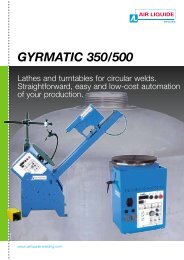
GYRMATIC<br />
2000-50/52 2000-050<br />
3100-002<br />
2000-017<br />
The GYRMATIC 350 & 500 are modular systems designed to adapt easily and<br />
quickly to all conditions for circular welding around a horizontal or vertical<br />
axis or in intermediate positions set using a manual tilt device.<br />
They are designed for manual or automatic MIG / MAG or TIG welding<br />
of circular parts secured to the turntable or between tailstocks.<br />
Example of GYRMATIC 350 assembly<br />
2008-445<br />
Mandrel<br />
Base<br />
Gyrmatic 350<br />
Support<br />
Gyrmatic<br />
Pneumatic<br />
cabinet<br />
Pneumatic<br />
slide<br />
Mast<br />
support<br />
torch<br />
Pedal<br />
Example of GYRMATIC 500 assembly<br />
2008-446<br />
Mast<br />
support<br />
torch<br />
Base<br />
Gyrmatic<br />
500<br />
Support<br />
tailstock<br />
Pneumatic slide<br />
Torch support<br />
Manual or<br />
pneumatic tailstock<br />
Mandrel<br />
Piece X support<br />
Pedal<br />
Not shown: pneumatic cabinet and electrical cabinet.<br />
1 Automatic cycle start/stop.<br />
1 1 7 Time-delays controlling overlap area and stop time<br />
3<br />
2 Manual control to start up part rotation<br />
4<br />
with direction selector.<br />
8<br />
before reset.<br />
LED display of current cycle status.<br />
3 Raise/lower torch (option).<br />
9 Adjustment of workpiece rotation speed by potentiometer<br />
4 Display of rotation speed (option).<br />
5 2<br />
6<br />
to guarantee constant, regular movement.<br />
5 Selection of part rotation direction in foot pedal<br />
10 Selection of automatic cycle mode:<br />
control mode.<br />
9<br />
7 with or without welding.<br />
6 Selection of workpiece rotation direction<br />
11 Selection of welding mode: continuous or intermittent<br />
8<br />
in automatic mode.<br />
12 Selection of one or two lathes.<br />
Technical specifications:<br />
2000-240<br />
10 12<br />
11<br />
Turntable Base GYRMATIC 350 Base GYRMATIC 500<br />
Cat. no. W 000 315 895 W 000 315 276 W 000 315 265 W 000 315 269<br />
Weld axis<br />
Rotation speed 0.9 to 18.5 tr/min 0.29 to 7.4 tr/min 0.25 to 4.5 tr/min 0.5 to 10 tr/min<br />
Number of earth clips<br />
One 250 A clip - capacity can be increased to 500 A as option<br />
Back gas option option option option<br />
Intermittent welding option option option option<br />
Mechanical specifications<br />
Machined turntable diameter Ø 350 mm Ø 350 mm Ø 490 mm Ø 490 mm<br />
Max. rotation torque 1 m/daN 2 m/daN 5 m/daN 10 m/daN<br />
Max. workpiece diameter with tailstock Ø 300 mm Ø 300 mm Ø 500 mm Ø 500 mm<br />
Max. workpiece length with tailstock 300 mm 300 mm 800 mm 800 mm<br />
Possible tilt<br />
Manual from 0° to 90° with 7 set positions at 15° intervals<br />
Dimensions / Power supply<br />
Dimensions (L x H x D) 430 x 508 x 408 mm 430 x 508 x 408 mm 600 x 1150 x 750 mm 600 x 1150 x 750 mm<br />
Power supply 230 V / 50-60 Hz 230 V / 50-60 Hz 230 V / 50-60 Hz 230 V / 50-60 Hz<br />
Unloaded weight without welding <strong>equipment</strong> 38 kg 38 kg 140 kg 140 kg<br />
53
ROTAMATIC: Single roller rotator<br />
2662-031<br />
Easy-to use line of rotators covering a load carrying range from 2 tons<br />
up to 200 tons (Drive unit + Idler unit).<br />
Medium-duty rotator: 2 T to 30 T<br />
➭ Single powered (one drive roller) for small<br />
unbalance work piece.<br />
➭ Double powered (two drive rollers) for work<br />
pieces having significant unbalance.<br />
➭ Roller-to-roller center distance adjusting by<br />
screw (except for ST 2: by step).<br />
➭ Remote pendant on all versions.<br />
➭ Possible options:<br />
• kit auto<br />
• kit display<br />
• kit ± 1% speed regulation<br />
• kit encoder 5000 pts<br />
• lorry and railway<br />
2008-409<br />
Technical specifications:<br />
Designation<br />
Cat. no.<br />
Load<br />
capacity<br />
(1 drive<br />
+ 1 idler)<br />
kg<br />
Load<br />
capacity<br />
per section<br />
kg<br />
Shell<br />
diameter<br />
mm<br />
Peripherical<br />
speed<br />
cm/min<br />
Wheel<br />
dimension<br />
OD x width<br />
Wheel<br />
material<br />
MT W 000 315 290<br />
ST 2<br />
M W 000 315 289<br />
W W 000 315 288<br />
2000 1000 30 to 2500 12 to 120 Ø 150 x 50<br />
Polyuretane<br />
F W 000 315 291 Polyamide<br />
M W 000 315 297<br />
ST 6<br />
ST 15<br />
W W 000 315 296<br />
F W 000 315 298<br />
M W 000 315 304<br />
W W 000 315 303<br />
F W 000 315 305<br />
6000 3000 300 to 3500 12 to 120 Ø 250 x 75 Polyuretane<br />
15000 7500 300 to 4000 12 to 120 Ø 250 x 110 Polyuretane<br />
54<br />
W W 000 315 309<br />
ST 30<br />
30000 15000 350 to 4500 12 to 120 Ø 350 x 150 Polyuretane<br />
F W 000 315 310<br />
Keys:<br />
M = Single motorization<br />
W = Double motorization<br />
F = Idler roll<br />
MT = Single motorization with tube system
Heavy-duty rotator: 42 T to 200 T<br />
➭ Special frame conception with built-in roll<br />
supports reduces welding height from the<br />
ground.<br />
➭ Machined bed on the idler and drive roll for<br />
perfect alignment.<br />
➭ Remote pendant, kit auto and display<br />
in standard on all versions.<br />
➭ Possible options:<br />
• lorry and railway<br />
• screw adjusting or step adjusting<br />
For a higher capacity rotators: consult us.<br />
2008-447<br />
2041-003<br />
2041-004<br />
Technical specifications:<br />
Designation<br />
Load<br />
capacity<br />
(1 drive<br />
+ 1 idler)<br />
kg<br />
Load<br />
capacity per<br />
section<br />
kg<br />
Shell<br />
diameter<br />
mm<br />
Peripherical<br />
speed<br />
cm/min<br />
Wheel<br />
dimension<br />
OD x width<br />
Wheel<br />
material<br />
LP42* 42000 21000 700 to 5000<br />
10 to 100<br />
or<br />
9 to 180<br />
Ø 400 x 200<br />
Ø 400 x 250<br />
Steel<br />
polyuretane<br />
LP55* 55000 27500 700 to 5000<br />
10 to 100<br />
or<br />
9 to 180<br />
Ø 400 x 250<br />
Ø 400 x 300<br />
Steel<br />
polyuretane<br />
LP70* 70000 35000 900 to 6000<br />
10 to 100<br />
or<br />
8 to 160<br />
Ø 460 x 250<br />
Ø 460 x 300<br />
Steel<br />
polyuretane<br />
LP100* 100000 50000 900 to 6000<br />
10 to 100<br />
or<br />
8 to 160<br />
Ø 450 x 250<br />
Ø 460 x 300<br />
Steel<br />
polyuretane<br />
LP160* 160000 80000 1200 to 6000<br />
10 to 100<br />
or<br />
9 to 160<br />
Ø 450 x 300<br />
Steel<br />
LP200* 200000 100000 1200 to 6000<br />
10 to 100<br />
or<br />
10 to 160<br />
Ø 500 x 300<br />
Steel<br />
* Available in version W (Double motorization) or F (Idler roll)<br />
55
ROTAMATIC: Fit-up rotator<br />
The fit-up rotator allows to manipulate the vessels without any other<br />
exterior elements (crank…).<br />
Up to 200 tons, with 1 set of single roller rotators (idler + motorized) and<br />
2 fit-up rotators, the operators can easily adjust the vessels in order to<br />
2570-009<br />
make a good adjustment of the shells.<br />
Fit-up rotator: 30 T to 200 T<br />
➭ In standard, the up and down movement is<br />
made by a manual hydraulic pump.<br />
➭ Possible options:<br />
• automatic hydraulic pump (hydraulic central)<br />
• lorry and railway<br />
For a higher capacity rotators: consult us.<br />
2356-063<br />
Technical specifications:<br />
Designation<br />
Load<br />
capacity<br />
(2 fit up)<br />
kg<br />
Lifting<br />
capacity<br />
per section<br />
kg<br />
Shell<br />
diameter<br />
mm<br />
Wheel<br />
dimension<br />
OD x width<br />
Wheel<br />
material<br />
Wheels<br />
adjustment<br />
TR30 30000 15000 700 to 4500 Ø 300 x 160 Polyuretane Screw<br />
TR42 42000 21000 700 to 5000 Ø 350 x 250 Polyuretane Screw<br />
TR55 55000 27500 700 to 5000 Ø 350 x 250 Polyuretane Screw<br />
TR70 70000 35000 900 to 6000 Ø 400 x 300 Polyuretane Screw<br />
TR100 100000 50000 900 to 6000 Ø 400 x 250 Steel Step<br />
TR160 160000 80000 1200 to 6000 Ø 450 x 250 Steel Step<br />
TR200 200000 100000 1200 to 6000 Ø 45 0 x 300 Steel Step<br />
1<br />
5<br />
2<br />
6<br />
3<br />
7<br />
56<br />
4<br />
Keys:<br />
= Single roller rotator motorized<br />
= Single roller rotator Idler<br />
= Fit up rotator
ROTAMATIC: Self-aligning rotator<br />
1794-052<br />
The self-aligning rotator range, up to 250 tons (Drive unit + Idler<br />
unit), allows the easy positioning of pieces.<br />
The rollers tilting allows to align the piece with the rotator<br />
without pre-adjusting of the rollers.<br />
12 T to 250 T<br />
➭ In standard: Remote pendant, kit auto<br />
and display on all versions.<br />
➭ Possible options:<br />
• lorry and railway<br />
For a higher capacity rotators: consult us.<br />
2008-356<br />
Technical specifications:<br />
Designation<br />
Load<br />
capacity<br />
(1 drive<br />
+ 1 idler)<br />
kg<br />
Load<br />
capacity<br />
per section<br />
kg<br />
Mini Shell<br />
diameter<br />
for 1/2 load<br />
mm<br />
Shell<br />
diameter for<br />
maximum<br />
load<br />
mm<br />
Peripherical<br />
speed<br />
cm/min<br />
Wheel<br />
dimension<br />
OD x width<br />
Wheel<br />
material<br />
LP12-2R* 12000 6000 500 1500 to 4000<br />
LP20-2R* 20000 10000 500 1500 to 4000<br />
LP30-2R* 30000 15000 500 1500 to 4500<br />
LP42-2R* 42000 21000 500 1500 to 5000<br />
LP55-2R* 55000 27500 800 1800 to 5000<br />
LP70-2R* 70000 35000 800 1800 to 6000<br />
LP100-2R* 100000 50000 600 1500 to 6000<br />
LP160-2R* 160000 80000 1000 1500 to 6000<br />
LP200-2R* 200000 100000 1000 1500 to 7000<br />
LP250-2R* 250000 125000 1000 1500 to 7000<br />
10 to 100<br />
or<br />
10 to 200<br />
10 to 100<br />
or<br />
10 to 200<br />
10 to 100<br />
or<br />
8 to 160<br />
10 to 100<br />
or<br />
9 to 180<br />
10 to 100<br />
or<br />
9 to 180<br />
10 to 100<br />
or<br />
9 to 180<br />
10 to 100<br />
or<br />
8 to 160<br />
10 to 100<br />
or<br />
8 to 160<br />
10 to 100<br />
or<br />
7.5 to 150<br />
10 to 100<br />
or<br />
7.5 to 150<br />
Ø 300 x 220<br />
Ø 350 x 300<br />
Ø 400 x 300<br />
Ø 400 x 400<br />
Ø 500 x 230<br />
Ø 500 x 400<br />
Ø 420 x 300<br />
Ø 460 x 300<br />
Ø 500 x 300<br />
Ø 500 x 300<br />
Ø 500 x 300<br />
Ø 550 x 400<br />
Rubber<br />
Rubber<br />
Rubber<br />
Rubber<br />
Rubber<br />
Rubber<br />
Polyuretane<br />
Polyuretane<br />
Steel<br />
Polyuretane<br />
Steel<br />
Polyuretane<br />
* Available in version W (Double motorization) or F (Idler roll)<br />
57
ROTAMATIC options<br />
Options are available to make easy the manipulation of pieces<br />
with rotators.<br />
2356-064<br />
Lorry<br />
The lorry allows to move the rotators with<br />
or without the piece.<br />
The idler lorry and the motorized lorry<br />
can be mounted on same line.<br />
2008-448<br />
For Rotators<br />
Idler lorry<br />
Motorized<br />
lorry<br />
Translation<br />
speed m/min<br />
ST 6 / ST 15 / ST 30 W 000 272 254 - -<br />
LP12-2R / LP20-2R / LP30-2R / TR30 LFC 30 - -<br />
LP42 / LP55 / LP42-2R / LP55-2R / TR42 / TR55 LFC 55 LMC 55 1,5<br />
LP70 / LP100 / LP70-2R / LP100-2R / TR70 / TR100 LFC 100 LMC 100 1,4<br />
LP160 / LP200 / LP160-2R / LP200-2R / TR160 / TR200 LFC 200 LMC 200 1,2<br />
LP250-2R LFC 250 LMC 250 1,2<br />
Antidrift system<br />
The manual antidrift device allows the piece<br />
to turn without twisting.<br />
This system is fixed on the idler rotator.<br />
Special rotators<br />
Possible to customize rotators<br />
Here example:<br />
For Rotators<br />
Manual<br />
Antidrift<br />
Device<br />
LP12-2R / LP20-2R / LP30-2R / TR30 MAD 30<br />
LP42 / LP55 / LP42-2R / LP55-2R /<br />
TR42 / TR55<br />
MAD 55<br />
LP70 / LP100 / LP70-2R / LP100-2R /<br />
TR70 / TR100<br />
MAD 100<br />
LP160 / LP200 / LP160-2R /<br />
LP200-2R / TR160 / TR200<br />
MAD 200<br />
LP250-2R MAD 250<br />
Small rotators: 6 tons, 100 to 600 mm diameter<br />
Motorized<br />
rotator<br />
Idler rotator<br />
2008-355 2356-065<br />
Fix antidrift<br />
device<br />
58
Positioners: POSIMATIC<br />
2570-014<br />
<strong>Air</strong> <strong>Liquide</strong> <strong>Welding</strong> offers a range of positioners tables of<br />
varying capacities. These devices therefore provide significant<br />
improvements in productivity, operator ergonomics and quality<br />
standards, both for manual work and for medium series<br />
production.<br />
2 types of positioners are available:<br />
• conventional: from 100 kg to 30 T<br />
• with lifting table: from 1500 kg to 10 T<br />
For higher capacity or different rotation<br />
speed range, please consult us.<br />
CE standard<br />
electrical<br />
cabinet.<br />
Swept<br />
counterweight<br />
system under<br />
the worktable.<br />
The<br />
worktable<br />
comes<br />
with various<br />
fixing slots<br />
and holes<br />
for mounting<br />
various<br />
workpieces.<br />
2008-411<br />
Cat. no.<br />
Load all<br />
positions<br />
kg<br />
Tilt<br />
torque<br />
m.kg<br />
Rotation<br />
torque<br />
m.kg<br />
Rotation<br />
speed<br />
tr/min<br />
Turntable<br />
height<br />
mm<br />
Remote<br />
control<br />
or pedal<br />
Pictures<br />
P1E 1 W 000 315 254 100 25 2 0.2 to 5 385 Pedal<br />
P2E W 000 315 256 200 40 4 0.25 to 5 500 Pedal<br />
3F W 000 315 255 400 90 20 0.14 to 2.2 650 Pedal<br />
7F 2 W 000 315 257 650 175 75 0.076 to 1.53 896 RC<br />
1<br />
2008-316<br />
16B 3 W 000 315 258 1600 400 150 0.074 to 1.48<br />
30B W 000 315 259 3000 840 250 0.06 to 1.18<br />
975<br />
to 1400<br />
980<br />
to 1380<br />
TP4 Consult us 4000 1100 500 0.045 to 0.45 1110 RC<br />
TP6 Consult us 6000 2500 720 0.03 to 0.3 1150 RC<br />
RC<br />
RC<br />
2<br />
2008-320<br />
TP8 Consult us 8000 3600 850 0.025 to 0.25 1000 RC<br />
TP10 Consult us 10000 6750 1450 0.022 to 0.22 1190 RC<br />
TP15 4 Consult us 15000 10300 2100 0.02 to 0.2 1275 RC<br />
TP20 Consult us 20000 14200 2900 0.018 to 0.18 1340 RC<br />
TP30 Consult us 30000 22500 4400 0.015 to 0.15 1450 RC<br />
4<br />
3<br />
2008-412<br />
2008-398<br />
TPE 1.5 Consult us 1500 375 160 0.06 to 0.6<br />
970<br />
to 1700<br />
RC<br />
TPE 2.5 Consult us 2500 600 200 0.06 to 0.6<br />
1030<br />
to 1850<br />
RC<br />
TPE 4 Consult us 4000 1100 500 0.045 to 0.45<br />
TPE 6 Consult us 6000 2500 720 0.035 to 0.35<br />
1060<br />
to 2010<br />
1125<br />
to 2125<br />
RC<br />
RC<br />
2008-449<br />
TPE 8 Consult us 8000 3600 850 0.025 to 0.25<br />
TPE 10 Consult us 10000 6750 1450 0.022 to 0.22<br />
1125<br />
to 2125<br />
1150<br />
to 2350<br />
RC<br />
RC<br />
59
Turn-tables: TURNMATIC<br />
<strong>Air</strong> <strong>Liquide</strong> <strong>Welding</strong> propose a range of turn-table up to 30 tons. A backing gas<br />
device can complete a welding solution with column and boom and plasma<br />
welding.<br />
Turntable 5 T to 30 T<br />
A circular welding can be done by the movement of the turn table without moving the torch. In the standard<br />
range, a turn table can make the rotation of shells up to 30 tons and up to 4500 mm diameter.<br />
For other sizes, capacities or rotation speed range: consult us.<br />
2008-451<br />
2007-311<br />
2008-362<br />
1467-003<br />
Designation<br />
Load<br />
capacity<br />
kg<br />
Mini Shell<br />
diameter<br />
mm<br />
Maxi Shell<br />
diameter<br />
mm<br />
Rotation<br />
speed<br />
tr/min<br />
Turnmatic 5 T 5000 1200 4500 0,004 to 0,204<br />
Turnmatic 10 T 10000 1000 4500 0,004 to 0,204<br />
Turnmatic 20 T 20000 1000 4500 0,004 to 0,204<br />
Turnmatic 30 T 30000 1000 4500 0,004 to 0,204<br />
Backing gas device:<br />
The backing gas device mounted on turn table,<br />
complete the turn-key solution of plasma<br />
welding column and boom.<br />
A man hole in the turn table allows the operator<br />
to adjust the backing gas device inside the shell.<br />
60<br />
2008-450<br />
For other sizes, capacities<br />
or rotation speed range:<br />
consult us.
Headstock: HEADMATIC<br />
2008-400<br />
A complete range of headstock allows the rotation piece<br />
in horizontal position.<br />
Headstock:<br />
The headstock range allows to make rotations of<br />
piece up to 3 tons.<br />
2 types of headstock:<br />
• MINITOP, TOP and SUPERTOP to be integrated<br />
on a mechanization<br />
• H range for manual manipulation or integrated on<br />
machine.<br />
F1<br />
C1<br />
C2<br />
1<br />
2<br />
2008-400 2008-354<br />
Designation<br />
Motorized<br />
Cat. no.<br />
Idler<br />
Cat. no.<br />
Flat Load<br />
capacity<br />
(F1) kg<br />
Rotation<br />
torque<br />
(C1) m.kg<br />
Tilting<br />
torque<br />
(C2) m.kg<br />
Rotation<br />
speed<br />
tr/min<br />
MINITOP 26.8 tr W 000 315 429<br />
50 3.6 14 2.7 to 26.8<br />
MINITOP 8.25 tr W 000 315 427 W 000 315 426 50 9.4 14 0.82 to 8.25<br />
MINITOP 3.75 tr W 000 315 425 50 16 14 0.37 to 3.75<br />
TOP W 000 315 371 W 000 315 367 300 15 90 0.05 to 4.5<br />
SUPERTOP 1 W 000 315 397 W 000 315 402 1000 45 300 0.05 to 5<br />
H 0.7 (700 kg) HM 0.7 HF 0.7 - 70 210 0.1 to 2<br />
H 1.5 (1500 kg) 2 HM 1.5 HF 1.5 - 150 450 0.07 to 1.4<br />
H 3 (3000 kg) HM 3 HF 3 - 300 900 0.06 to 1.2<br />
61
Mechanization<br />
<strong>Air</strong> <strong>Liquide</strong> welding proposes to design machines with modular elements in order to build the<br />
machine around to piece to be welded or cut. The mechanization allows to safe time for your<br />
project of machine.<br />
Machine design<br />
Machine realization<br />
2356-066<br />
2008-401<br />
A large choice of mechanization parts<br />
Beam,<br />
carriage,<br />
manual<br />
or<br />
motorized<br />
slides…<br />
2356-067<br />
Oscillation<br />
mechanism…<br />
2008-452<br />
Headstock,<br />
tailstock,<br />
rotation block,<br />
mandrel…<br />
X rotators,<br />
support<br />
blocks,<br />
command box<br />
supports…<br />
2008-400<br />
2008-400<br />
Sensortrack<br />
probe,<br />
laserprobe,<br />
mechanical<br />
tracking…<br />
1202-055<br />
Mecacycle,<br />
electrical<br />
cabinet…<br />
1806-055<br />
62
Headstock mechanization<br />
on CTP2 beam<br />
SAW plateform<br />
for school training<br />
2008-417<br />
0200-029<br />
2008-416<br />
2008-453<br />
Plasma mechanization HPW for pipes welding<br />
Double MIG mechanization<br />
for unless screw welding<br />
2008-415<br />
MIG gantry<br />
for aluminium<br />
train welding<br />
63