HP Virtual Connect for the Cisco Network Administrator
HP Virtual Connect for the Cisco Network Administrator
HP Virtual Connect for the Cisco Network Administrator

Create successful ePaper yourself
Turn your PDF publications into a flip-book with our unique Google optimized e-Paper software.
20<br />
creates <strong>the</strong> SUS, adds one or more VC uplinks, defines which VLAN tags are carried on <strong>the</strong> VC<br />
uplinks and <strong>the</strong>n provides a vNet name (ASCII) <strong>for</strong> each of <strong>the</strong> VLANs defined. This means that<br />
<strong>the</strong> uplink ports within <strong>the</strong> SUS provide external connectivity <strong>for</strong> multiple vNets. In o<strong>the</strong>r words,<br />
one or more vNets share a set of uplinks <strong>for</strong> external network connectivity. This is why <strong>the</strong> term<br />
“Shared Uplink Sets” is used. See VC Uplink 2 in <strong>the</strong> figure below.<br />
When VC uplink ports are assigned to a single vNet and connected to an external switch<br />
port in VLAN trunking mode, <strong>the</strong> VC uplink and vNet operate in VLAN\CoS tunneling mode or<br />
dot1qtunnel mode by default. In o<strong>the</strong>r words, <strong>the</strong> vNet keeps all frames within <strong>the</strong> same layer 2<br />
domain (vNet), however, VC allows <strong>the</strong> frames to carry different VLAN tags from <strong>the</strong> external<br />
network all <strong>the</strong> way to <strong>the</strong> server NIC ports and vice versa. See VC Uplink 3 in <strong>the</strong> figure below.<br />
When multiple vNETs are provisioned to a downlink a VLAN trunk is created <strong>for</strong> that connection.<br />
The VLANs used can be from any uplinks within <strong>the</strong> <strong>Virtual</strong> <strong>Connect</strong> Domain. Up to 162 vNets<br />
can be configured as part of this VLAN trunk. The server OS must be configured to handle<br />
tagged traffic.<br />
Shared Uplink Sets manage uplink redundancy <strong>the</strong> same as individual vNets do. In o<strong>the</strong>r<br />
words, when multiple uplinks are assigned to a Shared Uplink Set, <strong>the</strong> uplinks can operate in<br />
failover-only mode or <strong>the</strong>y can operate in port channeling (E<strong>the</strong>rchannel) mode. Also, all VLANs<br />
and associated vNets within a single Shared Uplink Set use <strong>the</strong> same active uplink or same<br />
active port channel.<br />
Note:<br />
For sample configurations with VC connected to a <strong>Cisco</strong> switch configured <strong>for</strong> VLAN trunking,<br />
see <strong>Virtual</strong> <strong>Connect</strong> E<strong>the</strong>rnet Cookbook: http://www.hp.com/go/bladesystem/documentation under<br />
<strong>the</strong> “Installing” tab. The <strong>Cisco</strong> switch commands are <strong>the</strong> same <strong>for</strong> VC in VLAN Trunking mode or<br />
VC in VLAN Tunneling mode.<br />
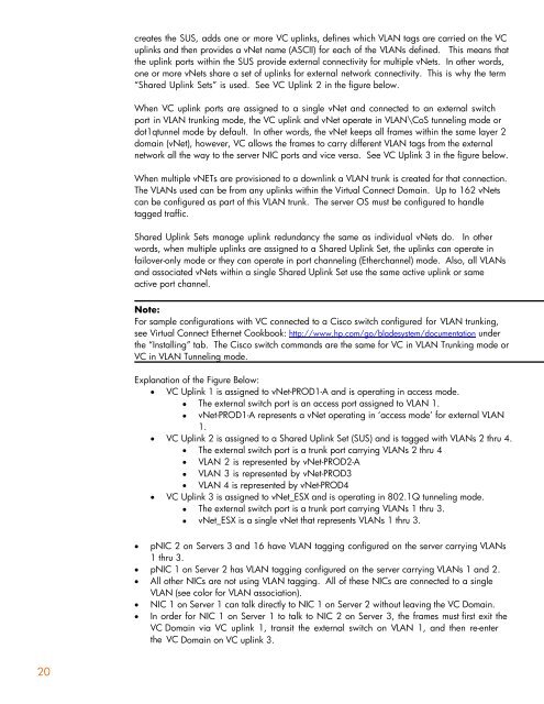
Explanation of <strong>the</strong> Figure Below:<br />
� VC Uplink 1 is assigned to vNet-PROD1-A and is operating in access mode.<br />
� The external switch port is an access port assigned to VLAN 1.<br />
� vNet-PROD1-A represents a vNet operating in „access mode‟ <strong>for</strong> external VLAN<br />
1.<br />
� VC Uplink 2 is assigned to a Shared Uplink Set (SUS) and is tagged with VLANs 2 thru 4.<br />
� The external switch port is a trunk port carrying VLANs 2 thru 4<br />
� VLAN 2 is represented by vNet-PROD2-A<br />
� VLAN 3 is represented by vNet-PROD3<br />
� VLAN 4 is represented by vNet-PROD4<br />
� VC Uplink 3 is assigned to vNet_ESX and is operating in 802.1Q tunneling mode.<br />
� The external switch port is a trunk port carrying VLANs 1 thru 3.<br />
� vNet_ESX is a single vNet that represents VLANs 1 thru 3.<br />
� pNIC 2 on Servers 3 and 16 have VLAN tagging configured on <strong>the</strong> server carrying VLANs<br />
1 thru 3.<br />
� pNIC 1 on Server 2 has VLAN tagging configured on <strong>the</strong> server carrying VLANs 1 and 2.<br />
� All o<strong>the</strong>r NICs are not using VLAN tagging. All of <strong>the</strong>se NICs are connected to a single<br />
VLAN (see color <strong>for</strong> VLAN association).<br />
� NIC 1 on Server 1 can talk directly to NIC 1 on Server 2 without leaving <strong>the</strong> VC Domain.<br />
� In order <strong>for</strong> NIC 1 on Server 1 to talk to NIC 2 on Server 3, <strong>the</strong> frames must first exit <strong>the</strong><br />
VC Domain via VC uplink 1, transit <strong>the</strong> external switch on VLAN 1, and <strong>the</strong>n re-enter<br />
<strong>the</strong> VC Domain on VC uplink 3.