PKG-EMJ04-EDC04-CBLS Spec Sheet.pdf - Anaheim Automation
PKG-EMJ04-EDC04-CBLS Spec Sheet.pdf - Anaheim Automation
PKG-EMJ04-EDC04-CBLS Spec Sheet.pdf - Anaheim Automation

You also want an ePaper? Increase the reach of your titles
YUMPU automatically turns print PDFs into web optimized ePapers that Google loves.
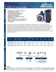
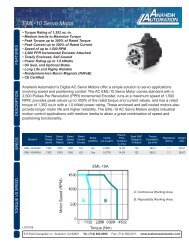
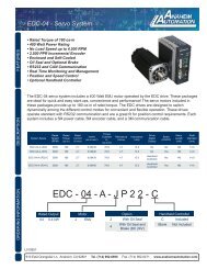
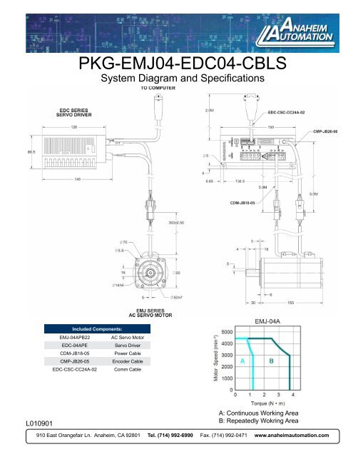
<strong>PKG</strong>-<strong>EMJ04</strong>-<strong>EDC04</strong>-<strong>CBLS</strong><br />
System Diagram and <strong>Spec</strong>ifications<br />
Included Components:<br />
EMJ-04APB22 AC Servo Motor<br />
EDC-04APE<br />
Servo Driver<br />
CDM-JB18-05<br />
Power Cable<br />
CMP-JB26-05<br />
Encoder Cable<br />
EDC-CSC-CC24A-02 Comm Cable<br />
L010901<br />
A: Continuous Working Area<br />
B: Repeatedly Wokring Area<br />
910 East Orangefair Ln. <strong>Anaheim</strong>, CA 92801 Tel. (714) 992-6990 Fax. (714) 992-0471 www.anaheimautomation.com
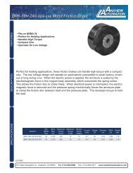
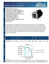
EMJ-04APB22 60mm AC Servo Motor<br />
FEATURES<br />
• Rated Torque of 180 oz.-in.<br />
• Medium Inertia to Maximize Torque<br />
• Peak Torque up to 300% of Rated Torque<br />
• Peak Current up to 300% of Rated Current<br />
• No Load Speed of up to 4,500 RPM<br />
• 2,500 PPR Incremental Encoder Attached<br />
• Enclosed and Self-Cooled<br />
• Power Ratings up to 400 Watts<br />
• Optional Brake Available<br />
• Long Life and Highly Reliable<br />
• Neodymium-Iron-Boron Magnets (NdFeB)<br />
• CE Certified<br />
DESCRIPTION<br />
<strong>Anaheim</strong> <strong>Automation</strong>’s AC servo motor offers a simple solution to servo applications. The AC<br />
Servo motor is equipped with a 2,500 counts-per-revolution encoder. The AC Servo motor enables<br />
industrial motion control applications with medium inertia to attain a great combination<br />
of speed and positioning capability. The EMJ AC Servo motor offers a cost-effective solution to<br />
many velocity and position controlled applications.<br />
SPECIFICATIONS<br />
Model #<br />
Rated<br />
Torque<br />
(oz-in)<br />
Rated<br />
Power<br />
(Watts)<br />
Max<br />
Speed<br />
(rpm)<br />
Rated<br />
Speed<br />
(rpm)<br />
Rated<br />
Current<br />
(A rms)<br />
Max<br />
Current<br />
(A rms)<br />
Power Requirement 220VAC Vibration: 49m/s 2 Running Air Pressure: 86-106 kPa<br />
Insulation Class: F Ambient Humidity: 20 to 80% RH Insulation Voltage Endurance: AC 1800V, 50Hz, 1min<br />
Ambient Temp: 0° to 40° C IP Rating: IP65 Insulation Impedance: Not Less than 50M Under Normal Conditions<br />
Running Temp: -25° to 40° C Running Humidity: Not more than 90%, under 25°C<br />
Inertia<br />
(oz-insec<br />
2 )<br />
Electric<br />
Time<br />
Constant<br />
T E<br />
(ms)<br />
Back EMF<br />
Voltage K E<br />
(V/krpm)<br />
Torque<br />
Constant K T<br />
(oz-in/A)<br />
Resistance<br />
(ohms)<br />
EMJ-04APB22 180 400 4500 3000 2.7 8.1 0.00439 2.979 31.63 79.9 4.7 5.52<br />
Weight<br />
(lbs)<br />
910 East Orangefair Ln. <strong>Anaheim</strong>, CA 92801 Tel. (714) 992-6990 Fax. (714) 992-0471 www.anaheimautomation.com
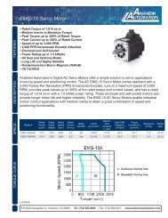
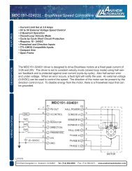
EDC Series<br />
AC Servo User’s Manual<br />
Operation of Version 2.21<br />
Preface<br />
This manual describes the operation of the <strong>Anaheim</strong> <strong>Automation</strong> servo drive type EDC and is meant for<br />
operators who are instructed for operation of the device.<br />
<strong>Anaheim</strong> <strong>Automation</strong> Limited Warranty<br />
This manual does not entitle you to any rights. <strong>Anaheim</strong> <strong>Automation</strong> reserves the right to change this manual<br />
without prior notice. All rights reserved. No part of this publication can be copied or reproduced without written<br />
permission from <strong>Anaheim</strong> <strong>Automation</strong>.<br />
- 1 -
General Precaution<br />
Power supply voltage should be AC 220V.<br />
The EDC servo system requires a power supply of AC 220V+/-15% voltage.<br />
<br />
Do not connect the servo motor directly to local electric network.<br />
It's prohibited to connect the servo motor directly to local electric network. Otherwise, the servo motor is<br />
very likely to get damaged, The servo motor will not rotate without support of servo drive.<br />
<br />
Do not plug in or unplug the connectors when the power is ON.<br />
Internal circuit and motor encoder might be damaged if you plug in or unplug during power ON. Always<br />
turn the power OFF first before plugging in or unplugging the connectors.<br />
<br />
Wait for at least 5 minutes before doing inspection work on the servo system after turning power<br />
OFF.<br />
Please note that even when the power is turned off, there will still be some electric energy remained in<br />
the capacitors of the internal circuit. In order to avoid electrical shock, please make sure inspection work<br />
is started 5 minutes after Charge indicator is OFF.<br />
<br />
There should be a space of at least 10mm between the servo drive and any other devices mounted<br />
in the electrical cabinet.<br />
The servo drive produces heat when running, heat dissipation should be considered in the design of<br />
mounting layout. At least 10 mm space in lateral direction and 50 mm space in longitudinal direction are<br />
required from servo drive to other equipment during installation. Please install the servo drive in an<br />
environment which is free from condensation, vibration and shock.<br />
<br />
Noise immunity and grounding.<br />
The noise from signal wires causes mechanical vibration and faults. Please comply with the following<br />
rules:<br />
- Run high-voltage power cables separately from low-voltage power cables.<br />
- Make cables as short as possible.<br />
- Single point grounding is required when mounting the servo motor and servo drive, and<br />
grounding resistance should be lower than 100Ω.<br />
<br />
- Please do not apply a input noise filter between servo drive and servo motor.<br />
Voltage test of the servo drive should meet following conditions:<br />
- Input voltage: AC 1500Vrms, 1 minute<br />
- Interrupt/Break current: 100mA<br />
- Frequency: 50/60Hz<br />
<br />
- Forcing point: Between Terminal R, Terminal T and Terminal E.<br />
Apply a fast-response leakage protector<br />
It’s required to use a fast-response leakage protector or a leakage protector for a PWM inverter<br />
designated by supplier. Do not use a time delay leakage protector.<br />
<br />
Avoid extreme adjustments or changes<br />
Don’t make extreme adjustments or changes to the servo drive’s parameters, which may cause<br />
mechanical vibration and result in damage.<br />
<br />
The servomotor cannot be operated by turning the power on and off.<br />
Frequently turning the power ON and OFF causes the internal circuit elements to deteriorate, resulting in<br />
unexpected problems. Always start or stop the servomotor by using reference pulses.<br />
- 2 -
Contents<br />
Preface…………………………………………………………….………………………………...-1-<br />
<strong>Anaheim</strong> <strong>Automation</strong> Limited Warranty...……………………...………………….……………..-1-<br />
General Precaution................................................................................................................ - 2 -<br />
Contents ................................................................................................................................ - 3 -<br />
Chapter 1 .............................................................................................................................. - 5 -<br />
Checking products and product specification ........................................................................ - 5 -<br />
1.1 Checking products ..............................................................................................................- 5 -<br />
1.1.1 Servo motor...............................................................................................................- 5 -<br />
1.1.2 Servo drive ................................................................................................................- 6 -<br />
1.2 Servo components description .....................................................................................- 7 -<br />
1.2.1 Servo motor...............................................................................................................- 7 -<br />
1.2.2 Servo drive ................................................................................................................- 8 -<br />
Chapter 2............................................................................................................................... - 9 -<br />
Installation..................................................................................................................................................- 9 -<br />
2.1 Servo motor ....................................................................................................................- 9 -<br />
2.1.1 Storage temperature ...........................................................................................- 9 -<br />
2.1.2 Installation site.....................................................................................................- 9 -<br />
2.1.3 Installation concentricity......................................................................................- 9 -<br />
2.1.4 Installation direction ....................................................................................- 10 -<br />
2.1.5 Handling oil and water .................................................................................- 10 -<br />
2.1.6 Cable tension ....................................................................................................- 10 -<br />
2.2 Servo drive ......................................................................................................................... - 10 -<br />
2.2.1 Storage condition .............................................................................................- 11 -<br />
2.2.2 Installation site ..................................................................................................- 11 -<br />
2.2.3 Installation orientation ......................................................................................- 11 -<br />
2.2.4 Installation of several servo drives................................................................- 12 -<br />
Chapter 3.............................................................................................................................- 13 -<br />
Wiring ..................................................................................................................................- 13 -<br />
3.1 Wiring and connection..................................................................................................- 13 -<br />
3.1.1 Typical main circuit wiring ................................................................................- 13 -<br />
3.1.2 Names and Functions of Main Circuit Terminals..........................................- 14 -<br />
3.2 I/O signals .......................................................................................................................... - 14 -<br />
3.2.1 Standard connection diagram ..........................................................................- 14 -<br />
3.2.2 Connector terminals..........................................................................................- 15 -<br />
3.2.3 Function list of I/O signals.................................................................................- 15 -<br />
3.2.4 Interface circuit example...................................................................................- 17 -<br />
3.3 Encoder wiring .............................................................................................................- 18 -<br />
3.3.1 Encoder wiring (2CN) . . . . . . . . . . . . . . . . . . . . . . . . . . . . . . . . . . . . . . . . . . . . . . . . . . . . . . . . . . . . . . . . . . . . . . . . . . . . . . . . . . . . . . . . . . . . . . . . . . . . . . . . . . . . . . . . . . . . . . . - 18 -<br />
3.3.2 Signal list of connectors (2CN) ....................................................................- 18 -<br />
3.4 Motor wiring .................................................................................................................- 19 -<br />
3.4.1 Motor encoder terminals ...................................................................................- 19 -<br />
3.4.2 Motor power terminal .......................................................................................- 19 -<br />
3.5 Standard connection example .....................................................................................- 20 -<br />
Chapter 4 ............................................................................................................................- 21 -<br />
- 3 -
Function setting and description...........................................................................................- 21 -<br />
4.1 Machine related settings .........................................................................................- 21 -<br />
4.1.1 Servomotor rotation direction Select........................................................ - 21 -<br />
4.1.2 Overtravel ......................................................................................................- 22 -<br />
4.1.3 Stop function ...................................................................................................- 23 -<br />
4.1.4 Limiting torque................................................................................................- 24 -<br />
4.2 Settings complying with host controller............................................................... - 24 -<br />
4.2.1 Position control ..............................................................................................- 26 -<br />
4.2.2 Encoder output signal ...................................................................................- 31 -<br />
4.2.3 Sequence I/O signal ......................................................................................- 33 -<br />
4.2.4 Electronic gear ...............................................................................................- 35 -<br />
4.2.5 Position contact control .................................................................................- 38 -<br />
4.2.6 Zero adjustment .............................................................................................- 41 -<br />
4.2.7 Parameter speed control...............................................................................- 44 -<br />
4.3 Servo drive settings ..................................................................................................- 46 -<br />
4.3.1 JOG speed............................................................................................................- 46 -<br />
4.3.2 Control mode selection .................................................................................- 47 -<br />
4.4 Stop function settings................................................................................................- 48 -<br />
4.4.1 Dynamic brake................................................................................................- 48 -<br />
4.4.2 Holding brake..................................................................................................- 49 -<br />
4.5 Protection design ......................................................................................................- 52 -<br />
4.5.1 Servo alarm output ........................................................................................- 52 -<br />
4.5.2 /S-ON input......................................................................................................- 53 -<br />
4.5.3 Positioning complete output .........................................................................- 54 -<br />
4.5.4 Speed reached output...................................................................................- 55 -<br />
4.5.5 Handling instant power cut ...........................................................................- 56 -<br />
4.5.6 Regenerative braking unit.............................................................................- 56 -<br />
4.6 Smooth running..........................................................................................................- 58 -<br />
4.6.1 Smoothing.............................................................................................................- 58 -<br />
4.6.2 Acceleration/deceleration time.....................................................................- 58 -<br />
4.6.3 Speed detection smoothing time constant .............................................. - 59 -<br />
4.6.4 Torque reference filter time constant...........................................................- 59 -<br />
4.7 High speed positioning .............................................................................................- 59 -<br />
4.7.1 Servo gain settings .......................................................................................- 59 -<br />
4.7.2 Speed offset settings.....................................................................................- 61 -<br />
Chapter 5......................................................................................................................- 63 -<br />
Troubleshooting ......................................................................................................................- 63 -<br />
5.1 Alarm list......................................................................................................................- 63 -<br />
5.2 Alarm outputs and Troubleshooting.........................................................................- 64 -<br />
5.3 Clearing alarms ..........................................................................................................- 67 -<br />
Chapter 6......................................................................................................................- 68 -<br />
Panel Operator ........................................................................................................................- 68 -<br />
6.1 Basic Function ..........................................................................................................- 68 -<br />
6.1.1 Function description.......................................................................................- 68 -<br />
- 4 -
6.1.2 Resetting Servo Alarms ................................................................................- 68 -<br />
6.1.3 Display mode selection .................................................................................- 69 -<br />
6.1.4 Status Display Mode ......................................................................................- 69 -<br />
6.1.5 Parameter Setting Mode...............................................................................- 72 -<br />
6.1.6 Monitor Mode..................................................................................................- 73 -<br />
6.2 Auxiliary functions ....................................................................................................- 75 -<br />
6.2.1 Alarm history display .....................................................................................- 75 -<br />
6.2.2 Restore to Defaults........................................................................................- 76 -<br />
6.2.3 JOG operation.................................................................................................- 76 -<br />
6.2.4 Automatic offset signals adjustment of motor current detection ............ - 77 -<br />
6.2.5 Servo software version display ...................................................................- 77 -<br />
6.2.6 System runtime...............................................................................................- 77 -<br />
6.2.7 Software version of panel operator.......................................................... - 78 -<br />
6.2.8 Factory test......................................................................................................- 78 -<br />
6.2.9 Inertia Tuning/Checking................................................................................- 78 -<br />
Chapter 7...................................................................................................................... - 79 -<br />
Trial operation..........................................................................................................................- 79 -<br />
7.1 Inspection and checking before trial operation ................................................. - 79 -<br />
7.2 JOG operation...........................................................................................................- 79 -<br />
7.3 Trial operation in position control mode ................................................................- 80 -<br />
Chapter 8...................................................................................................................... - 81 -<br />
Communication..............................................................................................................................- 81 -<br />
8.1 RS232 communication hardware structure..........................................................- 81 -<br />
8.1.1 External connection diagram .................................................................. - 81 -<br />
8.1.2 Cable connection ..........................................................................................- 81 -<br />
8.2 Communication relevant parameters ....................................................................- 82 -<br />
8.3 MODBUS communication protocol ......................................................................- 84 -<br />
8.3.1 Code signification...........................................................................................- 84 -<br />
8.3.2 Communication error handling.....................................................................- 90 -<br />
8.3.3 Parameters, servo status data communication address ....................... - 92 -<br />
Chapter 9...................................................................................................................... - 96 -<br />
Technical specification and features....................................................................................- 96 -<br />
9.1 Servomotor................................................................................................................- 96 -<br />
9.1.1 Technical specification and features ....................................................... - 96 -<br />
9.2 Servo drive ................................................................................................................- 98 -<br />
9.2.1 Technical specification and model...............................................................- 98 -<br />
9.2.2 Servo drive mounting dimension .................................................................- 99 -<br />
Appendix A.................................................................................................................- 100 -<br />
Parameter list.................................................................................................................- 100 -<br />
- 5 -
Chapter 1<br />
Checking products and product specification<br />
1.1 Checking products<br />
The following procedure is used to check the AC servo drivers of EDC series products on delivery.<br />
Check Items<br />
Comments<br />
Are the delivered products the ones<br />
that were ordered<br />
Check the model numbers marked on the nameplates on<br />
the servo motor and servo drive.<br />
Does the servo motor shaft rotate<br />
The servomotor shaft is normal if it can be turned<br />
smoothly by hand. Servomotors with brakes, however,<br />
smoothly<br />
cannot be turned manually.<br />
Check the overall appearance, and check for damage or<br />
Is there any damage<br />
scratches that may have occurred during shipping.<br />
If any of above items is faulty or incorrect, contact <strong>Anaheim</strong> <strong>Automation</strong>.<br />
1.1.1 Servo motor<br />
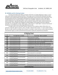
• Nameplate<br />
The following illustration shows an example of the servo motor’s nameplate.<br />
Rated output power<br />
Motor Model<br />
AC SERVO MOTOR<br />
MODEL EMJ-08APA<br />
750 W 2.39 N·M 3000 r/min<br />
4.00 A 200 V CONT. Ins. F<br />
S/N<br />
M000001Y20030409<br />
Serial No.<br />
Rated rotation speed<br />
- 5 -
• Servomotor Model Designation<br />
EMJ – 08 A P A 1 1<br />
Servomotor [1+2] [3] [4] [5] [6] [7]<br />
EMJ Model<br />
[1+2]Rated Output [4]Encoder [7]Option<br />
Code Rated Output<br />
02 200W<br />
04 400W<br />
08 750W<br />
10 1000W<br />
Code<br />
Code Designing Sequence<br />
[3]Voltage A Designing Sequence<br />
P<br />
Encoder<br />
Wire-saving Incremental<br />
Encoder(2500P/R)<br />
[5]Designing Sequence<br />
Code<br />
Option<br />
1 None<br />
2 With oil seal<br />
3 With brake(DC 24V)<br />
4 With oil seal and brake(DC 24V)<br />
Code<br />
A<br />
Voltage<br />
200VAC<br />
[6]Shaft End<br />
Code Shaft End<br />
1 Flat, Without Keys (Standard)<br />
Flat, With keys, With Screw<br />
2<br />
Thread<br />
1.1.2 Servo drive<br />
• Appearance and Nameplate<br />
- 6 -
• Servo drive Model Designation<br />
EDC – 08 A P E<br />
EDC Model Servo Drive<br />
Rated Output Power<br />
02 0.2kW<br />
04 0.4 kW<br />
08 0.75 kW<br />
10 1.0 kW<br />
Designing Sequence<br />
E Designing Sequence<br />
Control Mode<br />
P position control<br />
Voltage<br />
A 200VAC<br />
1.2 Servo components description<br />
1.2.1 Servo motor<br />
Following illustration shows the names of the components of a servo motor without gearbox<br />
and brake.<br />
Nameplate<br />
Mounting hole<br />
Encoder<br />
Output shaft<br />
Shell<br />
Flange<br />
- 7 -
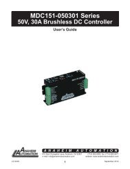
1.2.2 Servo drive<br />
Following illustration shows the connections of the servo drive.<br />
Charge indicator<br />
Lights when the main circuit power supply is ON and stays lit as<br />
long as the main circuit power supply capacitor remains<br />
charged. Therefore, do not touch the servo drive even after the<br />
power supply is turned OFF if the indicator is lit.<br />
POWER&ALARM<br />
Lights when power On, and in red when servo drive generates<br />
an alarm.<br />
CAN COM ID address selection switch<br />
Set CAN communication address<br />
CANBUS port(CAN)<br />
CAN pin out<br />
RS232 port(COM)<br />
Communicating with a digital palm operator or a computer.<br />
I/O signal connector(1CN)<br />
Used for reference input signals and sequence I/O signals.<br />
Encoder cable terminals(2CN)<br />
To connect between motor and drive.<br />
Servo motor terminals<br />
To connect with the encoder on the servo motor.<br />
Power supply terminals regenerative unit connection<br />
- 8 -
Chapter 2<br />
Installation<br />
2.1 Servo motor<br />
Servomotor can be installed either horizontally or vertically. However, if the servomotor is<br />
installed with incorrect mechanical fittings, the servo motor’s lifetime will be greatly shortened<br />
and unexpected accidents will occur.<br />
Please make installation according to the instructions as below:<br />
Precaution:<br />
There’s some antirust agent on the end of the motor shaft to prevent it from rusting during<br />
storage. Please wipe off the agent thoroughly by using a cloth dipped with diluting agent or<br />
thinners before installing the motor.<br />
NOTE: The diluting agent should not touch any other parts of the servomotor when wiping<br />
the shaft.<br />
2.1.1 Storage temperature<br />
When the servomotor is not in use, it should be kept in a place with an environment<br />
temperature between −20°C and +60°C.<br />
2.1.2 Installation site<br />
Servomotor should be installed indoors, and the environment should meet following<br />
conditions:<br />
• Free from corrosive, inflammable or explosive gases<br />
• Well ventilated and free from dust and moisture<br />
• Ambient temperature is between 0°C and 40°C<br />
• Relative humidity is between 26% and 80% RH (non-condensing)<br />
• Maintenance and cleaning can be performed easily<br />
2.1.3 Installation concentricity<br />
Use flexible shaft connectors as many as possible for mechanical connections. The axis<br />
centers of servo motor and mechanical load should be kept in the same line. If a shaft<br />
connector is used when installing servo motor, it has to meet the requirement of concentricity<br />
tolerance as shown in the illustration below.<br />
Measure this at four quarter positions of a cycle. The difference between the maximum and<br />
minimum measured value must be less than 0.03mm. (Rotate together with shaft connectors)<br />
- 9 -
Measure this at four quarter positions of a cycle. The difference between the maximum and<br />
minimum measured value must be less than 0.03mm. (Rotate together with shaft connectors)<br />
Note:<br />
• If the concentricity tolerance is too big, mechanical vibration will occur, resulting in<br />
damage to the bearings of the servo motor<br />
• Do not knock the axis direction when installing shaft connectors, this could damage the<br />
encoder of servo motor.<br />
2.1.4 Installation direction<br />
The servomotors can be installed, horizontally, vertically or in any direction.<br />
2.1.5 Handling oil and water<br />
If the servomotor is installed at a location subject to water, oil, or condensation, the motors<br />
requires special treatment to meet protection requirements. If the motors are required to meet<br />
the protection requirement before leaving the factory, it is necessary to designate the exact<br />
motor models with oil seal. Shaft- cross-section means the gap as shown in the following<br />
picture:<br />
Shaft cross section<br />
2.1.6 Cable tension<br />
When connecting the cables, the bending radius should not be to small, do not apply big<br />
pulling force to cables.<br />
Please note that the diameter of signal cable wires is very small, from 0.2 mm to 0.3 mm,<br />
therefore handle the cables with adequate care and do not cause excessive cable tension<br />
while wiring.<br />
2.2 Servo drive<br />
EDC series of servo drives are all base-mounted. Incorrect mounting will cause problems.<br />
Always mount the servo drives according to following installation instructions.<br />
- 10 -
2.2.1 Storage condition<br />
When the servo drive is not in use, it should be kept in an environment with a temperature<br />
between -20 and +85 ℃.<br />
2.2.2 Installation site<br />
Notes on installation of servo drive are as below:<br />
Condition<br />
Installed inside a control<br />
cabinet<br />
Installed near a heating unit<br />
Installed near a vibration<br />
source<br />
Installed at a site exposed<br />
to corrosive gases<br />
Other situations<br />
2.2.3 Installation orientation<br />
Safety notes<br />
A unified design for the cabinet size, configuration of servo<br />
drive, and the cooling method is required so that the<br />
ambient temperature around the servo drive is always below<br />
55 °C.<br />
Minimize the heat radiating from the units by taking<br />
advantage of heat dissipation measures such as natural<br />
convection current, forced-air cooling, to ensure working<br />
temperature around the servo drive is always below 55 °C.<br />
A vibration isolator should be mounted underneath the base<br />
surface to prevent vibration.<br />
Appropriate measures should be taken to prevent corrosive<br />
gases from getting in. Corrosive gases does not have<br />
immediate influence on the servo drive but they will<br />
eventually cause problems on electronic components, which<br />
will definitely have influence on the running stability of servo<br />
drive.<br />
Do not install the servo drive in hot, humid locations or<br />
locations subject to excessive dust or powder in the air.<br />
As shown in the following picture, the installation direction should be vertically mounted onto<br />
the wall, firmly fixed on the surface with two mounting holes.<br />
Mounting<br />
surface<br />
Ventilation<br />
A cooling fan can be mounted for forced-air cooling of the servo drive at request.<br />
- 11 -
2.2.4 Installation of several servo drives<br />
When several servo drives are required to be installed side by side inside one control cabinet,<br />
installation must be performed according to the gap requirement as shown below:<br />
Fan<br />
Fan<br />
50mm or more<br />
30mm or more<br />
10mm or more<br />
50mm or more<br />
• Installation orientation<br />
Install the servo drive vertically onto the wall so the front panel (connection board side) of<br />
servo drive faces the operator.<br />
• Cooling<br />
As shown in the illustration above, give sufficient space between each servo drive so that<br />
cooling fans or natural convection is adequate.<br />
• Side-by-side installation<br />
When installing servo drives side by side as shown in the illustration above, reserve at least 10<br />
mm between two horizontal sides and at least 50 mm between two vertical sides. The<br />
temperature in the control cabinet needs to be kept evenly distributed, subject to no<br />
overheating at any part of servo drive. If necessary, install forced-air cooling fans above the<br />
servo drives to avoid excessive temperature rise.<br />
• Normal Working Conditions for Servo Drive<br />
1. Ambient Temperature: 0 to 55°C<br />
2. Humidity: 90% RH or less, no condensing<br />
3. Vibration: 4.9 m/s2 or less<br />
To ensure a long term stability of the drive, it is suggested the drive be used in a place with a<br />
temperature below 45 °C.<br />
4. Storage condition<br />
When the servo drive is not in use, it should be kept in a place with an environment<br />
temperature between −20°C and +85°C.<br />
- 12 -
Chapter 3<br />
Wiring<br />
3.1 Wiring and connection<br />
Please observe the following instructions while wiring the main circuit.<br />
• Do not run or combine power wires and signal wires together in the same conduit. There should<br />
be at least 30 cm’s space between power wires and signal wires.<br />
• Shielded twisted pair wires are required for signal wires and encoder feedback wires, the shield<br />
layer must be connected to the shell of the plugs.<br />
Wire length requirement: reference signal input wires are maximum 3 meters, and encoder<br />
feedback wires are 20 meters to the maximum.<br />
• Please note, even when the power is turned off, there will still be some electric energy<br />
remaining in the internal circuit. In order to avoid electrical shock, please make sure inspection<br />
or wiring work is started five minutes after Charge indicator is OFF.<br />
• Do not turn power ON and OFF frequently. If required, turning power ON and OFF should be<br />
controlled only once a minute.<br />
There are some high capacity capacitors installed in the internal circuit of servo drive, when<br />
power is switched on, a high charging electric current will flow though the capacitors within<br />
several milliseconds, therefore, frequent power on/off will cause fast deteriation to the servo’s<br />
internal elements.<br />
3.1.1 Typical main circuit wiring<br />
+10%<br />
Single phase AC220V<br />
-15%<br />
50/60Hz<br />
Non-fuse circuit braker<br />
Surge<br />
suppresser<br />
Lightning protect<br />
Noise filter:<br />
Design with<br />
Europen<br />
standard<br />
Noise filter<br />
Electromagnetic<br />
contactor: Cutting off<br />
electricity supply in<br />
the emergence<br />
1MC<br />
1MC<br />
R<br />
T<br />
OFF<br />
1MC<br />
(NO)<br />
ON<br />
1RY<br />
1RY<br />
(NO)<br />
PL<br />
1MC<br />
Spark suppresser<br />
U<br />
V<br />
W<br />
Motor<br />
M<br />
Regeneration<br />
unit<br />
E<br />
P<br />
N<br />
EDC Servo drive<br />
2CN<br />
Encoder<br />
P<br />
G<br />
8<br />
18<br />
ALM<br />
COM<br />
+24V<br />
1RY<br />
0V Alarm output<br />
OFF when alarm occurs<br />
- 13 -
3.1.2 Names and Functions of Main Circuit Terminals<br />
Terminal Function Description<br />
R, T<br />
Main circuit power supply input Single-phase 220VAC(+10% / -15%) ,<br />
terminal<br />
50/60HZ<br />
U, V, W<br />
Servo Motor connection Connects to power supply terminal of<br />
terminals<br />
servo motor<br />
E Grounding terminals<br />
Connected individually to power supply<br />
grounding terminals and servo motor<br />
grounding terminal.<br />
To connect an external regenerative unit.<br />
Connection terminals of external<br />
(Note: prohibited to connect a<br />
P, N regenerative unit<br />
regenerative resistor directly between<br />
P and N.)<br />
3.2 I/O signals<br />
3.2.1 Standard connection diagram<br />
- 14 -
3.2.2 Connector terminals<br />
Pin.<br />
No.<br />
Name<br />
Description<br />
Pin.<br />
No.<br />
Name<br />
Description<br />
1 PL<br />
Power supply for<br />
open collector circuit<br />
11 PULS Reference pulse<br />
2 BRK Remain braking 12 / PULS Reference pulse<br />
3 COIN Positioning complete 13 SIGN Reference symbol<br />
4 ALM Alarm 14 /SIGN Reference symbol<br />
5 COM<br />
I/O common<br />
grounding<br />
15 S-ON Servo enabled<br />
6 ALM_RST Reset Alarm 16 +24VIN I/O power supply<br />
7 CLR Clear 17 ZPS Zero position signal<br />
8 PAO Signal A(difference) 18 /PAO Signal /A(difference)<br />
9 PBO Signal B(difference) 19 /PBO Signal /B(difference)<br />
10 PCO Signal C(difference) 20 /PCO Signal /C(difference)<br />
Shell FG Connector's shell<br />
Note:<br />
• Spare terminals can not be used for relay purpose.<br />
• Connect shielded cable wires of I/O signals to connector shell (frame grounding).<br />
3.2.3 Function list of I/O signals<br />
• Input signal (1CN)<br />
Signal Pin no. Function<br />
+24VIN 16<br />
Control power supply input for I/O signals: Users need to<br />
prepare the +24V power supply.<br />
Effective voltage range: +11V ~ +25V<br />
S-ON 15 Servo ON:Servo motor is switched on<br />
ALM-RST 6<br />
Select signal according to Pn051:<br />
(1CN-6 input signal selection)<br />
0: ALM_RST, clear servo alarm status signal<br />
1:CLR, clear offset counting in position control<br />
2:P-CON,different meanings for different control modes<br />
3:P-OT,forward direction limit signal input<br />
4:N-OT,reverse direction limit signal input<br />
CLR 7 According to Pn052, meaning as above<br />
ZPS 17<br />
Zero position signal input: zero switch outputs this signal when<br />
returning to zero position.<br />
PL 1<br />
Reference open collector power supply:<br />
To provide +5VDC power supply when PULS and SIGN<br />
reference signals are open collector input signals.<br />
PULS<br />
11 Reference pulse Input modes:<br />
/PULS<br />
SIGN<br />
/SIGN<br />
12<br />
13<br />
14<br />
input:<br />
Line drive or<br />
open collector<br />
*SIGN + Pulse train<br />
*CCW + CW Pulse<br />
*2-phase positive pulse (×4)<br />
- 15 -
• Output signal (1CN)<br />
Signal Pin no. Function<br />
ALM 4<br />
Servo alarm: OFF status output is given when the drive<br />
detects an error.<br />
COIN 3<br />
The value of Pn050 decides the output signal, see the<br />
details as follows:<br />
0: brake interlock(BK) output; positioning complete/same<br />
speed detected; in position control method it means<br />
positioning is completed(COIN), while in speed control<br />
method it means same speed is detected(V-CMP).<br />
1: positioning complete/same speed detected; in position<br />
control method it means positioning is completed(COIN),<br />
while in speed control method it means same speed is<br />
detected(V-CMP)<br />
2: torque limit CLT output: when output torque exceeds<br />
the value of Pn026 or Pn027, this signal gives output<br />
3: Servo ready S-RDY output: When servo drive detects<br />
no alarm subject to a power supply input, this signal gives<br />
output.<br />
4: Encoder C-pulse signal output: One C-pulse signal<br />
output per revolution.<br />
BK 2<br />
The value of Pn049 decides the output signal, see the<br />
details as follows:<br />
0: brake interlock(BK) output;<br />
1: positioning complete/same speed detected; in position<br />
control method it means positioning is completed(COIN),<br />
while in speed control method it means same speed is<br />
detected(V-CMP)<br />
2: torque limit CLT output: when output torque exceeds<br />
the value of Pn026 or Pn027, this signal gives output<br />
3: Servo ready S-RDY output: When servo drive detects<br />
no alarm subject to a power supply input, this signal gives<br />
output.<br />
4: Encoder C-pulse signal output: One C-pulse signal<br />
output per revolution.<br />
COM 5 I/O common grounding<br />
PAO<br />
8<br />
/PAO<br />
18<br />
Differential output of Encoder A signals<br />
PBO<br />
9<br />
/PBO<br />
19<br />
Differential output of Encoder B signals<br />
PCO<br />
10<br />
/PCO<br />
20<br />
Differential output of Encoder C signals<br />
FG<br />
Shell<br />
Connect shielded wires of I/O signal cables to shell of<br />
1CN, which is equal to the connection of the shell and the<br />
frame grounding wire.<br />
- 16 -
3.2.4 Interface circuit example<br />
Following illustrations show the connection of I/O signals of servo drive and host controller:<br />
■ Input interface circuit<br />
Following illustrations show an example of the connection of input signals using relay contact<br />
or open collector transistor circuit.<br />
Servo drive<br />
Servo drive<br />
DC24V<br />
50mA or more +24VIN<br />
3.3KΩ<br />
DC24V<br />
50mA or more<br />
+24VIN<br />
3.3KΩ<br />
/S-ON<br />
/S-ON<br />
If the relay contact input is used, the relay must be suitable for low electric current, otherwise it<br />
causes signal receiving faults.<br />
■ Interface of encoder output and drive output<br />
Output signals (PAO,/PAO,PBO,/PBO) of the two phase pulse of the encoder and the origin<br />
pulse signal(PCO, /PCO) make the outputs by means of BUS drive output circuit. Generally,<br />
it's used on the condition that the host controller side forms the position control system. Wire<br />
reception circuit should be used when it's near the host controller.<br />
See "Encoder wiring" for an example of a practical circuit connection.<br />
■ Interface of sequence output circuit<br />
Photo-coupling isolation output is required for output signals of servo alarm, positioning<br />
complete and brake interlock.<br />
DC5V~24V<br />
Relay<br />
Servo drive side<br />
0V<br />
Note:<br />
Maximum voltage should be no more than 30VDC, and maximum current should be no more<br />
than 50mA.<br />
- 17 -
3.3 Encoder wiring<br />
3.3.1 Encoder wiring (2CN)<br />
Incremental encoder<br />
4<br />
5<br />
6<br />
7<br />
8<br />
9<br />
*<br />
P<br />
P<br />
P<br />
PA<br />
/PA<br />
PB<br />
/PB<br />
PC<br />
/PC<br />
2CN<br />
2-3<br />
2-4<br />
2-1<br />
2-2<br />
2-8<br />
2-9<br />
EDC Servo drive<br />
Encoder A pulse<br />
Encoder B pulse<br />
1CN<br />
*<br />
2-8<br />
2-18<br />
PAO<br />
/PAO P<br />
2-9 PBO<br />
2-19 /PBO P<br />
(Host controller)<br />
PG<br />
Encoder C pulse<br />
Output line-drive<br />
Equivalent product of<br />
AM26LS31<br />
2-10 PCO<br />
2-20 /PCO P<br />
Line receiver<br />
equivalent product of<br />
SN75175<br />
2<br />
3<br />
PG5V<br />
GND<br />
2-7<br />
2-14<br />
PG5V<br />
PG0V<br />
1<br />
Shield wire<br />
FG<br />
Connector shell<br />
Connector shell<br />
*<br />
P<br />
Represent multi-twisted shield wire<br />
Note:<br />
The sequence No. of encoder pin’s corresponding relation with signal will change because of different types of motors .<br />
3.3.2 Signal list of connectors (2CN)<br />
See following list for description of 2CN terminals.<br />
Pin No. Name Comments Pin No. Name Comments<br />
1 PB<br />
Encoder B+<br />
Input<br />
8 PC Encoder C+ input<br />
2 /PB<br />
Encoder B-<br />
input<br />
9 /PC Encoder C- input<br />
3 PA<br />
Encoder A+<br />
input<br />
10 - --<br />
4 /PA<br />
Encoder A-<br />
input<br />
11 - --<br />
5 - -- 12 - --<br />
6 - -- 13 - --<br />
7 PG5V<br />
Encoder power<br />
Encoder power supply<br />
14 GND<br />
supply +5V<br />
grounding<br />
FG<br />
Connect shielded wires<br />
to shell of connectors.<br />
Note: Large diameter wires or multi-core wires are used for power supply and grounding.<br />
- 18 -
3.4 Motor wiring<br />
3.4.1 Motor encoder terminals<br />
3 2 1<br />
6 5 4<br />
9 8 7<br />
(View from cable side)<br />
Shell:172169-1 (AMP)<br />
Pin: 170359-3 (AMP)<br />
Incremental type<br />
Pin. No. Signal Color<br />
1 A+ Blue<br />
2 B+ Green<br />
3 C+ Yellow<br />
4 A- Blue/Black<br />
5 B- Green/Black<br />
6 C- Yellow/Black<br />
7 PG5V Red<br />
8 PG0V Black<br />
9 FG Shield<br />
Note:<br />
The corresponding relations between pin number of encoder and signal may be different for<br />
different types of motors. Please refer to the motor instructions.<br />
3.4.2 Motor power terminal<br />
Shell:172167-1 (AMP)<br />
Pin: 170360-1 (AMP)<br />
Pin NO. Signal Color<br />
1 U Red<br />
2<br />
4<br />
1<br />
3<br />
2 V Blue<br />
3 W White<br />
4 FG Green/Yellow<br />
(View from cable side)<br />
Note:<br />
The corresponding relations between pin number of motor’s power wire and signal may be<br />
different for different models of motors. Please refer to the motor instructions.<br />
- 19 -
3.5 Standard connection example<br />
Single Phase AC220<br />
50/60Hz<br />
+10%<br />
-15%<br />
Non-fuse circuit breaker<br />
Surge Lightning protect<br />
suppresser<br />
Noise filter<br />
1RY<br />
PL<br />
Noise filter:<br />
Design with<br />
European<br />
standard<br />
OFF<br />
1MC<br />
ON<br />
1RY<br />
1MC<br />
Spark suppresser<br />
1MC<br />
1MC<br />
R<br />
T<br />
U<br />
V<br />
W<br />
Motor<br />
M<br />
Regenratio<br />
n<br />
FG<br />
P<br />
N<br />
EDC Servo drive<br />
2CN<br />
Encoder<br />
P<br />
G<br />
P Represents multi-twisted wire<br />
1CN<br />
PULS 11<br />
PULS P 12<br />
/PULS<br />
SIGN 13<br />
Position SIGN<br />
reference<br />
P 14<br />
/SIGN<br />
Servo ON<br />
(Servo ON When ON)<br />
Alarm reset<br />
(Reset when ON)<br />
Clear deviation<br />
(Clear when ON)<br />
Zero point signal<br />
(Search zero position<br />
when ON)<br />
Power supply<br />
for open PL<br />
collector<br />
1<br />
150<br />
150<br />
2K<br />
18<br />
9<br />
19<br />
10<br />
20<br />
CAN<br />
FG Connector sheild<br />
Connect sheild to connector shell<br />
8<br />
Please handle connector<br />
of shield wires properly<br />
PAO<br />
/PAO<br />
PBO<br />
/PBO<br />
PCO<br />
/PCO<br />
PG dividing<br />
ratio output<br />
1 GND<br />
2 CANH<br />
3 CANL<br />
4 FG<br />
+24VIN 16<br />
COM<br />
+ 1 VCC<br />
- 3.3K 2 TXD COIN positioning complete<br />
3 RXD (ON when positioning completes)<br />
S-ON 15<br />
4 GND BK brake interlock output<br />
(ON when BK signal output)<br />
ALM-RST<br />
6<br />
3<br />
CLT torque limit output<br />
(ON when exceed preset value)<br />
*<br />
CLR<br />
S-RDY servo ready<br />
7<br />
2<br />
(ON when ready)<br />
C-Pulse Encoder C-Pulse output<br />
ZPS<br />
17<br />
+ 24V<br />
4 ALM Alarm output<br />
5<br />
0V<br />
OFF for an alarm<br />
Photocoupler:<br />
Max.Voltage DC30V<br />
Max.Current DC50mA<br />
*The functions allocated to the output<br />
signals Pin3 to Pin4 can be changed by<br />
using the parameters.<br />
- 20 -
4.1 Machine related settings<br />
4.1.1 Servomotor rotation direction Select<br />
Chapter 4<br />
Function setting and description<br />
With the servo drive, a motor can rotate in one direction which is called REV mode, without any<br />
need to make changes in motor wiring. The standard setting for “forward rotation” is the<br />
counterclockwise as viewed from motor load. REV mode only changes motor’s rotation<br />
direction, in this condition, the travel direction(+,-) of shaft rotation, no other changes are<br />
made.<br />
Standard mode<br />
Reverse mode<br />
Encoder signal<br />
feedbacked form<br />
motor<br />
Encoder signal<br />
feedbacked from<br />
motor<br />
FWD Run Ref.<br />
CCW<br />
Phase A<br />
CW<br />
Phase A<br />
Phase B<br />
Phase B<br />
Encoder signal<br />
feedbacked from<br />
motor<br />
Encoder signal<br />
feedbacked from<br />
motor<br />
REV Run Ref.<br />
CW<br />
Phase A<br />
Phase B<br />
CCW<br />
Phase A<br />
Phase B<br />
The encoder signals by motor feedback as shown in above diagrams are the PA,/PA,PB,/PB<br />
signals from PG output of servo drive.<br />
■ Set “REV mode”<br />
Rotation direction of motor is selected by setting the parameter as follows.<br />
Para.<br />
No.<br />
Pn006<br />
Name & Comments Unit Range Default<br />
Select rotation direction<br />
[0] view from side of motor load, CCW<br />
direction represents forward direction.<br />
(standard mode)<br />
[1] view from side of motor load, CW<br />
direction represents forward direction.<br />
(REV mode)<br />
— 0~1 0<br />
Note:<br />
The change only takes effect when motor power is shut down and re-powered on.<br />
- 21 -
4.1.2 Overtravel<br />
The overtravel limit function stops movable machine parts when they exceed the allowable<br />
range of motion.<br />
■ Overtravel function setting<br />
Before using overtravel function, please connect correctly the input signals of following<br />
overtravel limit switch to the corresponding pin numbers of servo drive’s 1CN connector.<br />
Input P-OT 1CN-6 Pn001=0,Pn051=3 Forward direction rotation is prohibited<br />
input N-OT 1CN-7 Pn002=0,Pn052=4 Reverse direction rotation is prohibited<br />
EDC servo drive have only one overtravel input signal (1CN-6), so users can only select<br />
overtravel limit in a single direction. Please be aware that when you are running the system<br />
for the first time it’s required to identify forward and reverse direction before making settings<br />
in the overtravel parameter.<br />
It is advised that the user connects the limit switch according to following diagram to avoid<br />
possible mechanical damage.<br />
Reverse<br />
Forward<br />
Servo drive<br />
Servo motor<br />
Limit switch<br />
P-OT<br />
N-OT<br />
1CN-6<br />
1CN-7<br />
Following table shows the drive status when input signal is ON and OFF.<br />
Signal Status Parameter Input level Comments<br />
P-OT<br />
ON<br />
Pn001=0<br />
Forward direction is allowed.<br />
1CN-6:’L’ level<br />
Pn051=3<br />
(Normal)<br />
OFF<br />
Pn001=0<br />
Forward direction is OFF. (Reverse<br />
1CN-6:’H’ level<br />
Pn051=3<br />
direction is available)<br />
N-OT<br />
Pn002=0<br />
ON<br />
1CN-7:’L’ level Reverse direction is ON. (Normal)<br />
Pn052=4<br />
Pn002=0<br />
Reverse direction is OFF. (Forward<br />
OFF<br />
1CN-7:’H’ level<br />
Pn052=4<br />
direction is available)<br />
■ Switching between Enable/Disable overtravel input signal<br />
By setting the parameter as in the following table, user may select Enable or Disable the<br />
overtravel input signal. Default is “ON”.<br />
Para.<br />
No.<br />
Pn001<br />
Pn002<br />
Description<br />
Enable/Disable input signal prohibited (P-OT)<br />
When 1CN is set as P-OT signal, limiting<br />
direction and enable are selected according to<br />
this parameter.<br />
[0] Enable forward run input signal prohibited<br />
[1] Disable forward run input signal prohibited<br />
Enable/Disable input signal prohibited (N-OT)<br />
When 1CN is set as N-OT signal, limiting<br />
direction and enabling are selected according<br />
to this parameter.<br />
[0] Enable reverse run input signal prohibited<br />
[1] Disable reverse run input signal prohibited<br />
Unit<br />
Setting<br />
range<br />
Default<br />
— 0~1 0<br />
— 0~1 0<br />
- 22 -
Notes:<br />
1. When the motor is stopped by the overtravel in position control mode, there is no pulse<br />
lag.<br />
2.After overtravel, motor is in excitation state.<br />
3. Only one overtravel direction can be used, make sure overtravel direction is set before<br />
using this function. (subject to actual running)<br />
4. Please be aware, the overtravel signal does not work if a motor is running in JOG mode.<br />
5. During mechanical movement, when an overtravel signal occurs, mechanical parts do not<br />
stop immediately owing to the action of their own inertia. In this situation, the overtravel<br />
signal is canceled and the motor will continue running. Please pay close attention to the<br />
duration of the overtravel signal, make sure there is some distance for overtravel signal on<br />
the machine.<br />
When “P-OT” and “N-OT” are not used, the short circuit wiring as shown in the following<br />
diagram will not be required. Another way is to shield this with parameter, use may set Pn001<br />
as 0 or set Pn052.bit=0.<br />
4.1.3 Stop function<br />
■ Select stop mode<br />
When servo is OFF or servo alarm occurs, the following “User Constants” should be set<br />
according to the actual requirements on stopping the motor.<br />
Parameter No. Function Range Default<br />
Pn004<br />
Stop modes when servo is on or servo<br />
alarm occurs.<br />
0~3 0<br />
Parameter No.<br />
Pn004<br />
Comments<br />
[0] When servo is OFF or alarm occurs, DB is enabled<br />
[1] When servo is OFF or alarm occurs, motor coasts to a stop<br />
[2] When servo is OFF or alarm occurs, DB is enabled and will not<br />
release until motor stops<br />
[3] When servo is OFF or alarm occurs, motor coasts to a stop, then DB<br />
is enabled.<br />
■ Select motor stop mode when servo is OFF.<br />
EDC series servo drive stop motor running in following situation:<br />
‣ When /S-ON input signal(1CN-15)turns OFF<br />
‣ When alarm is detected<br />
‣ When power supply is OFF<br />
To select appropriate stop mode, set value of Pn004 according to actual application<br />
requirements.<br />
- 23 -
4.1.4 Limiting torque<br />
For protection of mechanical structures, maximum output torque can be limited by setting the<br />
following parameters to adjust the maximum value of forward/reverse direction torque on the<br />
servo drive.<br />
Para.<br />
No.<br />
Name & Function Unit Range Default<br />
Pn026 Forward internal torque limit 1% 0~300 250<br />
Pn027 Reverse internal torque limit 1% 0~300 250<br />
• Set maximum torque for forward and reverse direction, it’s used when limiting torque<br />
is required according to mechanical requirements.<br />
• If value of current torque exceeds motor’s maximum allowable torque, follow the<br />
maximum torque of motor.<br />
Example to show protection of mechanical structures<br />
motor otor speed<br />
Torque limit<br />
Torque<br />
Note:<br />
• It’s suggested the value of limited torque should not exceed motor’s maximum torque.<br />
• If limited value is set too low, motor may have insufficient torque during its<br />
acceleration/deceleration.<br />
4.2 Settings complying with host controller<br />
Different control modes can be selected by setting Pn041 as described in the following table.<br />
Para. No. Name Range Default Comment<br />
Select control mode<br />
position control,<br />
Pn041<br />
[0] position control<br />
position contact<br />
0~2 0<br />
[1] internal speed control<br />
control, and parameter<br />
[2] parameter speed control<br />
speed control<br />
Set Pn041 and select a certain control mode.<br />
Pn041<br />
setting<br />
0<br />
1<br />
2<br />
Control mode<br />
Position control(pulse reference)<br />
Servo drive receives pulse train generated by host controller, and the control<br />
of rotation speed and positioning are achieved according to requirements<br />
from the host controller.<br />
contact speed control(I/O reference)<br />
Running at set speed is selected by switch on/off input signals.<br />
parameter speed control(parameter reference)<br />
Run at constant speed as the value in Pn048.<br />
- 24 -
Using the CLT signal<br />
Following illustration shows the way to use the contact output signal/CLT(torque limit test).<br />
Servo drive<br />
24V Power supply<br />
+24V<br />
Photocoupler<br />
Max.voltage:DC30V<br />
Max.current:DC50mA<br />
/CLT+<br />
/CLT-<br />
->output /CLT Torque limit<br />
detection output<br />
Speed control, torque<br />
control, position control<br />
The following signal can be output to indicate the servomotor output torque is being limited or<br />
not.<br />
/CLT “L” level when ON<br />
/CLT “H” level when OFF<br />
The servomotor output torque is being limited.<br />
(internal torque reference is above setting value)<br />
The servomotor output torque is not being limited.<br />
(internal torque reference is below setting value)<br />
The setting value:Pn026(Forward direction torque internal limit)<br />
Pn027(Reverse direction torque internal limit)<br />
When /CLT signal is used, the output signal and output pin number are required to be defined<br />
according to the user constants in following table.<br />
Para. No. Name & Description Range Default<br />
Pn049 Output signal 1CN-2 pin No. signification 0~4 0<br />
Pn050 Output signal 1CN-3 pin No. signification 0~4 1<br />
Servo drive<br />
Pn049=0: COIN/V-CMP<br />
Pn049=1: BK<br />
Pn049=2: CLT<br />
Pn049=3: S-RDY<br />
Pn049=4: C-Pulse<br />
Pn050=0: COIN/V-CMP<br />
Pn050=1: BK<br />
Pn050=2: CLT<br />
Pn050=3: S-RDY<br />
Pn050=4: C-Pulse<br />
1CN-2<br />
Output<br />
1CN-3<br />
The following table shows the pin number definition for Pn049(correspond to pin 1CN-2<br />
output), Pn050(correspond to pin 1CN-3output).<br />
0 BK brake interlock output<br />
1 COIN positioning complete(/V-CMP speed coincidence) output<br />
2 CLT torque limit output<br />
3 S-RDY servo ready output<br />
4 Encoder C Pulse Output(This signal couldn't be inverted)<br />
- 25 -
Please pay attention that encoder C pulse signal which is output by relative pin number will be<br />
affected by external circuit,since the signal gets through photo coupler,if Pn049 or Pn050 are<br />
selected as 4.<br />
4.2.1 Position control<br />
In position control mode(Pn041=0), the servo drive make drive runs according to the position<br />
reference given by the host controller. It is required to select optimal input according to<br />
requirements of the host control device as follows.<br />
■ Pulse input<br />
Host device controls the rotation speed and position of servo system by sending a series of<br />
pulse trains.<br />
Servo drive<br />
Photo coupler<br />
Pulse reference<br />
input<br />
PULS<br />
/PULS<br />
P<br />
1CN-11<br />
1CN-12<br />
150<br />
Pulse direction<br />
input<br />
SIGN<br />
/SIGN<br />
P<br />
1CN-13<br />
1CN-14<br />
150<br />
PRepresents multi-twisted wire<br />
Host control device may give three types of pulse reference as follows:<br />
- linear driving output<br />
- +24V open collector output<br />
- +12V and +5V open collector output<br />
Connection example 1(when host controller is linear driving output)<br />
Applicable linear drives(T1 company AM26LS3, SN75174 or MC3487 and other substitutes.)<br />
Host controller<br />
Servo drive<br />
PULS<br />
/PULS<br />
P<br />
Photo-coupler<br />
1CN-11 150<br />
1CN-12<br />
SIGN<br />
/SIGN<br />
P<br />
1CN-13<br />
1CN-14<br />
150<br />
Grounding<br />
FG<br />
Connect to<br />
shell(shielding)<br />
- 26 -
Example 2(When host device is open collector output subject to 24VDC<br />
signal power)<br />
Host controller<br />
Servo drive<br />
Vcc<br />
Photo-coupler<br />
24VDC<br />
PULS<br />
/PULS<br />
P<br />
1CN-11<br />
1CN-12<br />
150<br />
1CN-1<br />
2K<br />
SIGN<br />
/SIGN<br />
P<br />
1CN-13<br />
1CN-14<br />
150<br />
Grounding<br />
Connect to<br />
shell(shielding)<br />
FG<br />
Example 3(When host device is open collector output subject to 12VDC<br />
or 5VDC signal power)<br />
Host controller<br />
Servo drive<br />
12VDC<br />
5VDC<br />
Vcc<br />
R1<br />
PULS<br />
/PULS<br />
P<br />
i<br />
1CN-11<br />
1CN-12<br />
Photo-coupler<br />
150<br />
Vcc<br />
R1<br />
SIGN<br />
/SIGN<br />
P<br />
1CN-13<br />
1CN-14<br />
150<br />
Grounding<br />
Connect to<br />
shell(shielding)<br />
FG<br />
The right current limiting resistor R1 should be used according to current requirements(i =<br />
10~15mA):<br />
When Vcc is 12V, R1=560~820Ω<br />
When Vcc is 5V, R1=82~200Ω<br />
- 27 -
■ Selecting reference pulse mode<br />
→input PULS 1CN-11 input reference pulse<br />
→input /PULS 1CN-12 input reference pulse<br />
→input SIGN 1CN-13 input reference sign<br />
→input /SIGN 1CN-14 input reference sign<br />
Use parameter “Pn008, Pn009” to select “reference pulse mode”<br />
Parameter Code Comments Unit Range Default<br />
Pn008 --<br />
input pulse mode:<br />
[0]SIGN + pulse<br />
[1]CW+CCW<br />
-- 0~2 0<br />
[2]A+B(perpendicular × 4)<br />
Pn009 --<br />
Reference pulse form<br />
[0] does not invert PULSE<br />
reference, does not invert<br />
SIGN reference<br />
[1] does not invert PULSE<br />
reference, inverts SIGN<br />
reference<br />
[2] inverts PULSE reference,<br />
-- 0~3 0<br />
does not invert SIGN<br />
reference<br />
[3] inverts PULSE reference,<br />
inverts SIGN reference<br />
pulse input frequency selection<br />
Pn058 --<br />
[0] when pulse is difference<br />
input, servo receiving pulse<br />
frequency≤500K<br />
[1] when pulse is difference<br />
input, servo receiving pulse<br />
frequency≤300K<br />
[2] when pulse is difference<br />
input, servo receiving pulse<br />
frequency≤100K<br />
-- 0~2 0<br />
- 28 -
Following are available reference pulse styles, please make the setting according to<br />
specification of host controller.<br />
Pn008<br />
0<br />
Reference<br />
style<br />
Sign + pulse<br />
train<br />
PULS<br />
(1CN-11)<br />
SIGN<br />
(1CN-13)<br />
servomotor forward run<br />
reference<br />
“H”<br />
servomotor reverse run<br />
reference<br />
PULS<br />
(1CN-11)<br />
SIGN<br />
(1CN-13)<br />
“L”<br />
1<br />
CW pulse +<br />
CCW pulse<br />
PULS<br />
(1CN-11)<br />
SIGN<br />
(1CN-13)<br />
“L”<br />
PULS<br />
(1CN-11)<br />
SIGN<br />
(1CN-13)<br />
“L”<br />
2<br />
2 phase<br />
perpendicular<br />
pulse<br />
PULS<br />
(1CN-11)<br />
SIGN<br />
(1CN-13)<br />
0<br />
90<br />
PULS<br />
(1CN-11)<br />
SIGN<br />
(1CN-13)<br />
0<br />
90<br />
User may select to invert input signal or not by setting Pn009 according to actual requirements.<br />
■ Pulse input sequence<br />
Input of pulse reference must meet following conditions on level and sequence.<br />
Pulse form Electrical specification Remark<br />
SIGN+PULS<br />
Max. frequency: 500kpps<br />
(Open Collector :200kpps)<br />
SIGN<br />
PULS<br />
t3<br />
t4<br />
t1 t2<br />
t<br />
T<br />
Forward reference<br />
t5<br />
t7<br />
t6<br />
Reverse reference<br />
t1,t2=0.1µs<br />
t3,t7=0.1µs<br />
t4,t5,t6>3µs<br />
t=1.0µs<br />
(t /T)×100 = 50%<br />
SIGN<br />
H=Forward<br />
L=Reverse<br />
t1<br />
T<br />
CW+CCW<br />
Max. frequency:500kpps<br />
(Open Collector :200kpps)<br />
CCW<br />
CW<br />
t2<br />
t<br />
t3<br />
t1,t2=0.1µs<br />
t3>3µs<br />
t=1.0µs<br />
(t /T)×100 = 50%<br />
Forward reference<br />
Reverse reference<br />
t1<br />
t2<br />
90°phase different signal<br />
(A+B) Max. frequency:<br />
×4 multiplier :200kpps<br />
Phase A<br />
Phase B<br />
t<br />
T<br />
Forward Instruction<br />
Phase B is 90° forward<br />
from phase A<br />
Reverse Instruction<br />
Phase B is 90°<br />
behind phase A<br />
t1,t2=0.1µs<br />
t=1.0µs<br />
(t /T)×100 = 50%<br />
■ Clear error counter<br />
Follow the steps below to clear "Error counter".<br />
→input CLR 1CN-7 Clear error counter input<br />
- 29 -
When CLR signal is Low level, error counter is cleared.<br />
Way to clear error counter:<br />
- Servo drive's internal error counter is zero(0).<br />
- This signal means "power level active", it's required to retain some time before the signal<br />
takes effect. The signal has to be canceled after the pulse is cleared, otherwise, the counter is<br />
always in the zero Clear status, which will result in no action in the servo position loop.<br />
In position control mode, some pulses will remain in error counter when servo is OFF.<br />
Therefore, the error counter has to be cleared immediately after servo is re-enabled. With<br />
Pn005 setting, pulse signal of error counter can be cleared automatically when servo is OFF.<br />
Parameter<br />
No.<br />
Pn005<br />
Name and comments Setting range Default<br />
0:When S-OFF, clear error counter<br />
1:When S-OFF, does not clear<br />
error counter<br />
0~1 0<br />
■ Position reference 1st filter time<br />
‣ position reference 1st filter can improve system's respond smoothness to given reference<br />
pulse.<br />
‣ If reference input is comparatively rough, the dividing frequency multiplication is set too<br />
large or frequency of pulse input is low, which can implement more smooth control of<br />
servo system.<br />
‣ If position reference 1st filter time constant(that is Pn024)is set too large, servo system's<br />
dynamic performance will be reduced.<br />
Parameter<br />
No.<br />
Pn024<br />
Name Unit Setting range Default<br />
position reference 1st<br />
filter time constant<br />
ms 0~1000 0<br />
■ Position reference smoothing filter time<br />
Par. No. Name Unit Setting range Default<br />
Pn033<br />
position reference smoothing<br />
filter time constant<br />
ms 0~1000 0<br />
Different results between positioning after the change.<br />
position reference 1st filter time position reference smoothing filter time<br />
(Pn024)<br />
(Pn033)<br />
100%<br />
63%<br />
Before smoothing<br />
After smoothing<br />
100%<br />
37%<br />
Before smoothing<br />
After smoothing<br />
Pn024<br />
Pn024<br />
Step response waveform<br />
t<br />
Pn033<br />
Pn033<br />
Step response waveform<br />
t<br />
- 30 -
100%<br />
Pn033<br />
Before smoothing<br />
After smoothing<br />
Pn033<br />
Trapezoid reference response waveform<br />
t<br />
4.2.2 Encoder output signal<br />
The servo drive outputs pulse signal from the encoder A/B/C, which is used with the host<br />
controller.<br />
Servo drive<br />
Host controller<br />
Servo motor<br />
Encoder<br />
Phase A<br />
2CN<br />
1CN<br />
Linear drive output<br />
Phase A<br />
FG<br />
Phase B<br />
Phase B<br />
Phase C<br />
Phase C<br />
Output circuit is bus drive output. Make circuit connection with reference to following circuit.<br />
EDC Servo drive<br />
Host controller<br />
Encoder A<br />
Encoder B<br />
Encoder C<br />
*<br />
2-8<br />
2-18<br />
PAO<br />
/PAO P<br />
2-9 PBO<br />
2-19 /PBO P<br />
2-10 PCO<br />
2-20 /PCO P<br />
Line receiver<br />
R<br />
R<br />
R<br />
Linear drive output<br />
equivalent with<br />
AM26LS31<br />
Connector Shell<br />
*<br />
P<br />
Represent multi-twisted cable<br />
R=220-470<br />
■ Output signal<br />
Output encoder signal after frequency is divided.<br />
Output → PAO 1CN- 8<br />
Output → /PAO 1CN- 18<br />
A phase pulse differential Output<br />
- 31 -
Output → PBO 1CN- 9<br />
Output → /PBO 1CN- 19<br />
B phase pulse differential Output<br />
Output → PCO 1CN- 10<br />
C phase pulse differential Output<br />
Output → /PCO 1CN- 20<br />
The following illustration shows the style of perpendicular pulse output of Phase A and Phase<br />
B .<br />
Parameter Pn011=0:<br />
CCW<br />
Phase A<br />
Phase B<br />
90°<br />
CW 90°<br />
Phase A<br />
Phase B<br />
t<br />
t<br />
Parameter Pn011=1:<br />
CCW<br />
Phase A<br />
90°<br />
CW<br />
Phase A<br />
90°<br />
Phase B<br />
Phase B<br />
t<br />
t<br />
■ Set pulse dividing frequency ratio<br />
Set pulse dividing frequency ratio with following parameters.<br />
Parameter Meaning Unit Range Default<br />
Pn010<br />
Set PG dividing<br />
frequency ratio<br />
2500P/R 1~2500 2500<br />
Pn011<br />
Inverts dividing<br />
frequency output<br />
phase<br />
0~1 0<br />
Set output pulse numbers of PG output signal(PAO,/PAO,PBO,/PBO)which is transmitted<br />
outward subject to servomotor running for one revolution.<br />
Servo drive<br />
Servo motor encoder<br />
Phase A<br />
2CN<br />
1CN<br />
Linear drive output<br />
Phase A(1CN-8,1CN-18)<br />
PG<br />
Phase B<br />
Phase C<br />
Frequency<br />
Dividing<br />
Output<br />
Phase B(1CN-9,1CN-19)<br />
Phase C(1CN-10,1CN-20)<br />
Divides pulse frequency of servomotor encoder(PG) and output according to pulse number<br />
setting.<br />
Setting value means the individual output of pulse numbers for PAO, /PAO, PBO and /PBO<br />
signal when servomotor runs for one revolution. If Pn010 is set as 1000, it means output of<br />
PAO signal is 1000 pulses subject to motor runs for one revolution, so do the /PAO, PBO and<br />
- 32 -
PBO signal output.<br />
Please make setting according to the machine and reference the units of the controller.<br />
Note: After parameter changes, turn power OFF and then turn power ON again.<br />
4.2.3 Sequence I/O signal<br />
To control sequence input and output signal of the servo drive's, please connect according to<br />
your application requirements.<br />
■ Connect sequence input signal<br />
Following illustration shows how to connect the sequence input signal.<br />
EDC Servo drive<br />
+24VIN<br />
16<br />
+<br />
- 3.3K<br />
S-ON<br />
ALM-RST<br />
CLR<br />
ZPS<br />
15<br />
6<br />
7<br />
17<br />
Notes:<br />
• 24V I/O power supply is required, since there is no internal power supply servo drive.<br />
• External power supply specification: DC24V±1V, 500mA higher.<br />
• It's suggested that input circuit and output circuit use the same power supply.<br />
Voltage range of input circuit is +11V~+25V. If power voltage is low and relays are used , low<br />
value current switches or relay are required to avoid bad contact. Always check and confirm<br />
the electrical specification of the relay or relevant parts before use.<br />
input +24VIN 1CN- 16<br />
External I/O power input<br />
■ Connect contact point of output signal<br />
- 33 -
Servo drive<br />
1CN<br />
2<br />
Pn049= 0:BK 1:COIN 2:CLT<br />
3:S-RDY 4:C-Pulse<br />
IO<br />
Power supply<br />
+24V 0V<br />
Optocoupler output (each<br />
output node)<br />
Max. output voltage:30V<br />
Max. output current:50mA<br />
3<br />
4<br />
5<br />
Pn050=0:BK 1:COIN 2:CLT<br />
3:S-RDY 4:C-Pulse<br />
ALM<br />
■ Handling of I/O signals<br />
Input signals are smoothed with filters to the servo drive. Set filter time with parameter Pn053.<br />
Active power level of input signal is controlled by Pn054, and active power level of output<br />
signal is controlled by Pn055.<br />
Following signals are I/O signals subject to default parameters.<br />
Para.<br />
no.<br />
Name and meaning Unit Setting range Default<br />
Pn053 input signal filter time ms 0~1000 100<br />
Pn054 Inverts input signal - 0~15 0<br />
Pn055 Inverts output signal - 0~7 0<br />
During filter time of input signal, if signal spikes occur, input signal will not be received by servo<br />
drive. Input signal will be received by the drive only after it keeps stable for the set time, that is,<br />
signal need to keep on a constant level within period of Pn053 before it can be accepted by the<br />
servo drive. Drive estimates signal validity according to Pn054.<br />
Following table shows operations to invert input signal(Pn054).<br />
Digit BIT3 BIT2 BIT1 BIT0<br />
input signal ZPS CLR ALM-RST S-ON<br />
Signal level H L H L H L H L<br />
Pn054 0 1 0 1 0 1 0 1 0 1 0 1 0 1 0 1<br />
Signal active N Y Y N N Y Y N N Y Y N N Y Y N<br />
In above table,<br />
"H": it means input signal is at high level.<br />
"L": input signal is at low level.<br />
"0": setting value in Pn054. "0" means input signal low is active.<br />
"1": setting value in Pn054. "1" means input signal high is active.<br />
“N”:input signal is inactive.<br />
“Y”:input signal is active.<br />
For example: if CLR is set high and all other signals are set at a low level are to become active,<br />
then it is expressed as 000100 in a binary system, it will be 4 if converted into decimal system,<br />
that is, Pn054 must be set as 4.<br />
Take similar operation steps to set Output signal.<br />
Digit BIT2 BIT1 BIT0<br />
Output<br />
Meaning<br />
BRK COIN ALM<br />
- 34 -
Signal Release<br />
meaning braking<br />
braking arrive Not arrive alarm No alarm<br />
Pn055 0 1 0 1 0 1 0 1 0 1 0 1<br />
Output<br />
Level<br />
low high high low low high high low high low low high<br />
Note: When ALM is in normal status, Output level is high, inverts other two signals.<br />
For example:<br />
If output level is required to meet following conditions:<br />
- high when braking signal releases braking<br />
- low when COIN signal is active<br />
- ALM output is high when alarm occurs<br />
then it will be expressed as 100 in binary system, if it is converted into decimal system it would<br />
be 4, that is, Pn055 should be set as 4.<br />
Note:<br />
· The validity of I/O signals mentioned in this manual are referring to a normal situation, that is,<br />
active when input signal is at low level, active when BK、COIN output is at low level, ALM<br />
output is at high level.<br />
4.2.4 Electronic gear<br />
With “Electronic gear” function, the workpiece travel which is equivalent to input reference<br />
pulse can be set to any value. The Host controller sends a reference pulse that can implement<br />
control operation with no consideration in mechanical gear ratio and output pulses of the<br />
encoder, so the control calculation becomes easier.<br />
Encoder pulse:<br />
2500<br />
Without electrical gear<br />
Workpiece<br />
Ball screw pitch:6mm<br />
Need to move distance 10mm<br />
Due to once rotate 6mm<br />
10÷6=1.6666 rotations<br />
2500×4 pulse generated by one rotaion<br />
1.6666×2500×4=16666 pulse<br />
Reference input 16666 pulse<br />
The calculate must be done at the upper<br />
device。<br />
Encoder pulse:<br />
2500<br />
With electrical gear<br />
Workpiece<br />
Ball screw pitch:6mm<br />
Need to move distance 10mm<br />
Reference unit is 1µm,so<br />
10mm/1µm=10000 pulse<br />
Reference unit:1µm<br />
Previously identify mechanical condition, reference<br />
unit with electrical gear<br />
■ Setting the electronic gear function<br />
Take following steps to calculate electronic gear ratio(B/A), its value is set in Pn022 and<br />
Pn023 of the user parameter.<br />
1. Mechanical forms relates to electronic gear<br />
· gear ratio<br />
· ball bearing screw pitch<br />
· pulley radius<br />
2. Encoder pulses of servo motor<br />
3. Equivalent pulse (reference unit )<br />
Reference unit refers to the unit of minimum move distance required by load or the minimum<br />
- 35 -
eference unit of the host controller.<br />
Reference move the workpiece by 0.001mm unit<br />
Reference unit:0.001mm<br />
Please decide the reference unit by mechanical form and position precision<br />
For example, reference unit can be 0.01mm, 0.001mm, 0.1°, 0.01 inch, reference of input one<br />
pulse, the distance or angle of pulse equivalent.<br />
If pulse is equivalent to 1um, input reference pulse 50000, then the move distance will be<br />
50000×1um=50mm<br />
4. With pulse equivalent, load move distance is calculated subject to load shaft turning for one<br />
revolution.<br />
Movie distance of load (reference unit)= Moving distance of load / pulse equivalent.<br />
If ball bearing screw pitch is 5mm, pulse equivalent is 0.001mm,<br />
5mm/0.001mm = 5000(reference unit)<br />
Ball screw Rotation table Belt pulley<br />
Ball screw<br />
P<br />
Bearing shaft<br />
pD<br />
P:Pitch<br />
1 rotation=<br />
P<br />
Reference unit<br />
Bearing shaft<br />
360º<br />
1 rotation=<br />
Reference unit<br />
D:Belt roller diameter<br />
1 rotation=<br />
pD<br />
Reference unit<br />
5. Example for electronic gear ratio(B/A)<br />
Gear ratio of motor shaft and load shaft is n/m. (Motor revolves for m revolutions, load shaft<br />
revolves for n revolutions.<br />
Electronic gear ratio(B/A)= [( encoder pulse number × 4) / moving distance when load shaft<br />
finishes one revolution ] ×(m/n)<br />
It is suggested that the electronic gear is set within the following range:<br />
0.01≤electronic gear ratio(B/A)≤100<br />
6. Set parameter<br />
To make reduction of(B/A) to get A and B, and select the most proximal whole number which<br />
is lower than 32767.<br />
Thus, setting of electronic gear ratio is completed.<br />
Par.NO. Name Unit Range Default<br />
Pn022<br />
electronic gear B<br />
(numerator)<br />
-- 1~32767 1<br />
Pn023<br />
electronic gear A<br />
(denominator)<br />
-- 1~32767 1<br />
Electronic gear ratio(B/A)= Pn022 / Pn023<br />
- 36 -
·B =“Encoder pulse number × 4”דrotation speed of motor shaft”<br />
·A = reference pulse number of each unit ( load movement when load shaft finishes one<br />
revolution ) ד rotation speed of load shaft<br />
■ Example of an electronic gear<br />
The following illustrations show the settings for different mechanical structures.<br />
Belt + Pulley<br />
Redution ratio:<br />
2:1<br />
Bearing shaft<br />
Reference unit:0.2mm<br />
Pulley diameter :100mm<br />
3.14×100mm<br />
Load movement amount of bearing shaft ’s one round rotation=<br />
=15700<br />
0.2mm<br />
B 2500×4×2<br />
Electrical gear =<br />
15700×1<br />
ratio=() A<br />
200<br />
=<br />
157<br />
Pn022<br />
=<br />
Pn023<br />
Incremental encoder:2500P/R<br />
Setting<br />
value<br />
Pn022<br />
Pn023<br />
200<br />
157<br />
Ball screw<br />
Incremental encoder<br />
2500P/R<br />
Reference unit:0.001mm<br />
Bearing shaft<br />
Ball screw pitch:6mm<br />
6mm<br />
Load movement amount of bearing shaft one round rotation =<br />
0.001mm<br />
=6000<br />
B 2500×4×1<br />
Electrical gear =<br />
ratio=() A 6000<br />
=<br />
Pn022<br />
Pn023<br />
Setting<br />
value<br />
Pn022<br />
Pn023<br />
5<br />
3<br />
360º<br />
Platform Load movement amount of bearing shaft one round rotaion =<br />
Reference unit :<br />
0.1o<br />
Reduction<br />
ratio 3:1<br />
0.1º<br />
=3600<br />
B =<br />
2500×4×3<br />
Electrical gear<br />
3600<br />
ratio=() A<br />
Pn022<br />
=<br />
Pn023<br />
Bearing shaft<br />
Incremental encoder<br />
2500P/R<br />
Setting<br />
value<br />
Pn022<br />
Pn023<br />
75<br />
9<br />
■ Dynamic electronic gear<br />
If system pulse frequency is low and only one electronic gear is used, it's hard to give<br />
consideration to use both processing efficiency and position resolution. Therefore, the servo<br />
has a second electronic gear numerator, and both can be switched dynamically.<br />
In position control mode (Pn041=0), after 2 nd electronic gear is enabled(Pn056=1), dynamic<br />
electronic gear becomes active. Switching electronic gear requires PCON signal (input signal<br />
select Pn051's bit1=1).<br />
It is better to switch electronic gear without any pulse input, otherwise pulse loss may occur.<br />
Since electronic gears will not switch until there is no pulse input that is within 1ms.<br />
Numerator of electronic gear after switching is the value of Pn056.<br />
The sequence is as shown below.<br />
- 37 -
PCON disable<br />
PCON effective<br />
t1 t2 t3 t4<br />
PCON disable<br />
Pulse<br />
Molecule of electrical<br />
gear=Pn022<br />
Molecule of electrical<br />
gear=Pn056<br />
Molecule of electrical<br />
gear=Pn022<br />
t1、t2、t3、t4>1ms<br />
■ Position control diagram<br />
Servo drive( position control)<br />
Forward<br />
feedback gain<br />
Pn017<br />
Forward<br />
feedback filter<br />
Pn025<br />
Speed offset<br />
Pn016<br />
COIN signal<br />
Pulse<br />
reference<br />
Direction<br />
Input mode<br />
Pn008<br />
numerator<br />
Pn022<br />
Pn023<br />
denominator<br />
Position<br />
reference<br />
filtering<br />
Pn024<br />
+<br />
-<br />
Positional<br />
deviation<br />
counter<br />
Position loop<br />
Pn015<br />
+<br />
+<br />
+<br />
+<br />
-<br />
Speed adjustor<br />
Gain<br />
Pn013<br />
Intergrator<br />
Pn014<br />
Current loop<br />
Servo motor<br />
M<br />
Speed inspection filter<br />
Pn028<br />
Speed<br />
inspection<br />
C phase<br />
Pulse output<br />
AB<br />
Phase<br />
4 times<br />
frequency<br />
PG<br />
Encoder<br />
4.2.5 Position contact control<br />
Reference of position control(control modeparameterPn041=0) comes from pulse input of<br />
host controller. Reference of internal speed control (control mode Pn041=1)comes from<br />
internal parameter value(Pn080~Pn095)of servo drive.<br />
Parameter(Pn080, Pn081)~(Pn094, Pn095) are the internal eight groups of position<br />
reference register. Programming method can be defined according to Pn070. There are two<br />
method: (a) incremental; (b)absolute. It can also be used with external I/O(1CN-7 input as<br />
PCON signal).<br />
■ Setting of position contact control<br />
1. Set Pn041=1(internal speed control);<br />
- 38 -
2.Select cycle run or not, whether PCON is used as step change signal or not, the<br />
programming method, start and stop point of program, etc.<br />
Para. Name and meanings Setting Default<br />
Other<br />
No.<br />
range<br />
Pn068<br />
Select cycle run<br />
[0] multiple cycle run 0~1 0<br />
Pn069<br />
Pn070<br />
[1] multiple single run<br />
Enable/Disable PCON<br />
signal as step change<br />
signal<br />
[0] delay step change<br />
[1]PCON signal step<br />
change<br />
Programming method<br />
[0] incremental<br />
[1] absolute<br />
0~1 0<br />
0~1 0<br />
Pn072 Start point of program 0~7 0<br />
Pn073 Stop point of program 0~7 1<br />
When PCON signal is used<br />
as step change:<br />
1. Set Pn051 or Pn052 as 2<br />
2.PCON active is generated<br />
at the edge of input signal<br />
from inactive to active.<br />
Which of the 8 groups of<br />
position data is used as start<br />
point.<br />
Which of the 8 groups of<br />
position data is used as stop<br />
point.<br />
3. Required moving distance of motor is calculated according to actual moving<br />
distance, then moving distance data is filled in each contact position register.<br />
Para. No Name and meanings Unit Setting range Default<br />
Pn080 move distance 0 revolution<br />
4<br />
10 reference<br />
pulse<br />
-32767~32767 1<br />
Pn081 move distance 0 1reference pulse -9999~9999 0<br />
Pn082 move distance 1 revolution<br />
4<br />
10 reference<br />
pulse<br />
-32767~32767 2<br />
Pn083 Move distance 1 low 1reference pulse -9999~9999 0<br />
Pn084 Move distance 2 revolutions<br />
4<br />
10 reference<br />
pulse<br />
-32767~32767 3<br />
Pn085 Move distance 2 low 1reference pulse -9999~9999 0<br />
Pn086 Move distance 3 revolutions<br />
4<br />
10 reference<br />
pulse<br />
-32767~32767 4<br />
Pn087 move distance 3 low 1reference pulse -9999~9999 0<br />
Pn088 move distance 4 revolutions<br />
4<br />
10 reference<br />
pulse<br />
-32767~32767 5<br />
Pn089 move distance 4 low 1reference pulse -9999~9999 0<br />
Pn090 move distance 5 revolutions<br />
4<br />
10 reference<br />
pulse<br />
-32767~32767 6<br />
Pn091 move distance 5 low 1reference pulse -9999~9999 0<br />
Pn092 Move distance 6 revolutions<br />
4<br />
10 reference<br />
pulse<br />
-32767~32767 7<br />
Pn093 Move distance 6 low 1reference pulse -9999~9999 0<br />
Pn094 Move distance 7 revolutions<br />
4<br />
10 reference<br />
pulse<br />
-32767~32767 8<br />
Pn095 moving distance 7 low 1reference pulse -9999~9999 0<br />
- 39 -
Set parameters such as run speed, acceleration/deceleration time, stop time, and so on<br />
according to field working situation.<br />
Para. No. Name and meanings Unit Setting range Default<br />
Pn096 Move distance 0 speed r/min 0~3000 500<br />
Pn097 move distance 1 speed r/min 0~3000 500<br />
Pn098 Move distance 2 speed r/min 0~3000 500<br />
Pn099 move distance 3 speed r/min 0~3000 500<br />
Pn100 move distance 4 speed r/min 0~3000 500<br />
Pn101 move distance 5 speed r/min 0~3000 500<br />
Pn102 move distance 6 speed r/min 0~3000 500<br />
Pn103 Move distance 7 speed r/min 0~3000 500<br />
move distance 0 first(1st)<br />
Pn104 acceleration/deceleration time ms 0~1000 0<br />
constant<br />
move distance 1 first(1st)<br />
Pn105 acceleration/deceleration time ms 0~1000 0<br />
constant<br />
move distance 2 first(1st)<br />
Pn106 acceleration/deceleration time ms 0~1000 0<br />
constant<br />
move distance 3 first(1st)<br />
Pn107 acceleration/deceleration time ms 0~1000 0<br />
constant<br />
move distance 4 first(1st)<br />
Pn108 acceleration/deceleration time ms 0~1000 0<br />
constant<br />
move distance 5 first(1st)<br />
Pn109 acceleration/deceleration time ms 0~1000 0<br />
constant<br />
move distance 6 first(1st)<br />
Pn110 acceleration/deceleration time ms 0~1000 0<br />
constant<br />
move distance 7 first(1st)<br />
Pn111 acceleration/deceleration time ms 0~1000 0<br />
constant<br />
Pn112 Move distance 0 stop time 50ms 0~32767 10<br />
Pn113 Move distance 1 stop time 50ms 0~32767 10<br />
Pn114 Move distance 2 stop time 50ms 0~32767 10<br />
Pn115 Move distance 3 stop time 50ms 0~32767 10<br />
Pn116 Move distance 4 stop time 50ms 0~32767 10<br />
Pn117 Move distance 5 stop time 50ms 0~32767 10<br />
Pn118 Move distance 6 stop time 50ms 0~32767 10<br />
Pn119 Move distance 7 stop time 50ms 0~32767 10<br />
4. After Servo ON, position contact runs.<br />
Position contact control is a single contact position controller, the user can use cycle run<br />
operation with this function.<br />
As for Pn070, for example, position reference P0(Pn080×10000+Pn081) is ten revolutions,<br />
position reference P1(Pn082×10000+Pn083)is thirty revolutions, when running from P1 to P2,<br />
the difference between incremental type and absolute type is as below:<br />
- 40 -
pulse<br />
Pn070=0<br />
pulse<br />
Pn070=1<br />
400000<br />
P2<br />
300000<br />
P2<br />
100000<br />
P1<br />
100000<br />
P1<br />
Time<br />
Time<br />
Note:<br />
1. In position contact control mode, electronic gear function does not work, which can be<br />
regarded as the electronic gear ratio is always 1:1.<br />
2. In position contact control mode, all the position control parameters will affect motor<br />
running, such as position proportional gain Pn015, feed forward Pn017, position first filter<br />
Pn024, feed forward filter Pn025, etc.<br />
4.2.6 Zero adjustment<br />
In position control mode, servomotor can run to a fixed position, this position is normally<br />
regarded as Zero position. After the host controller is switched on, zero position adjustment is<br />
required before processing operation. This position will be regarded as the reference point for<br />
every subsequent movement. The zero position adjustment can be done with the servo drive.<br />
■ Parameter setting for zero adjustment<br />
1. Select zero adjustment according to the application.<br />
Para. no. Name and meanings Unit<br />
Pn071<br />
Return method of origin<br />
Z Y X<br />
Z=0:disable origin return function<br />
Z=1:origin return starts automatically only<br />
after first S-ON<br />
Z=2:origin return starts automatically every<br />
time S-ON<br />
Y=0 : search Pulse C after origin has<br />
returned<br />
Y=1:does not search Pulse C after origin<br />
has returned<br />
X=0:origin returns at forward run direction<br />
X=1:origin returns at reverse run direction<br />
Setting<br />
range<br />
Default<br />
— 0~211 0<br />
- 41 -
2. Setting zero adjustment speed<br />
Para. No. Name and meanings Unit<br />
setting<br />
range<br />
Default<br />
Pn074<br />
Speed 1 during reference searching(hit position<br />
limit switch)<br />
r/min 0~3000 1000<br />
Pn075<br />
Speed 3 during reference searching(after<br />
releasing position limit switch)<br />
r/min 0~3000 5<br />
Pn077 Origin return offset revolution<br />
10000<br />
pulse<br />
9999 0<br />
Pn078 Origin return offset pulse number 1 pulse 9999 0<br />
3. Comments<br />
When zero adjustment method is selected according to practical requirements (set Pn071),<br />
zero adjustment will be implemented according to this setting.<br />
When zero adjustment is made, the servomotor will run at the set speed of Pn074.<br />
When ZPS(1CN-17) signal is active, if the parameter setting requires the servo motor to return<br />
and search Pulse C, then motor will run reverse at the set speed of Pn075, otherwise, motor<br />
will run forward at the set speed of Pn075.<br />
When ZPS signal is inactive, after first Pulse of motor encoder is detected, calculation of zero<br />
balance offset pulse is started, motor stops after offset pulse completes. Zero adjustment<br />
operation is completed. Motor will not return and search Pulse C after it detects the zero<br />
adjustment position limit switch.<br />
Motor speed<br />
(rpm)<br />
/ZPS<br />
(zero signal)<br />
Back zero switch speed<br />
(Pn074)<br />
Leave back to zero switch speed<br />
(Pn075)<br />
No return to search Z pulse<br />
Offset distance of back to zero<br />
(Pn077×10000+Pn078)<br />
Encoder<br />
C pulse<br />
Leave back to zero swith,after the first C<br />
pulse,start to calculate offset distance<br />
- 42 -
Corresponding position:<br />
Mechanical movement ,<br />
no return to find C pulse<br />
Motor<br />
deceleration<br />
Leave back to zero switch ,after<br />
the first C pulse start to calculate<br />
offset distance<br />
Encoder C pulse<br />
ZPS signal<br />
Return and search Pulse C after reaching zero adjustment switch:<br />
Motor speed<br />
(rpm)<br />
Back to zero switch speed<br />
(Pn074)<br />
Leave back to zero switch speed<br />
(Pn075)<br />
Return to find Z pulse<br />
/ZPS<br />
Back to zero offset distance<br />
(Pn077×10000+Pn078)<br />
Encoder C pulse<br />
Leave back to zero switch,after the first C<br />
pulse,start to calculate offset distance.<br />
- 43 -
Corresponding position:<br />
Mechanical<br />
movement,back to<br />
find C pulse<br />
Motor deceleration,<br />
CCW<br />
Leave back to zero switch ,after the<br />
first C pulse ,start to calculate offset<br />
distance<br />
Encoder C pulse<br />
ZPS<br />
4.2.7 Parameter speed control<br />
Being a simple way of speed control, user can preset the running speed as regulated value in<br />
"User Constant". When Servo is On, motor will run constantly at the preset speed. Speed<br />
change goes along with the value change in Pn048.<br />
Servo drive<br />
S-ON<br />
1CN-15<br />
M<br />
Motor run at the speed<br />
set in the parameter<br />
Pn048<br />
■ Set parameter speed<br />
When using “parameter speed control”, take following steps to make the setting.<br />
1. Set Pn041 properly to enable internal speed selection function.<br />
Para. No. Name Setting range Default Application cases<br />
Control mode<br />
Position control and speed<br />
Pn041<br />
0~2 0<br />
selection<br />
control<br />
In internal speed control mode, set Pn041 to 2.<br />
- 44 -
Note:<br />
Pn041<br />
Comments<br />
2 Run at regulated speed of Pn048<br />
1:OFF(input signal is inactive)<br />
0:ON(input signal is active)<br />
2. Set Pn048 to wanted speed value<br />
Value of Pn048 can be changed manually or via communication, to make motor run at<br />
specified speed. If the speed is set over maximum rotation speed, then motor will run at<br />
maximum speed instead.<br />
3. Set "soft start time"<br />
Para. NO. Name Unit Setting range Default<br />
Pn019 Soft start acceleration time ms 0~10000 100<br />
Pn020 Soft start deceleration time ms 0~10000 100<br />
Pn021<br />
S shape acceleration<br />
/deceleration time<br />
ms 0~1000 0<br />
‣ Servo drive sets internal acceleration and deceleration time and implements control<br />
of speed acceleration and deceleration according to these parameters<br />
‣ Soft start function is available when control mode is internal speed control, parameter<br />
speed control and JOG running. In position control mode,soft start function is<br />
unavailable.<br />
‣ When input speed reference is stair stepping, smooth speed control can be<br />
implemented by setting "Soft start time". Normally speed control is set to 0.<br />
Explanation of the parameter is described below:<br />
‣ Pn019:the period of time from stop status to a speed of 1000r/min<br />
‣ Pn020:the period of time from the speed of 1000r/min to stop status<br />
Speed reference<br />
Speed<br />
Pn019<br />
Pn020<br />
Pn019 and Pn020 are linear acceleration/deceleration time. In the event of rather large jolt<br />
which may occur because linear acceleration/deceleration time are applied, Pn021 can be<br />
selected and set to smooth running.<br />
- 45 -
Speed<br />
Pn021 Pn021 Pn021 Pn021<br />
Pn019<br />
Pn020<br />
4. Torque limit<br />
Setting Pn026 and Pn027 to limit torque is available in any control mode.<br />
Para.NO. Function Unit Setting range Default<br />
Pn026 forward run torque limit 1% 0~300 250<br />
Pn027 reverse run torque limit 1% 0~300 250<br />
Note: System response may be slowed down if torque limit is set to an undersized value.<br />
4.3 Servo drive settings<br />
4.3.1 JOG speed<br />
JOG speed control is enabled with PC communication or hand held operator.<br />
Set JOG speed with Pn032.<br />
Para. No. Name and meanings Unit setting range Default<br />
Pn032 JOG speed r/min 0~3000 500<br />
Note:<br />
• No matter what value Pn041 is, or whether /S-ON is active or not, JOG running is<br />
always possible on the condition that cable connection of servomotor is correct and servo<br />
drive has no problem.<br />
• During JOG running, servo drive will ignore host controller's control signal and status of<br />
limit switch and property loss is easily caused due to improper operation. Therefore, JOG<br />
must be prohibited during normal production.<br />
- 46 -
4.3.2 Control mode selection<br />
Control modes can be selected with parameter Pn041 as described below.<br />
Para. No. Description Range Default<br />
Pn041<br />
[0]position control<br />
[1]internal speed control<br />
[2]reference speed control<br />
0~2 0<br />
■ General information of above control methods are introduced as follows:<br />
[0] position control( pulse train reference)<br />
Servo drive accepts pulse train generated by host controller and speed and positioning are<br />
behaving according to host control's demand.<br />
[1] position contact control(internal position reference)<br />
Enable speed control by contact reference. Please refer to 4.2.7“internal speed control” of the<br />
manual.<br />
[2] parameter speed control(parameter reference)<br />
Run at constant speed as specified in Pn048.<br />
The following table shows the meaning of some input signals in different modes.<br />
Pn041<br />
Control modes<br />
Servo drive<br />
0<br />
position control( pulse train reference)<br />
Normally, position control input reference<br />
refers to pulse train.<br />
PULS<br />
Position<br />
reference SIGN<br />
1CN-11<br />
1CN-12<br />
1CN-13<br />
1CN-14<br />
1<br />
Internal position control ( internal position<br />
reference)<br />
No external input signal is required. Run<br />
according to value in internal position<br />
register.<br />
2<br />
parameter speed control(parameter<br />
reference)<br />
Servo motor rotates according to speed and<br />
status specified in Pn048 setting.<br />
- 47 -
4.4 Stop function settings<br />
4.4.1 Dynamic brake<br />
Set the value of Pn004 to select stop mode of servo motor: DB braking or coast stop.<br />
If dynamic brake is not used, motor stops naturally, with no brake, by using the friction<br />
resistance of the motor in operation.<br />
Para. No. Function Range Default<br />
Pn004<br />
Stop mode of servomotor when servo OFF or<br />
alarm occurs.<br />
0~3 0<br />
Para. No.<br />
Pn004<br />
Description<br />
[0] When servo OFF or alarm occurs, DB braking active<br />
[1] When servo OFF or alarm occurs, coasts to a stop.<br />
[2] When servo OFF or alarm occurs, DB braking active and is released<br />
after motor stops<br />
[3] When servo OFF or alarm occurs, coasts to a stop, DB active after<br />
motor stops<br />
In following situation, the servo drive will switch off the supply to the servomotor.<br />
‣ When /S-ON(1CN-15)signal is OFF<br />
‣ When servo alarm occurs<br />
‣ When power supply is OFF<br />
Note:<br />
Dynamic brake(DB) forces servomotor to stop immediately upon emergency, therefore,<br />
following notes must be considered.<br />
• Do not start/stop servomotor frequently with power On/OFF switch, this will cause fast<br />
aging and reduced performance of the internal elements in the servo drive.<br />
• Do not start/stop servomotor frequently with /S-ON(1CN-15), otherwise built-in energy<br />
consumption resistor is damaged easily .<br />
“Dynamic brake(DB)” is one way to force servomotor to stop immediately upon emergency.<br />
By shorting power cable of servo motor to achieve emergency stop of servo motor. This circuit<br />
is already built in EDC servo drive.<br />
Servo drive<br />
Servo motor<br />
- 48 -
4.4.2 Holding brake<br />
Servo motor with brake active Holding brake) is required on the condition that perpendicular<br />
axis(the axis which withstands external force) is used, to prevent non-electrified servo motor<br />
from turning due to the action of gravity.<br />
The action of brake holding is controlled by servomotor's brake interlock output signal (/BRK).<br />
Vertical axis<br />
Servo motor<br />
Forced axis<br />
Hold brake<br />
Outside force<br />
Servo motor<br />
Prevent from<br />
movement by gravity<br />
when power-off<br />
Prevent from<br />
movement by force<br />
Make sure servomotor is mechanically separated before confirming action of servomotor and<br />
brake active (holding brake) . If all the parts are moving well, connect servo motor to the<br />
machine.<br />
■ Connection example<br />
/BRK controls Power On/Off of brake sticking, which consists of the control circuit of holding<br />
brake. The illustration below shows a typical connection example.<br />
Servo drive<br />
Servo motor<br />
with brake<br />
Power supply<br />
R<br />
T<br />
E<br />
U<br />
V<br />
W<br />
E<br />
U<br />
V<br />
W<br />
FG<br />
2<br />
3<br />
4<br />
1<br />
Motor<br />
M<br />
+24V<br />
BRK-RY<br />
/BRK<br />
+24V<br />
0V<br />
6<br />
7<br />
BK<br />
COM<br />
2CN<br />
Encoder<br />
P<br />
G<br />
AC<br />
DC<br />
+24V<br />
0V<br />
BRK-RY<br />
BRK-RY:brake sticking control relay<br />
→ Output /BRK Brake interlock output Speed control, position control<br />
/BRK is used to control the status of brake sticking. When brake active is not used, this<br />
connection is not required.<br />
ON:“L” level<br />
OFF:“H” level<br />
Release brake<br />
Start brake<br />
Note:<br />
If power peak occurs, servo drive will give no output of /BRK signal, and periphery circuit<br />
- 49 -
decides the status of brake hold, which has to be considered when designing and control<br />
circuit.<br />
When using /BRK signal, set output with following parameters.<br />
Para. No.<br />
Name and meanings<br />
Setting<br />
range<br />
Default<br />
Pn049 output signal1CN-2 pin definition 0~4 0<br />
Pn050 output signal1CN-3 pin definition 0~4 1<br />
Para. No.<br />
Name and meanings<br />
Setting<br />
range<br />
Default<br />
Pn055 Inverts output signal 0~7 0<br />
Relevant parameters to Timing sequence are shown below.<br />
Para. No. Name and meanings unit<br />
Setting<br />
range<br />
Default<br />
Pn044 Basic waiting flow ms 0~5000 10<br />
Pn045 brake waiting speed R/min 10~500 100<br />
Pn046 brake waiting time ms 10~1000 500<br />
■ Brake ON/OFF time<br />
During the moment of brake active on/off , if servomotor travels for any distance owing to<br />
external forces like gravity, adjust with Pn044 as below.<br />
Para. No.<br />
Pn044<br />
Name and meanings<br />
Basic waiting flow(Servo OFF<br />
delay time)<br />
Unit<br />
setting<br />
range<br />
Default<br />
ms 0~5000 10<br />
The illustration below shows the timing sequence relation between signal /SON and BRK when<br />
motor stops (speed is lower than 30 r/m.)<br />
SON input<br />
(1CN-15)<br />
Servo ON Servo OFF Servo ON<br />
BRK output<br />
(1CN-2)<br />
Brake status<br />
BRK effective BRK disable BRK effective<br />
t1<br />
t2<br />
Brake release Braking Brake release<br />
Motor status<br />
Motor power on Motor power off Motor power on<br />
Basic waiting process Pn044<br />
Waiting time after Servo ON Pn043<br />
t1,t2:determined by external relay and brake loop move time<br />
By Default, /S-OFF works with /BRK output at the same time. If load travels for tiny distance<br />
- 50 -
owing to action of gravity, Pn044 is required to be set so that action of /S-OFF is delayed,<br />
normally this movement can be removed.<br />
Note:<br />
When alarm occurs, servo drive will switch off main circuit loop of servo motor immediately,<br />
meanwhile, machine may move a small distance.<br />
■ Brake active setting<br />
During motor running, movement setting of brake active is controlled by Pn045 and Pn046. By<br />
controlling brake active movement timing sequence, brake active is started after the<br />
servomotor stops running.<br />
Para. No. Name and meanings Unit<br />
setting<br />
range<br />
Default<br />
Pn045 Brake waiting speed r/min 10~500 100<br />
Pn046 Brake waiting time ms 10~1000 500<br />
The illustration below shows the timing sequence relation between signal /SON and BRK when<br />
motor stops (speed is higher than 30 r/m.)<br />
SON input or Alarm<br />
(1CN-15)<br />
Servo ON<br />
Servo OFF<br />
Motor speed<br />
( r/min)<br />
DB stop or free stop<br />
BRKoutput<br />
(1CN-2)<br />
Brake waiting time<br />
Pn045<br />
BRK effective<br />
BRK disable<br />
Brake waiting time<br />
Pn046<br />
For running a brake motor, if S-OFF is caused by variation of /S-ON or alarm occurrence , it's<br />
required to set brake waiting speed of servomotor or brake waiting time.<br />
Brake waiting time(Pn046) refers to the period of time delay between motor stops(/S-OFF) and<br />
brake active is implemented. This parameter should be adjusted while observing mechanical<br />
movements..<br />
When servo motor is running, if any of following conditions is true, the output signal of /BRK<br />
will be ON.<br />
1: After servo OFF, motor speed is lower than setting value of Pn045.<br />
2: After servo OFF, motor speed is higher than setting value of Pn046.<br />
- 51 -
4.5 Protection design<br />
4.5.1 Servo alarm output<br />
The following diagram shows the right way to connect Alarm Output.<br />
Servo drive<br />
IO<br />
Power supply<br />
+24V 0V<br />
Optocoupler output<br />
(Each output node)<br />
Max.output voltage: 30V<br />
Max.output current: 50mA<br />
1CN<br />
4<br />
5<br />
ALM<br />
COM<br />
External +24V I/O power supply is required, since there is no +24V power supply available<br />
inside servo drive.<br />
Output → ALM 1CN- 4 Servo alarm output<br />
COM 1CN- 5 Servo alarm output uses grounding signal<br />
Normally, the external circuit consists of /ALM should be able to switch off power of servo<br />
drive.<br />
Servo drive<br />
Be detected<br />
abnormal<br />
ALM Output<br />
Cut off the main circuit<br />
power<br />
Signal Status Output level Comments<br />
Normal state (output signal is high when alarm<br />
ON 1CN-4:“L” level<br />
occurs)<br />
ALM<br />
Alarm state (output signal is high when alarm<br />
OFF 1CN-4:“H” level<br />
occurs)<br />
When “servo alarm (ALM)” happens, always remove alarm reasons first , and then turn the<br />
input signal "ALM-RST" to ON position to reset alarm status.<br />
→ input ALM-RST 1CN- 6 alarm reset input<br />
Signal Status Input level Comments<br />
ON 1CN-6:“L” level Reset servo alarm<br />
ALM-RST<br />
OFF 1CN-6:“H” level Does not reset servo alarm<br />
Normally, the external circuit can switch off power supply of servo drive when alarm occurs.<br />
When servo drive is re-switched on, it removes alarm automatically, so normally alarm reset<br />
signal is not required to be connected.<br />
In addition, reading alarm information and alarm reset are enabled with hand-held operator.<br />
Note:<br />
• When alarm occurs, always remove alarm reasons before resetting alarms.<br />
• Only alarms with alarm number being 3,4,13,14,15 and 21 can be removed by /ALM-RST.<br />
- 52 -
4.5.2 /S-ON input<br />
Host controller is used to control enable or disable servo system.<br />
Following illustration shows the way to connect /S-ON.<br />
Power supply<br />
IO<br />
+24V<br />
Servo drive<br />
Host<br />
0V<br />
+24VIN<br />
/S-ON<br />
1CN-16<br />
1CN-15<br />
3.3K<br />
Optocoupler<br />
→ input /S-ON 1CN- 15<br />
Servo On(ON)<br />
Switch servomotor between Power on and Power of,when low level is active.<br />
Signal Status input level Comments<br />
Servo ON, servo is energized(run servomotor<br />
ON 1CN-15:“L” level<br />
/S-ON<br />
according to input signal)<br />
OFF 1CN-15:“H” level Servo OFF, servo is not energized(can't run)<br />
Pn043 is used to set waiting time during Servo On, which means the period of time from<br />
internal relay's action to motor electrification.<br />
Parameter<br />
number<br />
Pn043<br />
Name and<br />
meanings<br />
Waiting time when<br />
servo On<br />
Unit<br />
Setting<br />
range<br />
Default<br />
ms 20~2000 200<br />
Note:<br />
• It's not good to start/stop servomotor frequently with “/S-ON” signal. Always use input<br />
reference to complete response operation, otherwise servo motor's lifetime will be<br />
shortened.<br />
• When “/S-ON” high is active, if external cable is disconnected, input signal is high, /S-ON<br />
will keep active.<br />
• During deceleration of Servo OFF, /S-ON signal is accepted only when motor speed is<br />
lower than 30r/m.<br />
Switch "Enable/Disable" Servo On input signal with the following parameter.<br />
Para. No. Name and meanings Unit Setting range Default<br />
Pn000<br />
[0] Enable Servo ON input signal<br />
(/S-ON)(Decided by 1CN-15 signal)<br />
[1] Disable Servo ON input signal<br />
(/S-ON)<br />
(Internal Servo ON, normally is Servo<br />
ON, which is equivalent to 1CN-15<br />
being active.)<br />
— 0~1 0<br />
- 53 -
4.5.3 Positioning complete output<br />
Positioning complete“/COIN” signal: output after positioning completes.<br />
Make connection according to the following diagram.<br />
Servo drive<br />
IO<br />
Power supply<br />
+24V 0V<br />
Optocoupler output<br />
(Each output node)<br />
Max.output voltage: 30V<br />
Max.output current: 50mA<br />
1CN<br />
3<br />
5<br />
COIN<br />
COM<br />
Output → /COIN<br />
Output → COM<br />
Positioning complete<br />
Output<br />
Positioning complete<br />
Output grounding signal<br />
position control<br />
position control<br />
Host controller can judge if servo action is completed or not with /COIN.<br />
Speed<br />
Reference speed<br />
Motor speed<br />
Offset<br />
pulse<br />
Pn030<br />
Un012<br />
Un013<br />
/COIN<br />
0<br />
Un012:error pulse counter low position monitoring<br />
Un013:error pulse counter high position monitoring<br />
When output is active at low level:<br />
ON status COIN: “L” level<br />
Positioning has completed. (Position offset is lower<br />
than setting of Pn030.)<br />
OFF status COIN: “H” level<br />
Positioning is not completed. (Position offset is lower<br />
than setting of Pn030.)<br />
Set "In position error" to control output time of /COIN.<br />
Para. No. Function Unit<br />
Pn030<br />
In position<br />
error<br />
reference<br />
unit<br />
setting<br />
range<br />
Default<br />
0~500 10<br />
Using<br />
method<br />
position<br />
control<br />
Setting of In position error will not affect final accuracy of positioning.<br />
By default, 1CN-3 is used as Positioning complete signal "/COIN" in position control mode,<br />
while in speed control mode it's used as the speed coincidence output "V-CMP".<br />
- 54 -
4.5.4 Speed reached output<br />
Speed coincidence Output(/V-CMP)signal: photocoupler output signal, referring to output is<br />
given when rotation speed of servo motor is the same as reference speed. It can be used as<br />
the base of host controller's judgment. Connect and use this signal according to the following<br />
diagram:<br />
IO<br />
Servo drive<br />
Power supply<br />
+24V 0V<br />
Optocoupler output<br />
(Each output node)<br />
Max.output voltage: 30V<br />
Max.output current: 50mA<br />
1CN<br />
3<br />
5<br />
V-CMP<br />
COM<br />
Output → /V-CMP+ speed coincidence output Speed control<br />
COM<br />
speed coincidence output<br />
grounding signal<br />
Speed control<br />
It refers to output signal of input speed reference and speed coincidence of actual motor<br />
rotation.<br />
When output status at low is active:<br />
Speed coincidence( speed error is<br />
ON status /V-CMP+ “L” level<br />
under setting value)<br />
Speed coincidence fail( speed error<br />
OFF status /V-CMP+ “H” level<br />
is over setting value)<br />
Motor rolling speed<br />
Pn029<br />
Reference speed<br />
In this range output“V-CMP”<br />
With the user's constant as below, the range of output /V-CMP can be designated.<br />
Parameter<br />
number<br />
Pn029<br />
Function<br />
Speed coincidence<br />
eror<br />
Unit<br />
setting<br />
range<br />
Default<br />
r/min 0~100 10<br />
Control<br />
method<br />
Speed<br />
control<br />
When difference between speed reference and actual motor speed is under setting value,<br />
output "/V-CMP" signal.<br />
- 55 -
4.5.5 Handling instant power cut<br />
Select if alarm output is made or not upon a sudden power interruption.<br />
Parameter<br />
number<br />
Pn003<br />
Name and Description<br />
Select operations to be made<br />
upon power interruption<br />
[0] gives no output of servo<br />
alarm signal(ALM)<br />
[1] Output servo alarm signal<br />
(ALM)<br />
Unit<br />
setting<br />
range<br />
Default<br />
— 0~1 0<br />
If power supply of servo drive is interrupted suddenly over 20ms and detected by servo drive.<br />
Servo drive will decide if /S-ON and output servo alarm are required according to the value of<br />
Pn003<br />
220V<br />
Power voltage<br />
Instantaneous power off happen<br />
ALM<br />
1CN-4<br />
Pn003=0<br />
Pn003=1<br />
Normally, set Pn003 to zero .<br />
4.5.6 Regenerative braking unit<br />
When the servo motor is driven by dynamotor, the electric power goes back to servo amplifier,<br />
this is called regenerative power.<br />
Regenerative power is absorbed by means of charging the smoothing capacitor inside servo<br />
drive with its power. If the power exceeds the capacity of the smoothing capacitor, additional<br />
"Regenerative braking unit" is required to transform regenerative electric power into heat<br />
energy consumption of a bleeder or drain resistor, otherwise servo drive may output over<br />
voltage alarm.<br />
Servo motor runs in dynamo mode subject to following conditions.<br />
·· During deceleration to stop<br />
·· Inertia load on perpendicular axis<br />
·· Servo motor runs continuously due to load side(negative load)<br />
Note:<br />
• EDC servo drive does not provide a built-in regenerative resistor, so external regenerative<br />
unit must be equipped if required.<br />
• Terminal P and Terminal N from servo drive are leading to drive's main circuit power (high<br />
voltage on DC generator), therefore, it's prohibited connect directly to bleeder or drain<br />
resistor.<br />
- 56 -
■ Connect external regenerative unit according to following diagram<br />
Note:<br />
Single phase<br />
220VAC<br />
1MC<br />
R<br />
T<br />
Servo drive<br />
U<br />
V<br />
W<br />
Servomotor<br />
M<br />
+24V<br />
0V<br />
Ry<br />
Servo alarm<br />
1CN-4<br />
1CN-5<br />
P<br />
2CN<br />
N<br />
PG<br />
External resistor<br />
OFF<br />
1MC<br />
ON<br />
Ry<br />
1MC<br />
Alarm<br />
Before connection and installation, please refer carefully to all the precautions in the instruction<br />
of the regenerative unit which is to be used.<br />
C<br />
1<br />
C<br />
2<br />
P/Y<br />
3<br />
N<br />
Y4<br />
Y5<br />
Regenetation unit<br />
Short circuit connection<br />
(Please remove short<br />
connection wire while use<br />
external regeneration<br />
resistance)<br />
- 57 -
4.6 Smooth running<br />
4.6.1 Smoothing<br />
Servo drive can perform smoothing filtering on “ reference pulse” input of certain frequency.<br />
Parameter<br />
Setting<br />
name<br />
unit<br />
number<br />
range<br />
Default<br />
Pn024 position reference 1st filter ms 0~1000 0<br />
Pn025 Feed forward filtering ms 0~1000 0<br />
Pn033<br />
position reference<br />
smoothing filter time<br />
ms 0~1000 0<br />
constant<br />
By adjusting the parameters, the smoothing performance of position control can be changed.<br />
4.6.2 Acceleration/deceleration time<br />
Servo drive can perform acceleration and deceleration on speed reference to have soft start<br />
function.<br />
Para.NO.<br />
Name<br />
Unit Setting<br />
range<br />
Default<br />
Pn019 Soft start acceleration time ms 0~10000 100<br />
Pn020 Soft start deceleration time ms 0~10000 100<br />
Pn021<br />
S-shape acceleration and<br />
deceleration time<br />
ms 0~1000 0<br />
‣ Pn019:time from halted status to speed of 1000r/min<br />
‣ Pn020:time from speed of 1000r/min to halted status<br />
Pn019 and Pn020 are linear acceleration / deceleration time. When large impact happens<br />
because linear acceleration / deceleration is used to start/stop the machine, Pn021 can be set<br />
to have smooth running.<br />
Speed<br />
reference<br />
Speed<br />
Pn019<br />
Pn020<br />
Inside servo drive, perform acceleration and deceleration of the set value on speed reference<br />
to implement speed control.<br />
When inputs step like speed reference, smooth speed control can be implemented.<br />
Speed<br />
Pn021 Pn021 Pn021 Pn021<br />
Pn019<br />
- 58 -<br />
Pn020
4.6.3 Speed detection smoothing time constant<br />
By adjusting "speed checkout filter time constant", mechanical vibration caused by servo<br />
system can be removed or eliminated.<br />
Parameter Name unit setting range Default<br />
Pn028<br />
Speed checkout<br />
filter time constant<br />
1% 0~500 0<br />
The smaller the value of the constant, the better control response is shown. Actual situation<br />
will be restrained by mechanical structure. If mechanical vibration occurs when default setting<br />
is used, adjust this parameter to a larger value, normally the vibration can be restricted<br />
effectively.<br />
4.6.4 Torque reference filter time constant<br />
When mechanical vibration is caused by servo drive, "Torque reference filter time constant"<br />
can be adjusted to remove or eliminate vibration.<br />
Parameter Name unit setting range Default<br />
Pn018<br />
Torque reference<br />
filter time<br />
constant<br />
1% 0~5000 0<br />
The smaller the value of constant is, the better control response is shown. Actual situation will<br />
be restrained by mechanical conditions.<br />
If mechanical vibration caused by servo occurs when standard setting is used, adjust this<br />
parameter to a larger value, the vibration can also be restricted effectively. The reason of<br />
vibration may be by incorrect gain adjustment or machine problems.<br />
4.7 High speed positioning<br />
4.7.1 Servo gain settings<br />
■ Setting speed loop gain<br />
Parameter name Unit Setting range Default<br />
Select speed loop control<br />
Pn007<br />
— 0~1 0<br />
method<br />
0:speed control method<br />
1:speed control method<br />
Please note when this parameter is changed, corresponding Pn013 and Pn014 will change too.<br />
Generally,when Pn007 = 1, value of Pn013 and Pn014 need to be reduced.<br />
■ Speed feed forward<br />
Parameter name Unit Setting range Default<br />
Pn012 Speed feed forward — 0~1 0<br />
0:Disable speed feed forward<br />
1:Enable speed feed forward<br />
Inertia inspection is required before using this function. With this function,<br />
speed response is enhanced and setting time is reduced.<br />
- 59 -
■ Setting speed loop gain<br />
Parameter name Unit Setting range Default<br />
Pn013 Speed loop gain(Kv) Hz 1~3000 160<br />
Speed loop integral time<br />
Pn014<br />
ms 1~2000 250<br />
constant(T i)<br />
The above information shows internal speed loop gain and integral time constant of servo<br />
drive.<br />
The larger the speed loop gain is set or the smaller the speed loop integral time constant is set,<br />
the easier to have fast response speed control and this is limited by mechanical features. The<br />
larger the speed loop integral time constant is set, servo has better steady-state performance.<br />
But too larger value may cause system vibration easily.<br />
Speed +<br />
reference<br />
-<br />
Speed loop gain<br />
Kv<br />
(<br />
1+ 1<br />
TiS)<br />
Speed feedback<br />
■ Setting position loop gain<br />
Parameter name Unit Setting range Default<br />
Pn015<br />
Position loop gain<br />
(Kp)<br />
1/s 1~1000 40<br />
The larger the position loop gain is set, the easier to have position control with high response<br />
and small offset and this is limited by mechanical features. Owing to affection of load,<br />
vibration and overshoot may occur easily if the gain is set too large.<br />
Position loop gain<br />
Position +<br />
reference<br />
-<br />
Kp<br />
Position feedback<br />
Para. NO. Name Unit Setting range Default<br />
Pn031<br />
overflow range of error<br />
counter<br />
256 reference<br />
unit<br />
1~32767 1024<br />
This parameter is used to check offset pulse number of overflow alarm(AlarmA.06).<br />
Para.NO. Name Unit Setting range Default<br />
Enable/Disable alarm when<br />
Pn047<br />
position error pulse overflows<br />
[0] no alarm output<br />
[1] output alarm<br />
— 0~1 0<br />
This parameter is used to decide whether offset overflow alarm(alarmA.06)is required or not.<br />
- 60 -
+<br />
Deviation pulse<br />
0<br />
Alarm A.06<br />
Regular control<br />
Pn031<br />
-<br />
Alarm A.06<br />
When Pn047 is set to 1, if the range of error counter overflow(Pn031) is set too small, alarm<br />
A.06 may occur when running at high speed.<br />
■ Position feed-forward<br />
With feed forward control, positioning time is reduced.<br />
Para.NO. Name Unit Setting range Default<br />
Pn017<br />
Position feed<br />
forward gain<br />
% 0~100 0<br />
Inside servo unit, feed forward compensation is used for positioning control to reduce<br />
positioning time. But if the gain is set too large, overshoot and machine vibration may occur.<br />
As for normal machines, please set the gain to 80% or lower.<br />
Integral<br />
Pn017<br />
Pulse<br />
Reference<br />
+<br />
-<br />
Kp<br />
+ +<br />
Forward feedback<br />
pulse<br />
■ Current feed forward compensation<br />
Setting the following user constants can increase the response speed of the inner loop and<br />
improve system rigidity.<br />
Para.NO. Name Unit Setting range Default<br />
Pn120<br />
Current feed forward<br />
compensation<br />
— 0~4096 1024<br />
Increasing this value can increase the inner response of the system, this value should be<br />
adjusted based on actual occasions. But over larged value could easily cause tiny vibration to<br />
the motor.<br />
4.7.2 Speed offset settings<br />
By setting internal speed reference offset of servo unit, adjusting time for positioning control<br />
can be reduced.<br />
Para. NO. Name Unit<br />
Setting<br />
range<br />
Default<br />
Pn016 Speed offset r/min 0~300 0<br />
- 61 -
Inside servo unit, the specified speed reference offset for positioning control, are used to<br />
reduce positioning time. Make the setting according to mechanical conditions.<br />
Internal speed reference<br />
Pn016<br />
Deviation pulse<br />
Note:<br />
When positioning error is set low, while speed offset is set a bit larger, overshoot or vibration<br />
may occur during system running. Please pay close attention when using this parameter.<br />
- 62 -
Chapter 5<br />
Troubleshooting<br />
5.1 Alarm list<br />
Servo drive will output an alarm when abnormal event is detected.<br />
The LED for POWER&ALM on the front panel of the servo drive will turn red when alarm<br />
occur(The LED is green in normal status).meanwhile ,the drive outputs an alarm .If an external<br />
hand-held operator is installed ,current alarm code can be displayed on the operator.<br />
Alarm<br />
Code<br />
Alarm<br />
output<br />
A.01 ╳<br />
A.02 ╳<br />
Alarm Name<br />
Parameter<br />
breakdown<br />
Current detection<br />
error<br />
A.03 * ╳ Over speed<br />
A.04 * ╳ Overloaded<br />
A.05 ╳<br />
A.06 ╳<br />
A.09 ╳<br />
A.10 ╳<br />
A.11 ╳<br />
A.12 ╳<br />
Position error<br />
counter overflow<br />
Position error pulse<br />
overflow<br />
Pulse loss of<br />
encoder C<br />
Encoder<br />
disconnected<br />
Encoder U,V or W<br />
code violation<br />
Power<br />
error<br />
module<br />
- 63 -<br />
Meaning<br />
checksum results of parameters saved in external<br />
storage has errors<br />
internal detection circuit problem<br />
rotation speed of the motor has exceed 1.2 times<br />
of max. speed<br />
the motor was running for several seconds under<br />
the torque largely exceeding ratings.<br />
internal position error counter has exceeded the<br />
value<br />
internal position error pulse has exceeded the<br />
value set in the parameter Pn-031<br />
PC is disconnected or have interference<br />
at least one of PA,PB, PC,PU,PV, or PW is<br />
disconnected<br />
encoder U,V or W code violation<br />
A.13 ╳ overheat power module overheat<br />
power module alarm(the current passed on power<br />
module is too large or control voltage of VCC4 is<br />
too low)<br />
A.14 * ╳ Voltage error over voltage or under voltage of main circuit<br />
A.15 * ╳<br />
Frequency error of Reference pulse frequency is higher than<br />
input pulse 500kpps.<br />
A.16 ╳ Parameter error parameter saved in external storage has errors<br />
A.17 ╳ I/O data error<br />
I/O data error,such as ALM,BRK,COIN,Relay,LED<br />
lamps ect error<br />
A.21 * ╳ Power loss error<br />
a power interruption exceeding one cycle<br />
occurred in AC power supply.<br />
A.25 ╳ Watchdog reset system reset by watchdog<br />
A . 26 ~<br />
A.28<br />
╳ Program error Program execute error<br />
A.42 ╳<br />
Motor and servo<br />
mismatch<br />
Pn042(mode selection )not correct<br />
A . 60 ~<br />
CAN communicate<br />
A.66 * ╳<br />
error<br />
CAN communication fault<br />
A.99 〇 Not an error normal status
〇 :Photo-coupler=ON (ON) ╳:Photo-coupler=OFF(Alarm status)(OFF)<br />
*:Alarm can be cleared<br />
Clear alarms in following ways when alarm occurs:<br />
●Set 1CN-6 signal active(alarm reset signal ALM_RST).<br />
●Clear alarm with hand-held operator (please see 6.1.2 for reference)<br />
●Through matched PC communication software.<br />
●Turn power OFF and then ON again.<br />
Notes:<br />
• When alarm occurs, always find out the alarm reason and remove alarm failures before<br />
clearing alarm.<br />
• Only the alarm codes listed below can be cleared:A.03、A.04、A.14、A.15、A.21。<br />
5.2 Alarm outputs and Troubleshooting<br />
Find out the alarm reason with help of the alarm codes displayed on the hand-held operator or<br />
view via the communication software in a PC.<br />
Only the last 8 alarm records are saved in the servo drive which can be viewed via the<br />
operator or PC communication software.<br />
The alarm without the sign of “*”are not able to be removed .To clear the alarms, user has<br />
to turn power OFF and ON again.<br />
Item Alarm name Possible reason Method<br />
A.01<br />
A.02<br />
Parameter<br />
breakdown<br />
Current<br />
detection error<br />
A.03 * Over speed<br />
1. Turn on the power supply again to see if<br />
checksum results of it still happen<br />
parameters saved in external 2.If it still happens, external storage of<br />
storage has errors servo drive has been damaged. Please<br />
change a chip.<br />
internal detection circuit<br />
problem<br />
1. Check the reference power supply of<br />
servo A/D circuit if it is damaged.<br />
2. Check the connection between the main<br />
board and control board is good.<br />
3. Check if the channel of A/D sampling is<br />
damaged.<br />
rotation speed of the motor<br />
has exceed 1.1 times of max.<br />
speed<br />
Please take the following measures when<br />
1.input reference pulse the motor is over speed<br />
frequency is too high 1.reduce setting speed(reference value)<br />
2.time constant of<br />
2.increase the value of Pn024 and Pn015<br />
acceleration and<br />
3.check the electronic gear ratio which<br />
deceleration is too small should be set under the coverage of the<br />
which makes the speed following range: input pulse<br />
overshoot is too large. frequency*electronic gear ratio<br />
3.the electronic gear ratio is 500KHZ<br />
too large<br />
4.Pn015 is too small.<br />
- 64 -
Item Alarm name Possible reason Method<br />
A.04 * Overloaded<br />
A.05<br />
A.06<br />
Position error<br />
counter overflow<br />
Position error<br />
pulse overflow<br />
the motor was running for<br />
several seconds under the<br />
torque exceeding ratings.<br />
1.The time for acceleration or<br />
deceleration is too short<br />
2.The capacity of servo drive<br />
and servo motor is too small<br />
3.overload<br />
4.start stop frequently<br />
internal position error counter<br />
has exceeded the value<br />
1.the motor is locked by the<br />
mechanics<br />
2.input reference pulse is<br />
abnormal<br />
internal position error pulse<br />
has exceeded the value set<br />
in the parameter Pn-031<br />
1.the motor is locked by the<br />
mechanics<br />
2.input reference pulse is<br />
abnormal<br />
1.increase the time for acceleration or<br />
deceleration<br />
2.change large capacity servo system<br />
3.check the load capacity<br />
4.cut down the frequency of start-stop.<br />
1.check if the motor rotated according to<br />
the reference pulse<br />
2.check the load mechanics<br />
3.check the reference pulse<br />
4.check the connection of motor encoder.<br />
1.check the load mechanics<br />
2.check the connection of motor encoder.<br />
3.increase the value of Pn015,Pn031 and<br />
Pn017<br />
4.check the reference pulse<br />
5.reduce the overload capacity and speed.<br />
A07<br />
The setting of<br />
electronic gear<br />
error<br />
The value of electronic gear<br />
is too large.<br />
Reduce the value of electronic gear.<br />
A.09<br />
A.10<br />
A.11<br />
Pulse loss of<br />
encoder C<br />
Encoder<br />
disconnected<br />
Encoder U,V or<br />
W code violation<br />
PC is disconnected or have<br />
interference<br />
1.cable's problem,<br />
disconnected or<br />
misconnected<br />
2.power cable shield is not<br />
good<br />
3.encoder damaged<br />
4.screen wire ground<br />
disconnect<br />
5.interface circuit of encoder<br />
fault.<br />
At least one of PA,PB,<br />
PC,PU,PV, or PW is<br />
disconnected<br />
Encoder U,V or W code<br />
violation(Please note that the<br />
U,V,W signal of encoder is<br />
different from the strong<br />
current signal U,V,W which<br />
the servo drive connected<br />
with the motor)<br />
1.the connection of encoder<br />
is wrong<br />
2.encoder is damaged<br />
1.Pls check the power cable connection.<br />
power cable and encoder signal wire<br />
shouldn't be tied together.<br />
2.Pls check the interface circuit of encoder.<br />
1.Pls check the connection between<br />
encoder and the motor<br />
2.Pls check the encoder signal<br />
3.if the above mentioned is correct, may be<br />
the fault of servo drive internal<br />
components.<br />
please make sure the power supply voltage<br />
of encoder is 5V±5% especially the wire is<br />
long. power cable<br />
and encoder signal wire shouldn't be tied<br />
together.<br />
1.pls check the wiring of encoder.<br />
2.change the servo motor<br />
- 65 -
Item Alarm name Possible reason Method<br />
A.12<br />
Power module<br />
error<br />
A.13 Overheating<br />
A.14 * Voltage error<br />
the current passed on power<br />
motor.<br />
module is too large or control<br />
voltage of VCC4 is too low<br />
power module overheat<br />
1.bad air flow of radiator or<br />
temperature around the<br />
servo drive is too high<br />
2.start and stop frequently<br />
3.servo drive operate under<br />
over load capacity for a long<br />
time<br />
Over voltage or under<br />
voltage of main circuit<br />
1.power off for a moment, the<br />
voltage of main power supply<br />
is too low.<br />
2.the energy of the load is<br />
too large which leads to main<br />
voltage is too large when<br />
decelerating<br />
3.frequency of start-stop is<br />
too high.<br />
1.Disconnect the U,V,W and power, if this<br />
status still happens under s-off, it means<br />
power module is damaged.<br />
2.Check if the wiring of U,V,W is correct.<br />
Check the resistor between U,V,W and<br />
ground. If it is small, it means the insulating<br />
property of the motor is lower. Change the<br />
3.Check if the capacity of motor is matched<br />
with the servo drive's.<br />
4.Check if the control power of power<br />
module VCC4 is normal(It will alarm when<br />
it is lower)<br />
5.Increase the time of acceleration and<br />
deceleration<br />
6.Check if the relay of DB is damaged<br />
1.Change the servo drive match with the<br />
load capacity<br />
2.Improve environment condition to<br />
enhance the ability of convection and<br />
ventilation<br />
1. Check the input voltage if it is in the<br />
cover of rated range.<br />
2. Increase the time of deceleration<br />
3.Low down the frequency of start-stop.<br />
* Frequency error<br />
A.15<br />
of input pulse<br />
A.16 Parameter error<br />
Reference pulse frequency is<br />
higher than 500kpps.<br />
1.pulse input frequency is too<br />
high<br />
2.noise mixed in the<br />
reference pulse<br />
3.the value of Pn022,Pn023<br />
is not correct<br />
parameter saved in external<br />
storage has errors<br />
1.Please set reasonable reference pulse<br />
frequency<br />
2.Take measures to deal with the noise<br />
3.Aadjust the value of<br />
Pn022,Pn023.reference pulse<br />
frequency=pulse input<br />
frequency*(Pn022/Pn023)<br />
1.Check carefully if the parameter setting is<br />
correct<br />
2.Set default value and check if the data is<br />
correct. replace chip U3.<br />
A.17 I/O data error<br />
I/O data error, such as ALM,<br />
BRK, COIN, Relay, LED Chip U7 fault or chip U15 fault<br />
lamps etc error<br />
A.21 * a power interruption<br />
Check if the voltage of servo drive inlet wire<br />
Power loss error exceeding one cycle<br />
is normal<br />
occurred in AC power supply.<br />
A.25 Watchdog reset system reset by watchdog<br />
1.Current detect abnormal<br />
2.Serial peripheral abnormal<br />
- 66 -
Item Alarm name Possible reason Method<br />
A.26 ~ Program<br />
A.28 running error<br />
A.42<br />
Program running error.<br />
Please<br />
The type of<br />
motor is not<br />
The type of motor set in<br />
match the type Pn042 is not match the type<br />
of the servo<br />
of the servo drive.<br />
drive.<br />
A.60~<br />
A.66 * CAN<br />
communication<br />
error<br />
CAN communication is error<br />
because of Interference or<br />
communication connection<br />
abnormal.<br />
check the interference of drive<br />
motor.<br />
Set Pn042 is 0.<br />
1.Check communication cables.<br />
2.Check the trace of communication<br />
cables.<br />
5.3 Clearing alarms<br />
■ Clearing current alarm<br />
When an alarm occurs, press ENTER for a few seconds in hand-held panel operator’s<br />
status display mode, then current alarm is deleted. Besides, the alarm can also be reset by<br />
using 1CN-6(ALM_RST) input signal.<br />
Notes:<br />
• Only current alarms with “*” sign in 5.2 can be deleted.<br />
• Eliminate alarm cause first, then input 1CN-6(ALM_RST)signal, current alarm is<br />
removed immediately.<br />
• During effective period of 1CN-6(ALM_RST)signal, motor is in free status, that<br />
equals to SERVO OFF status.<br />
■ Clearing alarm history<br />
In the auxiliary function mode of panel operator, with Fn000, the latest eight (8) alarms can be<br />
deleted. Refer to instructions in 6.2.1.<br />
- 67 -
Chapter 6<br />
Panel Operator<br />
6.1 Basic Function<br />
6.1.1 Function description<br />
An external panel operator (HMI) as shown below can be connected to EDC series of servo<br />
drives to make parameter setup, status monitoring and auxiliary functions.<br />
The description of the keys on the panel operator and their functions are followed by a panel<br />
operator on initial display status as an example.<br />
MODE<br />
INC<br />
DEC<br />
ENTER<br />
Name<br />
INC key<br />
DEC key<br />
MODE key<br />
ENTER key<br />
Function<br />
Press INC key to increase the set value(a long and hold on press will<br />
implement fast increase)<br />
Press DEC key to decrease the set value.(a long and hold on press will<br />
implement fast decreasing)<br />
Press this key to select the status display mode, parameter setup mode,<br />
monitor mode, or auxiliary function mode. Press this key to cancel setting<br />
when setting the parameters.<br />
Press this key to display the parameter settings and set values.<br />
6.1.2 Resetting Servo Alarms<br />
In alarm status display mode of the operator panel, press ENTER key and hold on for seconds<br />
to reset servo alarm.<br />
Refer to 5.1 and clear alarm code.<br />
The alarm can also be removed by using 1CN-6(/ALM_RST) input signal.<br />
If the power supply is switched OFF due to a servo alarm, then alarm reset operation is not<br />
necessary.<br />
Note:<br />
When any alarm occurs, always remove alarm fault first before performing alarm reset.<br />
- 68 -
6.1.3 Display mode selection<br />
By toggling among the different basic modes on the panel operator, operations like current<br />
running status display and parameter setup can be performed.<br />
The operator consists of following basic modes:<br />
Status display, Parameter setup, Monitor mode and Auxiliary function mode.<br />
Press MODE key to select a display mode in the following order.<br />
Power ON<br />
Status display mode<br />
Parameter setting mode<br />
Monitor mode<br />
Assistant function mode<br />
6.1.4 Status Display Mode<br />
In status display mode, the digits and simple code are used to show the status of servo drive.<br />
█ Selection of Status Display Mode<br />
The status display mode is displayed when the power is turned ON.<br />
If current mode is not the status display mode, press MODE key to switch to required mode.<br />
█ Contents displayed in Status Display Mode<br />
Contents displayed in the mode are different in Position Control Mode and Speed Control<br />
Mode.<br />
- 69 -
When in Speed Control mode<br />
Speed coincidence<br />
Base block<br />
Bit data<br />
Code<br />
Control Power ON<br />
Contents of digit display<br />
Digit data<br />
Description<br />
Control power is ON Lamp lights on when control power of servo drive is ON<br />
Lamp lights on when servo is on standby;<br />
Standby<br />
Lamp extinguishes when servo is ON<br />
When offset value between speed reference and actual motor<br />
Speed coincidence speed is within allowable value, lamp lights on.<br />
Allowable value: Pn029 (The standard value is 10 min/r)<br />
When motor speed exceeds allowable value, lamp is lit.<br />
When motor speed is lower than allowable value, lamp goes<br />
Rotation detection output<br />
extinct.<br />
Allowable value: 10% of rated speed<br />
When reference speed input exceeds allowable value, lamp is<br />
lit.<br />
Reference speed input is<br />
When reference speed input is lower than allowable value,<br />
continuing<br />
lamp goes extinct.<br />
Allowable value: 10% of rated speed<br />
Reference torque input is<br />
continuing<br />
Main circuit power supply<br />
is ready<br />
Speed reference input<br />
Rotation detection<br />
Main circuit power ready<br />
Torque reference input<br />
When reference torque input exceeds allowable value, lamp is<br />
lit<br />
When reference torque input is lower than allowable value,<br />
lamp is extinct.<br />
Allowable value: 10% of rated torque<br />
Lamp is lit when main circuit power supply is OK;<br />
Lamp is extinct when main circuit power supply is OFF.<br />
Contents of simple code display<br />
Code<br />
Meaning<br />
On standby;<br />
Servo OFF (Servomotor power is<br />
OFF)<br />
Run<br />
Servo ON (motor power is ON)<br />
Alarm<br />
Blinks the alarm number.<br />
- 70 -
When in Position Control mode<br />
Positioning complete<br />
Base block<br />
Control Power On<br />
Pulse reference input<br />
Bit data<br />
Code<br />
Rotation detection output<br />
Main circuit power ready<br />
CLT signal input<br />
Contents of digit display<br />
Digit data<br />
Description<br />
Control power is ON Lamp lights on when control power of servo drive is ON<br />
Lamp lights on when servo is on standby;<br />
Standby<br />
Lamp extinguishes when servo is ON<br />
When offset value between position reference and actual<br />
Speed coincidence motor position is within allowable value, lamp lights on.<br />
Allowable value: Pn030 (The standard value is 10 pulse)<br />
When motor speed exceeds allowable value, lamp is lit.<br />
When motor speed is lower than allowable value, lamp goes<br />
Rotation detection output<br />
extinct.<br />
Allowable value: 10% of rated speed<br />
Reference pulse input is When reference pulse input is continuing, lamp is lit.<br />
continuing When there is no reference pulse input, lamp goes extinct.<br />
Clear signal input is When clear signal input is continuing, lamp is lit.<br />
continuing When there is no clear signal input, lamp goes extinct.<br />
Main circuit power supply Lamp is lit when main circuit power supply is OK;<br />
is ready<br />
Lamp is extinct when main circuit power supply is OFF.<br />
Contents of simple code display:<br />
Code<br />
Meaning<br />
On standby;<br />
Servo OFF (motor power is OFF)<br />
Running;<br />
Servo ON (motor power is ON)<br />
Alarm Status<br />
The alarm code is displayed.<br />
- 71 -
6.1.5 Parameter Setting Mode<br />
Parameters related to the operation and adjustment of the servomotor are set in this mode.<br />
See the Parameter List in Appendix A for details.<br />
• Change parameters<br />
Please see the Parameter List in Appendix A to know exactly the range of parameter change.<br />
Following is an operational example of changing the data of Pn 019 from 100 to 85.<br />
1. Press MODE key to select parameter setup mode.<br />
2. Press INC key or DEC key to select parameter number.<br />
3. Press ENTER key to display parameter data selected in step 2.<br />
4. Press INC or DEC to change the data to the desired number 85. Hold the button to<br />
accelerate the value to change. When the data reaches the max. or Min. value, the value will<br />
stay unchanged even if INC/DEC key is pressed.<br />
5. Press ENTER, the data glimmers and then the date is saved.<br />
6. Press ENTER again to go back to parameter number display.<br />
Plus, if Mode key is pressed during step 3 or step 4, parameter setup operation will go directly<br />
to step 6 and no changes will be saved. If the user needs to rechange any data later, just<br />
repeats the operation from step 2 to step 6.<br />
If Pn080 needs to be set as -32767, then a decimal point is used on bottom right corner of the<br />
top number to show current value is negative. For instance, the value – 32767 is displayed as<br />
below:<br />
- 72 -
6.1.6 Monitor Mode<br />
The monitor mode can be used for monitoring the external reference values, I/O signal status<br />
and internal status of servo drive. User can make changes in Monitor Mode even if motor is<br />
running.<br />
• Following are the operation steps to use Monitor Mode<br />
The example as below shows the operation steps for monitoring Data 1500 of Un001.<br />
1. Press MODE key to select monitor mode.<br />
2.Press INC key or DEC key to select the monitor number to be displayed.<br />
3.Press ENTER to display the monitored data selected in Step 2.<br />
4.Press ENTER again to return to monitor number display.<br />
• Contents of Monitor Mode display<br />
Monitor<br />
No.<br />
Contents<br />
Un000 Actual motor speed: r/min<br />
Un001<br />
Input speed reference value:<br />
r/min<br />
Percentage of feedback<br />
Un002 torque: % (relative rated<br />
torque)<br />
Un003<br />
Percentage of input torque:<br />
% (relative rated torque)<br />
Un004<br />
Number of pulses of Encoder<br />
angles<br />
Un005 I/O signal monitor<br />
Un006 Encoder signal monitor<br />
Un007<br />
Speed given by pulse (when<br />
electronic gear ratio is 1:1)<br />
Un008<br />
Current motor position is 5<br />
digits lower (×1 pulse)<br />
Un009<br />
Current motor position is 5<br />
digits higher (×10000 pulse)<br />
Un010<br />
Position reference is 5 digits<br />
lower (×1 pulse)<br />
Un011<br />
Position reference is 5 digits<br />
higher (×10000 pulse)<br />
Un012<br />
Position offset is 5 digits lower<br />
(×1 pulse)<br />
Un013<br />
Position offset is 5 digits<br />
higher (×10000 pulse)<br />
Digits to display internal status<br />
Notes:<br />
• Position pulse value is subject to electronic gear ratio of 1:1.<br />
• Unit of pulse quantity is the internal pulse unit of servo system. Pulse quantity is<br />
represented with 5 digits higher + 5 digits lower, whose calculation method is as<br />
below:<br />
Pulse quantity = value of 5 digits higher × 10000 + value of 5 digits lower<br />
Value of pulse quantity will not change any more when it reaches 327679999. The decimal<br />
point at top digit of Un 010, Un 012 and Un 014 means the value is negative.<br />
For instance: Un010 is displayed as:<br />
- 73 -
It means the value of Un010 is -3560000.<br />
• When the speed given by pulse is below electric gear ratio of 1:1, encoder shows the<br />
theoretical rotation speed of the gain type 2500 lines of electric motor.<br />
• Pulse numbers of encoder angles show the rotor’s position in relate to stator in one<br />
complete revolution, one revolution is regarded as one cycle.<br />
• As for wire saving encoder motor, its encoder signal only represents the data during<br />
power on, the contents of non wire saving encoder signal display is shown in the following<br />
table:<br />
No. of<br />
Contents<br />
Monitor No.<br />
I/O<br />
Relevant I/O Signals<br />
digit<br />
displayed<br />
Signal of<br />
0<br />
2CN-12\13(PG-W)<br />
Un006<br />
1<br />
2<br />
Input<br />
signal<br />
Encoder W<br />
Signal of<br />
Encoder V<br />
Signal of<br />
Encoder U<br />
2CN-5\6(PG-V)<br />
2CN-10\11(PG-U)<br />
• Contents of I/O terminal signals are in the following table:<br />
Monitor No.<br />
No. of I/O<br />
Contents Relevant I/O<br />
digits<br />
displayed<br />
Signals<br />
0 Input Servo ON 1CN-15 (/S-ON)<br />
1 signal Alarm reset 1CN-6(/ALM_RST)<br />
2 Clear error counter 1CN-7(/CLR)<br />
3<br />
Zero position signal 1CN-17(/ZPS)<br />
4,5,6 No display No signal<br />
Un005<br />
7 Output Servo alarm 1CN-4 (/ALM)<br />
8<br />
signal Positioning<br />
complete(speed<br />
achieves)<br />
1CN-3 (/COIN)<br />
9<br />
Mechanical braking<br />
released<br />
1CN-2 (/BRK)<br />
The relative LED is lit to show some I/O signal is active.<br />
- 74 -
6.2 Auxiliary functions<br />
In Auxiliary Function Mode, some application operations can be done with the digital operator.<br />
The functions details are shown as below:<br />
Function No. Content Other<br />
Fn000 Display alarm history<br />
Fn001 Restore to Defaults<br />
Fn002 JOG operation<br />
Fn003<br />
Automatic offset-signal adjustment of motor Open operation<br />
current detection<br />
Fn004 software version of servo<br />
Fn005 System runtime<br />
Fn006 Software version of panel operator<br />
Hidden operation<br />
Fn007 Factory test<br />
Fn008 Inertia inspection<br />
Notes:<br />
• Open operations refer to the auxiliary functions for general users.<br />
• Hidden operations: When the panel operator is in simple code menu, press “××××” and<br />
start to use the auxiliary functions.<br />
6.2.1 Alarm history display<br />
The last ten(10) alarms are displayed in the alarm history library. Take following steps to check<br />
the latest alarm.<br />
1. Press MODE key to select auxiliary function mode<br />
2. Press INC or DEC to select function number of alarm history display.<br />
3. Press ENTER key, the latest alarm code is displayed.<br />
Alarm No. Alarm code<br />
4. Press INC or DEC key to display other alarm codes occurred recently.<br />
INC<br />
DEC<br />
5. Press ENTER to return to function number display.<br />
If an alarm occurs right now, the alarm codes will be updated immediately. The alarm with a<br />
serial number of 0 is the current alarm, and the alarm with a serial number of 9 is the last<br />
alarm.<br />
If the user wants to clear all alarm history data, press ENTER key and hold on for one second<br />
while alarm codes are being displayed , then all alarm history is deleted.<br />
- 75 -
6.2.2 Restore to Defaults<br />
This function is used when returning to the Defaults after changing parameter settings.<br />
1. Press MODE key to select auxiliary function mode.<br />
2. Press INC or DEC key to select function number for restoring to Defaults.<br />
3. Press ENTER to enter parameter restoring mode.<br />
4. Press ENTER key and hold on for one second to restore all the parameters to default<br />
values.<br />
5. Release ENTER key to return to function number display.<br />
6. In Step 3, the parameter restoring operation can be cancelled and quit current operation by<br />
a short press on the ENTER key.<br />
6.2.3 JOG operation<br />
This mode is not available when servo is on or some alarm occurs.<br />
Take following operation steps to make JOG operation.<br />
1. Press MODE key to select auxiliary function mode.<br />
2. Press INC or DEC key to select JOG Function number.<br />
3.Press ENTER key to enter JOG mode, meanwhile, servo is OFF(motor power is OFF)..<br />
4. Press MODE key to enable Servo ON /S-ON..<br />
5. Press MODE key to turn servo ON and OFF.<br />
If user wants to run motor, Servo On has to be used.<br />
6. Press INC or DEC key, motor runs when pressing the keys.<br />
The servomotor will rotate at the present setting speed as below.<br />
During motor’s FWD or REV direction, LED display is as below:<br />
Forward direction<br />
Reverse direction<br />
7. Press ENTER to return to function number display. At this moment, servo motor is turned<br />
OFF<br />
- 76 -
6.2.4 Automatic offset signals adjustment of motor current detection<br />
The servo drive will check motor current detection signals every time the servo is initializing<br />
upon power on and will adjust automatically if required, therefore, the user needn’t do any<br />
manual adjustment in normal situations. If the user thinks the torque is a bit too large by<br />
judging from motor current offset, user may manually adjust motor current to lower down the<br />
torque further or to get higher running accuracy. This section gives a know-how instruction on<br />
the operation steps to make offset signal automatic and manual adjustment.<br />
Note:<br />
The offset signal adjustment of motor current detection is only available when servo is OFF.<br />
• Adjust motor current detection offset signal automatically<br />
Take following steps to make automatic offset adjustment.<br />
1. Press Mode key to select auxiliary function mode.<br />
2. Press INC or DEC key to select function number.<br />
3. Press ENTER key and enter automatic adjusting mode.<br />
4. Press MODE and hold on for one second, donE is displayed and glimmers, the offset signal<br />
is then adjusted automatically.<br />
Release the key<br />
5. Press ENTER key to return to function number display.<br />
6.2.5 Servo software version display<br />
Take following steps to display software version of the servo drive.<br />
1. Press MODE key and select Auxiliary Function Mode.<br />
2. Press INC key or DEC key to select function number of software version display.<br />
3. Press ENTER key, current software version is displayed.<br />
4. Press ENTER key again to return to function number display.<br />
6.2.6 System runtime<br />
Take following steps to display system runtime.<br />
1. Press MODE key and select Auxiliary Function Mode。<br />
2. Press INC key or DEC key to select function number.<br />
- 77 -
3. Press ENTER key to display system runtime.<br />
Following picture shows system runtime is 1 hour and 28 minutes.<br />
4. Press ENTER key again to return to function number display.<br />
The displayed time is the runtime after system is started up, the date is not refreshed in real<br />
time. If user wants to refresh the data, please repeat the operations in Step 3 and Step 4.<br />
6.2.7 Software version of panel operator<br />
Activate the hidden functions first before making operations in Section 6.2.7, 6.2.8 and 6.2.8.<br />
Take following steps to display software version of the panel operator.<br />
1. Press MODE key and select Auxiliary Function Mode.<br />
2. Press INC key or DEC key to select function number.<br />
3. Press ENTER key, current software version is displayed.<br />
4. Press ENTER key again to return to function number display.<br />
6.2.8 Factory test<br />
6.2.9 Inertia Tuning/Checking<br />
Take following steps to make inertia inspection.<br />
1. Press MODE key and select Auxiliary Function Mode;<br />
2. Press INC key or DEC key to select function number..<br />
3. Press ENTER key and go into inertia inspection page as shown below:<br />
.<br />
4. Press Mode key again to start inertia detection. Following page is displayed:<br />
.<br />
If servo alarm occurs or servo is ON, inertia inspection will not be executed, instead, a<br />
message “abort” is displayed on the panel operator as below.<br />
If the user wants to cancel the function during inertia inspection or after entering the function<br />
menu, just press ENTER key.<br />
5. When inertia inspection completes, inertia value of load and motor are displayed in the unit<br />
of 0.1 Kg·m 2 ×10 −4.<br />
6. Press ENTER key again to return to function number display page.<br />
Notes:<br />
• Please be very careful during inertia inspection operation, because motor will run<br />
forward and reverse for four(4) revolutions, meanwhile, motor is not controlled by<br />
external signals. Make sure the running stroke of load is within required range to<br />
avoid possible damage to user’s equipments.<br />
• This operation is unavailable if servo is on or servo alarm occurs.<br />
- 78 -
Chapter 7<br />
Trial operation<br />
7.1 Inspection and checking before trial operation<br />
To ensure safe and correct trial operation, inspect and checking the following items before<br />
starting.<br />
1. Wiring<br />
All wiring and connections are correct.<br />
The correct power supply voltage is being supplied to the main circuit and servomotor.<br />
All groundings are good.<br />
If trial operation only refers to JOG function, 1CN wiring will not be required. Refer to<br />
3.1.2.<br />
2. Check power supply specification and make sure input voltage is correct.<br />
3. Fix servomotor securely<br />
Fix servomotor on the base as secure as possible to avoid the risk of danger which is<br />
caused by the counterforce coming from motor speed change.<br />
4. Remove motor load<br />
In case servo drive or moving structures are damaged, or indirect person hurt or injury,<br />
make sure motor load is removed, including the connector and its accessories on the<br />
motor shaft.<br />
7.2 JOG operation<br />
No other wiring (such as 1CN)is required for trial JOG operation, it’s suggested JOG operation<br />
is done with low speed.<br />
If motor can run properly in JOG operation, which means motor and servo drive are in good<br />
condition, and their connection is correct.<br />
If motor can not run, check connection of UVW and encoder cables. If motor runs improperly,<br />
check if the phase order of UVW cables is correct or not.<br />
Notes:<br />
• Before JOG operation, make sure motor load is removed from 1CN.<br />
• Load default parameters and initializes user parameters to Defaults.<br />
• Power On again to start trial running.<br />
With help of panel operator, follow the steps below and startt JOG operation.<br />
1. Turn on servo drive’s power supply. Panel operator gives a display as below:<br />
2. Press “MODE” key.<br />
3. Press “MODE” key again.<br />
4. Press “MODE” key a third time to switch onto the menu for auxiliary functions.<br />
5. Press “INC” key and increase the value to 2.<br />
- 79 -
6. Press “ENTER” key and go into JOG operation mode.<br />
7. Press “MODE” key and select Servo On.<br />
8. Press “INC” key, motor runs counterclockwise. Press “DEC” key, motor runs clockwise.<br />
Motor speed depends on Pn032 setting. If the above key is released, motor should stop<br />
running.<br />
Forward<br />
Reverse<br />
9. Press “MODE” key and select Servo OFF.<br />
10.Press “ENTER” key and exit JOG operation.<br />
7.3 Trial operation in position control mode<br />
1. Preparation<br />
Check if 1CN cable, power cables of servo drive and servomotor, encoder cables are<br />
connected in the right way.<br />
2. Operation steps<br />
1) Set Parameter 008 according to output style of servo drive, set Pn041 as 0, then<br />
Power On again.<br />
2) When Servo On is enabled(/S-On signal becomes active), motor will keep in<br />
excitation status.<br />
3) A low frequency signal is sent from host controller to servo drive, motor is set to run<br />
at low speed.<br />
4) Check motor speed with panel operator by its Un000 display, or monitor motor speed<br />
with host controller. Make sure feedback speed of servomotor agrees with the setting<br />
value.<br />
Inspection: When reference pulse stops, motor should stop running.<br />
Relation between motor speed and pulse frequency input.<br />
Input pulse frequency<br />
Motor frequency<br />
(Hz)<br />
(r/min)<br />
pulse+direction<br />
500K 3000<br />
250K 1500<br />
100K 600<br />
50K 300<br />
other<br />
Electronic gear ratio is 1:1;<br />
Motor encoder is 2500ppr.<br />
- 80 -
8.1 RS232 communication hardware structure<br />
Chapter 8<br />
Communication<br />
EDC servo drive supports RS232 communication. Via the RS232 COM function in its front<br />
panel, parameters reading out or writing in and system status monitoring are available.<br />
8.1.1 External connection diagram<br />
Following diagram shows external connection between servo drive and PC.<br />
8.1.2 Cable connection<br />
Following illustration shows the plug shape of the RS232 COM port on EDC servo drive.<br />
See the signal definition details in the following table:<br />
Pitch<br />
Signification<br />
1 VCC,internal 5V power supply of servo drive<br />
2 TX,RS232 COM transmission foot<br />
3 RX,RS232 COM receiving foot<br />
4 GND,grounding of internal power supply of servo drive<br />
5 FG,connect the shield layer of COM to the earth.<br />
- 81 -
Following diagram shows how to connect a PC to EDC’s COM port.<br />
PC DB9 connector<br />
EDC communication connecto<br />
2(RX)<br />
3(TX)<br />
5(GND)<br />
Shell(FG)<br />
1(VCC)<br />
2(TX)<br />
3(RX)<br />
4(GND)<br />
5(FG)<br />
Notes:<br />
• Depending on different environment situations and communication speeds, effective<br />
communication distance also varies. When communication baud rate exceeds 38400bps,<br />
a communication cable within one(1) meter long is required to ensure transmission<br />
accuracy.<br />
• It’s suggested shielded cables are used for communication, subject to the two shield<br />
layers are connected to their own pitches.<br />
• When external interface is RS422 or RS485, it’s required to use external converting<br />
module for connection to servo drive.<br />
8.2 Communication relevant parameters<br />
When the value 0 is selected as the panel shaft number of EDC servo drive, then servo drive is<br />
able to communicate with the panel operator and PC via the company’s internal protocol,<br />
which has nothing to do with the communication parameters Pn060, Pn061 or Pn062.<br />
When the values in the range of 1~E is selected as the panel shaft numbers, MODBUS<br />
communication function should also be enabled, then it’s available for EDC servo drive to<br />
communicate with ESVIEW software. The selected panel shaft number is the communication<br />
address. The speed is set according to Pn061 settings, and the communication protocol is set<br />
according to Pn062 settings. Only when the value F is selected as the panel shaft number,<br />
shaft number address Pn060 is used by the servo drive.<br />
1、COM address<br />
Para.NO. Name Unit Setting range Default<br />
Pn060 COM address ― 1~254 1<br />
When the dial switch on the drive panel is set as F, this parameter is used as the<br />
communication address.<br />
2、COM speed<br />
Para.NO. Name Unit Setting rang Default<br />
Pn061<br />
RS232 COM speed<br />
0:4800bit/s<br />
1:9600bit/s<br />
2:19200bit/s<br />
bps 0~2 1<br />
When communication function is used, same communication speed between host controller<br />
and servo drive is required.<br />
- 82 -
3、COM protocol<br />
Para.NO. Name Unit Setting rang Default<br />
Pn062<br />
RS232 COM protocol<br />
0:7,N,2(Modbus,ASCII)<br />
1:7,E,1(Modbus,ASCII)<br />
2:7,O,1(Modbus,ASCII)<br />
3:8,N,2(Modbus,ASCII)<br />
4:8,E,1(Modbus,ASCII)<br />
5:8,O,1(Modbus,ASCII)<br />
6:8,N,2(Modbus,RTU)<br />
7:8,E,1(Modbus,RTU)<br />
8:8,O,1(Modbus,RTU)<br />
― 0~8 5<br />
This parameter decides which COM protocol to be used, the number 7 or 8 means digit<br />
numbers of data for data transmission is 7 digits or 8 digits. English alphabet N, E and O<br />
means odd or even. N means this digit is disabled, E means 1 digit even, O means 1 digit odd,<br />
the number 1 or 2 means stop is 1 digit or 2 digits.<br />
The communication protocol between host controller and servo drive are required to be the<br />
same when communication function is used.<br />
4、COM input IO control<br />
When using COM control function, the parameter Pn059 can be used to shield input IO signals<br />
if the user does not want external input signals to affect servo drive. When some bit is set as<br />
(0)zero, the signal of this bit is then controlled by the external input signal. If the bit is set as 1,<br />
then COM control is applied to this bit.<br />
Para.NO. Name Unit<br />
Setting<br />
rang<br />
Default<br />
Pn059 COM input IO control ― 0~15 0<br />
This parameter is used to set whether the number input of servo drive is controlled by external<br />
IO or by COM. When the parameter is set as zero, it means all numerical IO input pitches are<br />
controlled by external signals. When it is set as 15, it means all of the four IO inputs are COM<br />
controlled, and all external input signals are ignored.<br />
Input signal source is decided by value of Pn059:<br />
Pn059<br />
BIT0<br />
BIT1<br />
BIT2<br />
BIT3<br />
Comments on every bit<br />
Decides SON ( 1CN-15 ) source of signal<br />
input:<br />
0:controlled by external input signal<br />
1:controlled by COM<br />
Decides ALM-RST(1CN-6)source of signal<br />
input:<br />
0:controlled by external input signal<br />
1:controlled by COM<br />
Decides CLR(1CN-7)source of signal input:<br />
0:controlled by external input signal<br />
1:controlled by COM<br />
Decides ZPS(1CN-17)source of signal input:<br />
0:controlled by external input signal<br />
1:controlled by COM<br />
- 83 -
Following are the two ways for COM function to operate on digital input IO signals:<br />
1. Change the value of Pn054 directly, inverts required signal and enables it.<br />
2. Set Pn059 first, to make servo ignore external input signal, then write in corresponding value<br />
to the data whose address is 0x0900 when controlling of external input signal is required. The<br />
value of the data whose address is 0x0900 is not saved after a power interruption.<br />
The table below gives an instruction of the value of the data whose address is 0x0900.<br />
Data value of<br />
0x0900<br />
BIT0<br />
BIT1<br />
BIT2<br />
BIT3<br />
Comments on every bit<br />
Decides SON(1CN-15)signal:<br />
0:signal is invalid<br />
1:signal is valid<br />
Decides ALM-RST(1CN-6)signal:<br />
0:signal is invalid,S-OFF<br />
1:signal is valid<br />
Decides CLR(1CN-7)signal:<br />
0:signal is invalid,S-OFF<br />
1:signal is valid<br />
Decides ZPS(1CN-17)signal:<br />
0:signal is invalid,S-OFF<br />
1:signal is valid<br />
For example, when COM is used control IO signals of external input, set Pn059 as 15, which<br />
means all external digital input IO are controlled by COM. When servo On is required, write in<br />
the value 1 to servo drive's 0x0900 address.<br />
8.3 MODBUS communication protocol<br />
8.3.1 Code signification<br />
ASCII mode:<br />
Each 8-bit data consists of two ASCII characters. Here's an example of a 1-byte data 64H<br />
expressed in hex system, if the data is expressed in ASCII mode, it includes ASCII code of 6<br />
(36H)and ASCII code of 4(34H).<br />
Follow table shows the ASCII code from 0 to 9 and from A to F.<br />
Character sign ‘0’ ‘1’ ‘2’ ‘3’ ‘4’ ‘5’ ‘6’ ‘7’<br />
ASCII code 30H 31H 32H 33H 34H 35H 36H 37H<br />
Character sign ‘8’ ‘9’ ‘A’ ‘B’ ‘C’ ‘D’ ‘E’ ‘F’<br />
ASCII code 38H 39H 41H 42H 43H 44H 45H 46H<br />
- 84 -
RTU mode:<br />
Each 8-bit data consists of two 4-bit data expressed in hex system. For example, the number<br />
100 in decimal system will be expressed as 64H if RTU data of 1 byte is used.<br />
Data structure:<br />
10bit character format( for 7-bit data)<br />
Pn062=0:7,N,2(Modbus,ASCII)<br />
Start<br />
bit<br />
0 1 2 3 4 5 6<br />
Stop<br />
bit<br />
Stop<br />
bit<br />
7-data bits<br />
10- bits character frame<br />
Pn062=2:7,O,1(Modbus,ASCII)<br />
Start<br />
bit<br />
0 1 2 3 4 5 6<br />
Odd<br />
parity<br />
Stop<br />
bit<br />
7-data bits<br />
10- bits character frame<br />
11bit character format(for 8-bit data)<br />
8,N,2(Modbus,ASCII / RTU)<br />
Start<br />
bit<br />
0 1 2 3 4 5 6<br />
7<br />
Stop<br />
bit<br />
Stop<br />
bit<br />
8-data bits<br />
11- bits character frame<br />
8,E,1(Modbus,ASCII / RTU)<br />
Start<br />
bit<br />
0 1 2 3 4 5 6<br />
7<br />
Even<br />
parity<br />
Stop<br />
bit<br />
8-data bits<br />
11- bits character frame<br />
8,O,1(Modbus,ASCII / RTU)<br />
Start<br />
bit<br />
0 1 2 3 4 5 6<br />
7<br />
Odd<br />
parity<br />
Stop<br />
bit<br />
8-data bits<br />
11- bits character frame<br />
- 85 -
Communication protocol structure:<br />
Data format of communication protocol:<br />
ASCII mode:<br />
STX<br />
ADR<br />
CMD<br />
DATA(n-1)<br />
……<br />
DATA(0)<br />
LRC<br />
End 1<br />
End 0<br />
Start bit‘:’=>(3AH)<br />
COM address=>1-byte including two ASCII codes<br />
Reference code=>1-byte including two ASCII codes<br />
Data contents=>n-word=2n-byte including four ASCII code, no more<br />
than 12<br />
Checkout code=>1-byte including two ASCII codes<br />
stop bit1=>(0DH)(CR)<br />
stop bit0=>(0AH)(LF)<br />
RTU mode:<br />
STX<br />
ADR<br />
CMD<br />
DATA(n-1)<br />
……<br />
DATA(0)<br />
CRC<br />
End 1<br />
Freeze time for transmission time of over 4 bytes at current transmission<br />
speed<br />
COM address=>1-byte<br />
Reference code=>1-byte<br />
Data content=>n-word=2n-byte,n is no more than 12<br />
CRC checkout code=>1-byte<br />
Freeze time for transmission time of over 4 bytes at current transmission<br />
speed<br />
See followings for an introduction on data format of COM protocol.<br />
STX(COM start)<br />
ASCII mode:‘:’byte。<br />
RTU mode:Freeze time for transmission time of over 4 bytes(which varies automatically<br />
according to changing of communication speed)<br />
ADR(COM address)<br />
Range of legal COM address: from 1 to 254<br />
The example below shows communication with a servo whose address is 32, if expressed in<br />
hex system the address will be 20.<br />
ASCII mode:ADR=‘2’,‘0’=>‘2’=32H,‘0’=30H<br />
RTU mode:ADR=20H<br />
CMD(Command reference)and DATA(Data)<br />
Data format depends on following command codes:<br />
Command code: 03H, when reading N words, maximum value of N is 20.<br />
For example, read the first two words from start address 0200H from a servo at the address of<br />
01H.<br />
- 86 -
ASCII mode:<br />
Reference information:<br />
STX “:”<br />
ADR<br />
‘0’<br />
‘1’<br />
CMD<br />
‘0’<br />
‘3’<br />
‘0’<br />
Start information<br />
address<br />
‘2’<br />
‘0’<br />
Information<br />
quantity by “word”<br />
LRC verify<br />
End 1<br />
End 0<br />
‘0’<br />
‘0’<br />
‘0’<br />
‘0’<br />
‘2’<br />
‘F’<br />
‘8’<br />
(0D h )(CR)<br />
(0A h )(LF)<br />
Response information:<br />
STX “:”<br />
ADR<br />
‘0’<br />
‘1’<br />
CMD<br />
‘0’<br />
‘3’<br />
Information ‘0’<br />
quantity by “byte” ‘4’<br />
‘0’<br />
Start information<br />
‘0’<br />
address<br />
‘B’<br />
0200 h<br />
‘1’<br />
‘1’<br />
‘F’<br />
‘4’<br />
The second<br />
information<br />
address<br />
0201 h ‘0’<br />
LRC verify<br />
End 1<br />
End 0<br />
‘E’<br />
‘8’<br />
(0D h )(CR)<br />
(0A h )(LF)<br />
RTU mode:<br />
Reference information:<br />
Response information:<br />
ADR<br />
CMD<br />
Start information<br />
address<br />
Information<br />
quantity by “word”<br />
CRC verify<br />
CRC verify<br />
01 h<br />
03 h<br />
02 h (high)<br />
00 h (low)<br />
00 h<br />
02 h<br />
C5 h (low)<br />
B3 h (high)<br />
ADR<br />
CMD<br />
Information<br />
quantity by “byte”<br />
Start information<br />
address<br />
0200 h<br />
The second<br />
information<br />
address<br />
0201 h<br />
CRC verify<br />
CRC verify<br />
01 h<br />
03 h<br />
04 h<br />
00 h (high)<br />
B1 h (low)<br />
1F h (high)<br />
40 h (low)<br />
A3 h (low)<br />
D3B h (high)<br />
Reference code: 06H, write in one word.<br />
For instance, write 100(0064H) into 01H servo at the address of 0200H.<br />
- 87 -
ASCII mode:<br />
Reference information:<br />
STX “:”<br />
ADR<br />
‘0’<br />
‘1’<br />
CMD<br />
‘0’<br />
‘6’<br />
‘0’<br />
Start address of<br />
information<br />
‘2’<br />
‘0’<br />
‘0’<br />
‘0’<br />
Information<br />
‘0’<br />
‘6’<br />
‘4’<br />
LRC verify<br />
‘9’<br />
‘3’<br />
End 1<br />
(0D h )(CR)<br />
End 0<br />
(0A h )(LF)<br />
Response information:<br />
STX “:”<br />
ADR<br />
‘0’<br />
‘1’<br />
CMD<br />
‘0’<br />
‘6’<br />
‘0’<br />
Start address of<br />
information<br />
‘2’<br />
‘0’<br />
Start address of<br />
information<br />
0200 h<br />
LRC verify<br />
End 1<br />
End 0<br />
‘0’<br />
‘0’<br />
‘0’<br />
‘6’<br />
‘4’<br />
‘9’<br />
‘3’<br />
(0D h )(CR)<br />
(0A h )(LF)<br />
RTU mode:<br />
Reference information:<br />
ADR<br />
CMD<br />
Start information<br />
address<br />
Information<br />
CRC verify<br />
CRC verify<br />
01 h<br />
06 h<br />
02 h (high)<br />
00 h (low)<br />
00 h (high)<br />
64 h (low)<br />
89 h (low)<br />
99 h (high)<br />
Response information:<br />
ADR<br />
01 h<br />
CMD<br />
06 h<br />
Start information 02 h (high)<br />
address<br />
00 h (low)<br />
Information<br />
00 h (high)<br />
64 h (low)<br />
CRC verify 89 h (low)<br />
CRC verify 99 h (high)<br />
Take following steps to calculate value of LRC(ASCII mode)and CRC(RTU mode) .<br />
LRC calculation in ASCII mode<br />
In ASCII mode, LRC(Longitudinal Redundancy Check) is used. LRC value is calculated<br />
according to following way: first make a sum result of the values from ADR to contents of a<br />
finishing stroke, then the result is divided by 256, later on, take away the part that goes beyond,<br />
after that calculate its fill-in number, final result will be the LRC value.<br />
Following example shows the steps to read a word from 01H servo drive at the address of<br />
0201H.<br />
Sum ADR's data from beginning to the last data:<br />
01H+03H+02H+01H+00H01H=08H<br />
Take fill-in number of 2 from 08H, therefore LRC is ‘F’,‘8’。<br />
- 88 -
STX ‘:’<br />
ADR<br />
‘0’<br />
‘1’<br />
CMD<br />
‘0’<br />
‘3’<br />
‘0’<br />
Start info. address<br />
‘2’<br />
‘0’<br />
‘1’<br />
‘0’<br />
Info quantity by<br />
word<br />
‘0’<br />
‘0’<br />
‘1’<br />
LRC verify<br />
‘F’<br />
‘8’<br />
End 1<br />
(0D h)(CR)<br />
End 0<br />
(0A h)(LF)<br />
CRC calculation in RTU mode<br />
CRC(Cyclical Redundancy Check)error detection value is used in RTU mode.<br />
Take following steps to calculate CRC error detection value.<br />
Step 1: Load in a 16-bit register whose content is FFFFH, which is called CRC register.<br />
Step 2: Make OR calculation of the 1 st bit (bit0) of reference information and the low bit (LSB)<br />
of 16-bit CRC register, then save the result into CRC register.<br />
Step 3: Check lowest (LSB) of CRC register, if this bit is 0, then move the value to the right for<br />
one digit. If this bit is 1,then move the value to the right for one digit, after that, make OR<br />
calculation with A001H.<br />
Step 4: Go back to Step3, when knows Step 3 has been done eight times, moves on to Step5.<br />
Step 5: Repeat operations from Step 2 to Step 4 for the next bit of reference information, when<br />
knows all bits have been processed in the same way, the wanted CRC error detection value is<br />
just the current content in the CRC register.<br />
Instruction:<br />
After CRC error detection value is calculated, it's required to fill in first the low bit of CRC in<br />
reference information, then fill in the high bit of CRC. Refers to the example below.<br />
Example:<br />
Read two words from 0101H address of 01H servo drive. Final content of CRC register is<br />
calculated and turns to be 3794H by summing the date from ADR to last bit, then its reference<br />
information is shown below. Please be noticed 94H should be transmitted before 37H.<br />
ADR<br />
CMD<br />
Start info. address<br />
Info. quantity by word<br />
CRC Low bits<br />
CRC High bits<br />
01 h<br />
03 h<br />
01 h (High bits)<br />
01 h (Low bits)<br />
00 h (High bits)<br />
02 h (Low bits)<br />
94 h (Low bits of checksum)<br />
37 h (High bits of checksum)<br />
End1、End0(Communication complete)<br />
ASCII mode:<br />
Communication ends with the character ‘\r’『carriage return』 and (0AH)‘\n’『new line』.<br />
RTU mode:<br />
The freeze time for communication time required by four bytes at a speed exceeding current<br />
communication speed means communication comes to an end.<br />
For example:<br />
Use C language to generate CRC value. This function needs two parameters:<br />
- 89 -
unsigned char * data;<br />
unsigned char length;<br />
This function will transmit back CRC value of unsigned integer.<br />
unsigned int crc_chk(unsigned char * data, unsigned char length){<br />
int i,j;<br />
unsigned int crc_reg = oxFFFF;<br />
While(length- -){<br />
crc_ reg ^=*data++;<br />
for(j=0;j>1)^0xA001;<br />
}else{<br />
crc_reg=crc_reg >>1;<br />
}<br />
}<br />
}<br />
return crc_reg;<br />
}<br />
8.3.2 Communication error handling<br />
Error may occur during communication. Normal error sources are as below:<br />
‣ When reading and writing parameters, data address is incorrect.<br />
‣ When reading parameters, data value is higher than this parameter's maximum value or<br />
lower than its minimum value.<br />
‣ Communication is disturbed, data transmission error or checking code error.<br />
When above communication error occurs, it does not affect running of servo drive, meanwhile,<br />
the drive will give a feedback of error frame.<br />
The format of error frame is shown in following table.<br />
Data frame of host controller:<br />
start<br />
Slave station<br />
address<br />
command<br />
Data address,<br />
references, etc.<br />
checkout<br />
Servo drive's feedback of error frame:<br />
Slave station Response<br />
start<br />
address<br />
code<br />
Error code<br />
checkout<br />
Comments:<br />
Error frame response code = Command+80H;<br />
Error code=00H:communication is good<br />
=01H:servo drive can't identify requested function<br />
=02H:given data address in the request does not exist in servo drive<br />
=03H:given data in the request is not allowed in servo drive(higher than maximum<br />
value or lower than minimum value of the parameter)<br />
=04H:servo drive has started processing the request, but unable to finish this<br />
request.<br />
For example:<br />
Let's suppose the axis number of servo drive is 03H, and we want to write data 06H into<br />
Parameter Pn002. Because maximum and minimum value of Pn002 are both zero(0), the data<br />
which is to be written in will not be accepted, instead, servo drive will feedback an error frame<br />
with error code 03. The frame is as below:<br />
- 90 -
Data frame of host controller:<br />
Slave station<br />
Data address,<br />
start<br />
command<br />
address<br />
references, etc.<br />
03H 06H 0002H 0006H<br />
Servo drive's feedback error frame:<br />
Slave station Response<br />
start<br />
Error code<br />
address<br />
code<br />
03H 86H 03H<br />
checkout<br />
checkout<br />
Plus, if the slave station address of data frame transmitted by Host controller is 00H, it means<br />
this frame of data is broadcasting data, and servo drive will not feedback a frame.<br />
- 91 -
8.3.3 Parameters, servo status data communication address<br />
In MODBUS communication mode, all the communication parameters of EDC servo are<br />
shown in the following table:<br />
Data<br />
address<br />
0000~0078H Parameter area<br />
Meaning Comments Operation<br />
Parameters in<br />
corresponding<br />
parameter table<br />
Readable and<br />
writable<br />
0806~0814H<br />
Monitored data(consistent with<br />
data displayed on handheld<br />
Read only<br />
operator or drive panel<br />
0806H Speed feedback Unit: r/min read only<br />
0807H Input speed reference value Unit: r/min read only<br />
0808H<br />
Percentage of Input torque<br />
reference<br />
Relatively rated torque read only<br />
0809H<br />
Percentage of Internal torque<br />
reference<br />
Relatively rated torque read only<br />
080AH Pulse number of Encoder rotation read only<br />
080BH input signal status read only<br />
080CH status of encoder signal read only<br />
080DH status of output signal read only<br />
080EH Pulse given read only<br />
080FH Current position low Unit: 1 reference pulse read only<br />
0810H Current position high<br />
Unit: 10000 reference<br />
pulse<br />
read only<br />
0811H error pulse counter low 16 position read only<br />
0812H error pulse counter high 16 position read only<br />
0813H Given pulse counter low Unit: 1 reference pulse read only<br />
0814H Given pulse counter high<br />
Unit: 10000 reference<br />
pulse<br />
read only<br />
0817H Current alarm read only<br />
07F1~07FAH Alarm information storage area 10 History Alarms read only<br />
0900H IO signal of ModBus<br />
Communication<br />
No saving in case of<br />
power interruption<br />
readable and<br />
writable<br />
0901H Drive status read only<br />
0904H Runtime of servo drive Unit: minute read only<br />
090EH DSP software version<br />
Version expressed in<br />
number<br />
read only<br />
1000H<br />
Drive model<br />
Host controller reads<br />
information from servo<br />
drive<br />
read only<br />
1021H Reset History Alarm 01: Reset readable and<br />
writable<br />
1022H Reset current alarm 01: Reset readable and<br />
writable<br />
1023H JOG Servo ON 01:enable<br />
00:disable<br />
readable and<br />
writable<br />
1024H JOG forward run 01:forward run<br />
00:stop<br />
readable and<br />
writable<br />
1025H JOG reverse run 01:reverse run<br />
00:stop<br />
readable and<br />
writable<br />
- 92 -
1.parameter area(COM address is from 0000 to 0078H)<br />
Parameters in related parameter table, for example, parameter with 0000H as COM address is<br />
expressed as Pn000, parameter with 0065H as COM address is expressed as Pn101, and<br />
read-write of data at 0000H is the same as operating on parameterPn000. If data coming from<br />
communication is not within the parameter range, the data will be abandoned and servo drive<br />
will feedback a message of operation fail. If the parameter is changed successfully, this<br />
parameter will be saved automatically after a power interruption.<br />
2.Monitoring data area(0806~0814H)<br />
The monitoring data does not correspond totally to display of Un000~Un013on handheld<br />
operator. For example, the data that communication reads from address of 0807H is FB16H,<br />
then specified speed is -1258 r/min.<br />
Following table shows the meaning of each monitoring data.<br />
Monitored<br />
data<br />
0806H<br />
0807H<br />
0808H<br />
0809H<br />
080AH<br />
080BH<br />
080CH<br />
080DH<br />
080EH<br />
080FH<br />
0810H<br />
0811H<br />
0812H<br />
0813H<br />
0814H<br />
Comments<br />
Actual motor speed: r/min<br />
Input speed reference value: r/min<br />
Feedback torque percentage %(Relatively<br />
rated torque)<br />
Input torque percentage %(Relatively rated<br />
torque)<br />
Encoder angle pulse number<br />
input signal monitor<br />
Encoder signal monitor<br />
Output signal monitor<br />
Pulse given speed(when electronic gear<br />
ratio is 1:1)<br />
Current motor position is 5 digit low(×1<br />
pulse)<br />
Current motor position is 5 digit high<br />
(×10000pulse)<br />
position error 5 digit low(×1 pulse)<br />
position error 5 digit high(×10000 pulse)<br />
Position reference 5 digit low(×1 pulse)<br />
Position reference 5 digit high<br />
(×10000pulse)<br />
Digit of Internal status<br />
Monitoring of I/O signals is shown below:<br />
Monitoring<br />
No.<br />
080BH<br />
Digit<br />
NO.<br />
I/O Contents Relative I/O signal<br />
0 Servo ON 1CN-15 (/S-ON)<br />
1 alarm reset 1CN-6(/ALM_RST)<br />
2 input signal Clear error counter 1CN-7(/CLR)<br />
3<br />
zero position signal 1CN-17(/ZPS)<br />
0 servo alarm 1CN-4 (/ALM)<br />
080DH<br />
1<br />
2<br />
output signal<br />
positioning complete<br />
( speed arrives)<br />
mechanical brake<br />
release<br />
1CN-3 (/COIN,etc)<br />
1CN-2 (/BRK,etc)<br />
- 93 -
3.Alarm memory block(07F1~07FAH)<br />
History Meaning<br />
Address<br />
Alarm No.<br />
0<br />
History Alarm 1 ( Latest 07F1H<br />
alarm)<br />
1 History Alarm 2 07F2H<br />
2 History Alarm 3 07F3H<br />
3 History Alarm 4 07F4H<br />
4 History Alarm 5 07F5H<br />
5 History Alarm 6 07F6H<br />
6 History Alarm 7 07F7H<br />
7 History Alarm 8 07F8H<br />
8 History Alarm 9 07F9H<br />
9<br />
History Alarm 10 ( longest 07FAH<br />
time)<br />
4.ModBus communication IO signal(0900H)<br />
Use communication to control input digital IO signals, the data is not saved after power is<br />
interrupted.<br />
The following illustration shows the meaning of each digit.<br />
BIT4~<br />
BIT15<br />
BIT3<br />
BIT2<br />
BIT1<br />
/SPD_SEL0 /CLR /ALMRST<br />
Clear deviation<br />
BIT0<br />
/S-ON<br />
Servo ON<br />
Alarm Reset<br />
Zero point signal<br />
5.System status(0901H)<br />
1-word shows current system status.<br />
The following illustration shows the meaning of each digit.<br />
‘1’: alarm occur<br />
‘1’: Servo ready<br />
‘1’: Servo off<br />
BIT15<br />
BIT14~BIT9<br />
ALM RES S-RDY WAIT COIN AC-IN PS-IN PA-ST TGON N-OT<br />
Reserve<br />
Position mode:‘1’positioning accomplished<br />
Speed mode:‘1’reached preset speed<br />
‘1’: Power supply input from R、T terminals<br />
BIT8<br />
BIT7<br />
BIT6<br />
BIT5<br />
BIT4<br />
BIT3<br />
BIT2<br />
BIT1<br />
BIT0<br />
P-OT<br />
‘1’:N-OT effective<br />
‘1’: speed higher than setting<br />
Position mode:‘1’ALM-RST signal input<br />
Speed mode:‘1’torque higher than 10% of settin<br />
Position mode:‘1’Pulse inputting<br />
Speed mode:‘1’Speed higher than setting<br />
EDC servo drive's default speed is 10% of rated motor speed.<br />
6、Run time(0904H)<br />
It means the run time required from servo power on to read this data. It's expressed in decimal<br />
system and the unit is minute. If the read data is 00CDH,and it's expressed as 205 in decimal<br />
system, then it means current system has run for 3 hours and 25 minutes.<br />
7、DSP Software Version(090EH)<br />
DSP software version of servo drive is expressed in numbers. If the read data is 00C9H, and<br />
it's expressed as 200 in decimal system, then it means the software version is 2.00.<br />
Notes:<br />
• After COM address is changed, that is, parameter Pn060 or the dialing switch on<br />
drive panel is changed, servo drive will feedback data using current COM address<br />
until new COM address is updated and becomes available in around 40ms.<br />
• After communication speed is changed, that is, parameter Pn061 is changed, servo<br />
- 94 -
drive will feedback data using current communication speed until new speed is<br />
updated and becomes available in around 40ms.<br />
• After communication protocol is changed, that is, parameter Pn062 is changed,<br />
servo drive will feedback data using current communication protocol until new<br />
protocol is updated and becomes available in around 40ms.<br />
• In RTU communication mode, intervals between data frames are longer than 10ms.<br />
- 95 -
9.1 Servomotor<br />
Chapter 9<br />
Technical specification and features<br />
9.1.1 Technical specification and features<br />
Voltage<br />
200VAC<br />
Servo Motor Model EMJ- 02APA 04APA 08APA<br />
Rated Output Power W 200 400 750<br />
Rated Torque N·m 0.64 1.27 2.39<br />
Instantaneous Peak Torque N·m 1.91 3.82 7.16<br />
Rated current Arms 1.3 2.7 4.0<br />
Instantaneous Peak current Arms 3.9 8.1 12.0<br />
Rated speed minP -1P 3000<br />
Max. speed minP -1P 4500<br />
Rotor moment of inertia<br />
x10P -4P k<br />
2P<br />
g·mP<br />
0.19 0.32 1.48<br />
Encoder Standard Incremental:2500P/R<br />
Insulation Class<br />
Ambient temperature 0 to +40 ℃ (no freezing)<br />
B<br />
Ambient humidity<br />
20 to 80% RH (non-condensing)<br />
Enclosure<br />
Totally Enclosed,Self-cooled,IP55 (Except for shaft<br />
opening and connector)<br />
Vibration 49m/s 2<br />
-1<br />
Motor Speed (min )<br />
5000<br />
4000<br />
3000<br />
2000<br />
1000<br />
EMJ-02A<br />
-1<br />
Motor Speed (min )<br />
5000<br />
4000<br />
EMJ-04A<br />
5000<br />
4000<br />
EMJ-08A<br />
3000<br />
3000<br />
A B A B A B<br />
2000<br />
2000<br />
1000<br />
-1<br />
Motor Speed (min )<br />
1000<br />
0<br />
0<br />
0.5<br />
1.0<br />
1.5<br />
2.0<br />
0<br />
0 1 2 3 4<br />
0<br />
0<br />
2<br />
4<br />
6<br />
8<br />
Torque (N·m)<br />
Torque (N·m)<br />
Torque (N·m)<br />
(A: Continuous working area, B: Repeatable working area)<br />
- 96 -
EMJ- L LL<br />
Flange<br />
Key<br />
Tap×De<br />
S<br />
Q<br />
LR LE LF LC LA LB LZ<br />
pth QK W T U<br />
L<br />
02APA 153 123 30 3 6 60 70 50 5.5 14 M5x10L 16 4 5 5 3<br />
04APA 183 153 30 3 6 60 70 50 5.5 14 M5x10L 16 4 5 5 3<br />
08APA 191 156 35 3 10 80 90 70 6 19 M6x15L 22 4 6 6 3.5<br />
● Power connector specification:<br />
Shell: 172167-1 (AMP) Pin: 170360-1 (AMP)<br />
Pin<br />
NO.<br />
Signal Color<br />
2<br />
4<br />
1<br />
3<br />
1<br />
2<br />
U<br />
V<br />
Red<br />
Blue<br />
3 W White<br />
4 FG Green/Yellow<br />
● Encoder connector specification:<br />
Shell: 172169-1 (AMP) Pin: 170359-3 (AMP)<br />
Incremental encoder type<br />
Pin<br />
NO.<br />
Signal Color<br />
1 A+ Blue<br />
3 2 1<br />
6 5 4<br />
9 8 7<br />
2 B+ Green<br />
3 C+ Yellow<br />
4 A- Blue/Black<br />
5 B- Green/Black<br />
6 C- Yellow/Black<br />
7 PG5V Red<br />
8 PG0V Black<br />
9 FG Shield<br />
- 97 -
9.2 Servo drive<br />
9.2.1 Technical specification and model<br />
Basic<br />
data<br />
Speed<br />
control<br />
mode<br />
Position<br />
control<br />
mode<br />
I/O<br />
signals<br />
Built-in<br />
function<br />
Servo drive model EDC- 02APE 04APE 08APE<br />
Applicable servomotor model EMJ- 02APA 04APA 08APA<br />
<br />
Power supply Single phase AC220V 10 %,50/60Hz<br />
Control mode<br />
SVPWM<br />
Feedback<br />
Incremental encoder(2500P/R)<br />
Operating/ storage<br />
0~55 ℃ /-20~85℃<br />
temperature<br />
Working<br />
Operating/ storage<br />
Condition<br />
90%RH or less(non-condensing)<br />
humidity<br />
Shock/vibration resistance 4.9m/s 2 /19.6 m/s 2<br />
Structure<br />
Base mounted<br />
Mass ( approximately)<br />
2kg<br />
Speed control range 1:5000<br />
Load Regulation 0~100%:0.01% below (at rated speed)<br />
Speed Voltage regulation Rated voltage ±10%:0%(at rated speed)<br />
regulation Temperature<br />
0~40℃:0.1% below(at rated speed)<br />
regulation<br />
Frequency Characteristics 250Hz(when J L ≤ J M )<br />
Type<br />
SIGN+PULSE train, sin. Pulse phase A and phase<br />
B,CCW+CW pulse train<br />
Pulse<br />
Form<br />
Line driving(+5V level),open collector(+5V、+<br />
reference<br />
12V、+24V level<br />
Frequency<br />
Max. 500Kpps(difference)/ 200 Kpps(collector)<br />
Control signals<br />
CLEAR<br />
Pulse output signal<br />
Sequence control input<br />
Sequence control output<br />
Dynamic braking function<br />
Protection function<br />
COM function<br />
LED display<br />
15<br />
Phase A, phase B and phase C: line driving output<br />
Servo ON, Alarm Reset, error counter clear signal,<br />
zero clamp signal.<br />
Servo Alarm, positioning complete(speed<br />
coincidence), brake release, limiting torque<br />
Built-in<br />
Power module error, overload, over speed, voltage<br />
error, position error counter overflow, encoder<br />
disconnected, parameter damaged, etc.<br />
With RS232 interface for communication with host<br />
controller's special software, Parameter setting, Run<br />
operation and status display can be done in Windows<br />
mode. Same functions are enabled using panel<br />
operator. Compatible with Modbus communication<br />
protocol.<br />
CanOpen COM<br />
Charge indicator, Power&ALM indicator,<br />
five 7 segment tube(on panel operator)<br />
- 98 -
9.2.2 Servo drive mounting dimension<br />
With cooling fan<br />
SERVODRIVE<br />
CHARGE<br />
POWER<br />
ID<br />
R CAN<br />
T<br />
E COM<br />
P<br />
N<br />
1CN<br />
U<br />
V<br />
W<br />
E 2CN<br />
Without cooling fan<br />
SERVODRIVE<br />
CHARGE<br />
POWER<br />
ID<br />
R CAN<br />
T<br />
E COM<br />
P<br />
N<br />
1CN<br />
U<br />
V<br />
W<br />
E<br />
2CN<br />
- 99 -
Appendix A<br />
Parameter list<br />
Para.<br />
No.<br />
Pn000<br />
Pn001<br />
Pn002<br />
Pn003<br />
Pn004<br />
Pn005<br />
Pn006<br />
Pn007<br />
Name and Meaning Unit Setting range Default Remarks<br />
Enable/Disable Servo On input signal<br />
(/S-ON)<br />
[0] Enable Servo ON input signal(/S-ON)<br />
[1] Enable internal servo ON(/S-ON)<br />
Enable/Disable input signal prohibited<br />
(P-OT)<br />
When 1CN is set as P-OT signal, limiting<br />
direction and enable are selected<br />
according to this parameter.<br />
[0] Enable forward run input signal<br />
prohibited<br />
[1] Disable forward run input signal<br />
prohibited<br />
Enable/Disable input signal prohibited<br />
(N-OT)<br />
When 1CN is set as N-OT signal, limiting<br />
direction and enabling are selected<br />
according to this parameter.<br />
[0] Enable reverse run input signal<br />
prohibited<br />
[1] Disable reverse run input signal<br />
prohibited<br />
Select operation upon momentary power<br />
interruption<br />
[0] Servo alarm output is not available<br />
(ALM)<br />
[1] Servo alarm output is available(ALM)<br />
Stopping method for servomotor after<br />
Servo OFF or alarm occurrence<br />
[0] Stop the motor by applying DB<br />
(dynamic brake)<br />
[1] Stop the motor by coasting<br />
[2] Stop the motor by applying DB<br />
(dynamic brake), then the motor coasts<br />
to a stop<br />
[3] Stop the motor by coasting without<br />
using DB<br />
Clear error pulse signal is turn ON or not<br />
after Servo OFF<br />
[0] Turned on<br />
[1] turned off<br />
Select rotation direction<br />
[0] side view from load of servomotor ,<br />
CCW means forward run<br />
[1] side view from load of servomotor,<br />
CW means forward run<br />
Speed control mode selection<br />
[0] ADRC control<br />
[1] PI control<br />
— 0~1 0 1<br />
— 0~1 0 1<br />
— 0~1 0 1<br />
— 0~1 0 1<br />
— 0~3 0 1<br />
— 0~1 0 1<br />
— 0~1 0 1<br />
— 0~1 0<br />
- 100 -
Para.<br />
No.<br />
Name and Meaning Unit Setting range Default Remarks<br />
Pn008<br />
Reference pulse form<br />
[0] SIGN + PULSE<br />
[1] CW+CCW<br />
[2] Phase A + Phase B (×4), positive logic<br />
— 0~2 0 1<br />
Pn009<br />
Reference pulse form<br />
[0] does not invert PULSE reference,<br />
does not invert SIGN reference<br />
[1] does not invert PULSE reference,<br />
inverts SIGN reference<br />
— 0~3 0 1<br />
[2] inverts PULSE reference, does not<br />
invert SIGN reference<br />
[3] inverts PULSE reference, inverts<br />
SIGN reference<br />
Pn010 PG pulse dividing ratio P/R 1~2500 2500 1<br />
Pn011 Dividing output phase selection — 0~1 0 1<br />
Pn012<br />
Speed feed forward selection<br />
[0] disable<br />
— 0~1 0<br />
[1] enable<br />
Pn013 Speed loop gain Hz 1~3000 160 2<br />
Pn014 Speed loop integral time constant ms 1~2000 250 2<br />
Pn015 Position loop gain 1/s 1~1000 40<br />
Pn016 Speed error r/min 0~300 0<br />
Pn017 Position feed forward % 0~100 0<br />
Pn018 Torque reference filter % 0~5000 0<br />
Pn019 Soft start acceleration time ms 0~10000 100<br />
Pn020 Soft start deceleration time ms 0~10000 100<br />
Pn021<br />
S-shaped acceleration and deceleration<br />
time<br />
ms 0~1000 0<br />
Pn022 Electronic gear ratio (numerator) — 1~32767 1<br />
Pn023 Electronic gear ratio (denominator) — 1~32767 1<br />
Pn024 1 st position reference filter ms 0~1000 0<br />
Pn025 Feedback filter ms 0~1000 0<br />
Pn026 Forward torque limit % 0~300 250 2<br />
Pn027 Reverse torque limit % 0~300 250 2<br />
Pn028 Positioning complete detection filter % 0~500 0<br />
Pn029 Speed coincidence error r/min 0~100 10<br />
Pn030 In position error Reference unit 0~500 10<br />
Pn031 Error counter overflow range<br />
256 reference<br />
unit<br />
1~32767 1024<br />
Pn032 JOG speed r/min 0~3000 500<br />
Pn033<br />
position reference smoothing filter time<br />
constant<br />
0.25ms 0~1000 0<br />
Pn034 Notch filter 1 frequency Hz 50~3000 3000<br />
Pn035 Notch filter 1 depth — 0~10 1<br />
Pn036 Notch filter 2 frequency Hz 50~3000 3000<br />
Pn037 Notch filter 2 depth — 0~10 1<br />
Pn038<br />
Automatic gain adjustment:<br />
[0] without automatic gain adjustment<br />
[1]after inertia detection, gain is adjusted<br />
— 0~1 0<br />
automatically<br />
Pn039<br />
P/PI Switching Terms<br />
[0] setting torque<br />
— 0~4 0<br />
- 101 -
Para.<br />
No.<br />
Name and Meaning Unit Setting range Default Remarks<br />
[1] error pulse<br />
[2] acceleration<br />
[3] motor speed<br />
[4] disable mode switch function<br />
Pn040 P/PI switching threshold — 0~5000 200<br />
Pn041<br />
Pn042<br />
Control mode selection<br />
[0] Position control (pulse train reference)<br />
[1] position contact control (internal<br />
position reference)<br />
[2]Speed control (contact reference)<br />
Servo motor model selection<br />
[0] set as 0 for EDC-02、04、08<br />
[1] special model servo motor<br />
— 0~2 0 1<br />
— 0~1 0<br />
Pn043 Waiting time for Servo ON ms 20~2000 200<br />
Pn044 Basic waiting procedure ms 0~5000 10<br />
Pn045 Waiting speed for brake signal r/min 10~500 100<br />
Pn046 Waiting time for brake signal ms 10~1000 500<br />
Pn047<br />
Position error pulse overflow alarm<br />
output<br />
[0] disable<br />
[1] enable<br />
— 0~1 0<br />
Pn048 Run speed of programmed speed r/min -6000~6000 500<br />
Pn049<br />
1CN-2output signal selection<br />
0: BK<br />
1:COIN<br />
2:CLT<br />
— 0~4 0<br />
3:S-RDY<br />
4:C-Pulse<br />
Pn050<br />
1CN-3output signal selection<br />
0: BK<br />
1:COIN<br />
2:CLT<br />
— 0~4 1<br />
3:S-RDY<br />
4:C-Pulse<br />
Pn051<br />
1CN-6 input signal selection<br />
0: ALM_RST<br />
1:CLR<br />
2:P-CON<br />
— 0~4 0<br />
3:P-OT<br />
4:N-OT<br />
Pn052<br />
1CN-7 input signal selection<br />
0: ALM_RST<br />
1:CLR<br />
2:P-CON<br />
— 0~4 1<br />
3:P-OT<br />
4:N-OT<br />
Pn053 Input IO signal filter time ms 0~10000 100<br />
Pn054 Inverts input signal — 0~15 0<br />
Pn055 Inverts output signal — 0~7 0<br />
Pn056 2 nd electronic gear numerator — 1~32767 1<br />
Pn057 Dynamic electronic gear enable — 0~1 0 1<br />
pulse input frequency selection<br />
Pn058<br />
[0] when pulse is difference input, servo<br />
receiving pulse frequency≤500K<br />
[1] when pulse is difference input, servo<br />
receiving pulse frequency≤300K<br />
— 0~2 0 1<br />
- 102 -
Para.<br />
No.<br />
Name and Meaning Unit Setting range Default Remarks<br />
[2] when pulse is difference input, servo<br />
receiving pulse frequency≤100K<br />
Pn059 RS232 COM input IO contact control — 0~15 0 3<br />
Pn060 RS232 COM address — 1~254 1<br />
Pn061<br />
RS232 COM baud rate<br />
0:4800bit/s<br />
1:9600bit/s<br />
bit/s 0~2 1<br />
2:19200bit/s<br />
Pn062<br />
RS232 COM protocol<br />
0:7,N,2(Modbus, ASCII)<br />
1:7,E,1(Modbus,ASCII)<br />
2:7,O,1(Modbus,ASCII)<br />
3:8,N,2(Modbus,ASCII)<br />
4:8,E,1(Modbus,ASCII)<br />
— 0~8 5<br />
5:8,O,1(Modbus,ASCII)<br />
6:8,N,2(Modbus,RTU)<br />
7:8,E,1(Modbus,RTU)<br />
8:8,O,1(Modbus,RTU)<br />
Pn063 CAN COM address — 1~127 1<br />
Pn064<br />
CAN COM baud rate<br />
0:50K<br />
1:100K<br />
2:125K<br />
Kbit/s 0~5 2<br />
3:250K<br />
4:500K<br />
5:1M<br />
Pn065<br />
CAN COM selection<br />
[0]disable<br />
— 0~1 0<br />
[1]enable<br />
Pn066 Reserved — 0 0<br />
Pn067<br />
Power Supply input selection<br />
[0]Use AC 220V Power Supply input<br />
— 0~1 0<br />
[1]Use DC 310V Power Supply input<br />
Pn068<br />
Select cycle run<br />
[0]multi-point cycle run<br />
— 0~1 0<br />
[1]multi-point single run<br />
Pn069<br />
Enable/disable P-CON signal as step<br />
change signal<br />
[0] Enable delay step change<br />
— 0~1 0<br />
[1] use P-CON signal as step changing<br />
signal<br />
Pn070<br />
Programming method<br />
[0]incremental<br />
— 0~1 0<br />
[1]absolute<br />
Origin searching method<br />
Z Y X<br />
Z=0:turn off origin search function<br />
Z=1: Power on, after the 1 st S-ON, start<br />
Pn071<br />
origin search function automatically.<br />
Z=2 : start origin search function<br />
automatically every time after S-ON.<br />
Y=0:Search Pulse C after origin search<br />
is done<br />
Y=1:don't search Pulse C after origin<br />
— 0~211 0<br />
- 103 -
Para.<br />
No.<br />
Name and Meaning Unit Setting range Default Remarks<br />
search is done<br />
X=0:forward run origin search<br />
ZPS as origin<br />
X=1:reverse run origin search<br />
ZPS as origin<br />
Pn072 Start point of program — 0~7 0<br />
Pn073 End point of program — 0~7 1<br />
Pn074<br />
Speed 1 when searching reference point<br />
(hit STROKE /travel distance switch)<br />
r/min 0~3000 1000<br />
Pn075<br />
Speed 3 when searching reference point<br />
( away from STRKE/travel distance r/min 0~300 5<br />
switch)<br />
Pn076 reserved — — 0<br />
Pn077 Cycle number of origin search offset<br />
4<br />
10 reference<br />
pulse<br />
0~9999 0<br />
Pn078 Pulse number of origin search offset 1 pulse 0~9999 0<br />
Pn079 Reserved — 0 0<br />
Pn080 moving distance 0 revolutions<br />
4<br />
10 reference<br />
pulse<br />
-32767~32767 1<br />
Pn081 moving distance 0<br />
1reference<br />
pulse<br />
-9999~9999 0<br />
Pn082 moving distance 1 revolution<br />
4<br />
10 reference<br />
pulse<br />
-32767~32767 2<br />
Pn083 moving distance 1 low<br />
1 reference<br />
pulse<br />
-9999~9999 0<br />
Pn084 moving distance 2 revolutions<br />
4<br />
10 reference<br />
pulse<br />
-32767~32767 3<br />
Pn085 moving distance 2 low<br />
1 reference<br />
pulse<br />
-9999~9999 0<br />
Pn086 moving distance 3 revolutions<br />
4<br />
10 reference<br />
pulse<br />
-32767~32767 4<br />
Pn087 moving distance 3 low<br />
1 reference<br />
pulse<br />
-9999~9999 0<br />
Pn088 moving distance 4 revolutions<br />
4<br />
10 reference<br />
pulse<br />
-32767~32767 5<br />
Pn089 moving distance 4 low<br />
1 reference<br />
pulse<br />
-9999~9999 0<br />
Pn090 moving distance 5 revolutions<br />
4<br />
10 reference<br />
pulse<br />
-32767~32767 6<br />
Pn091 moving distance 5 low<br />
1 reference<br />
pulse<br />
-9999~9999 0<br />
Pn092 moving distance 6 revolutions<br />
4<br />
10 reference<br />
pulse<br />
-32767~32767 7<br />
Pn093 moving distance 6 low<br />
1 reference<br />
pulse<br />
-9999~9999 0<br />
Pn094 moving distance 7 revolutions<br />
4<br />
10 reference<br />
pulse<br />
-32767~32767 8<br />
Pn095 moving distance 7 low<br />
1reference<br />
pulse<br />
-9999~9999 0<br />
Pn096 moving distance 0speed r/min 0~3000 500<br />
Pn097 moving distance 1speed r/min 0~3000 500<br />
Pn098 moving distance 2speed r/min 0~3000 500<br />
Pn099 moving distance 3speed r/min 0~3000 500<br />
Pn100 moving distance 4speed r/min 0~3000 500<br />
- 104 -
Para.<br />
No.<br />
Name and Meaning Unit Setting range Default Remarks<br />
Pn101 moving distance 5speed r/min 0~3000 500<br />
Pn102 moving distance 6speed r/min 0~3000 500<br />
Pn103 moving distance 7speed r/min 0~3000 500<br />
Pn104<br />
moving distance 0 first(1st)<br />
acceleration/deceleration time constant<br />
ms 0~1000 0<br />
Pn105<br />
moving distance 1 first(1st)<br />
acceleration/deceleration time constant<br />
ms 0~1000 0<br />
Pn106<br />
moving distance 2 first(1st)<br />
acceleration/deceleration time constant<br />
ms 0~1000 0<br />
Pn107<br />
moving distance 3 first(1st)<br />
acceleration/deceleration time constant<br />
ms 0~1000 0<br />
Pn108<br />
moving distance 4 first(1st)<br />
acceleration/deceleration time constant<br />
ms 0~1000 0<br />
Pn109<br />
moving distance 5 first(1st)<br />
acceleration/deceleration time constant<br />
ms 0~1000 0<br />
Pn110<br />
moving distance 6 first(1st)<br />
acceleration/deceleration time constant<br />
ms 0~1000 0<br />
Pn111<br />
moving distance 7 first(1st)<br />
acceleration/deceleration time constant<br />
ms 0~1000 0<br />
Pn112 Move distance 0stop time 50ms 0~32767 10<br />
Pn113 Move distance 1stop time 50ms 0~32767 10<br />
Pn114 Movie distance 2stop time 50ms 0~32767 10<br />
Pn115 Move distance 3stop time 50ms 0~32767 10<br />
Pn116 Move distance 4stop time 50ms 0~32767 10<br />
Pn117 Move distance 5stop time 50ms 0~32767 10<br />
Pn118 Move distance 6stop time 50ms 0~32767 10<br />
Pn119 Move distance 7stop time 50ms 0~32767 10<br />
Pn120 Current feed forward compensation — 0~4096 1024 2<br />
Note:<br />
1 After changing the setting, always turn the power OFF, then Power ON again. This makes<br />
the new setting valid.<br />
2 The parameter may vary for motors of different models.<br />
3 This parameter’s input source is decided by digital input port control through bit setting,<br />
bit0 ~ bit3 are relevant to input as follows:<br />
Pn059.0-> CN1_15 (/S-ON)<br />
Pn059.1-> CN1_6 (/ALM_RST)<br />
Pn059.2-> CN1_7 (/CLR)<br />
Pn059.3-> CN1_17 (/SPD_SEL0)<br />
bit setting as follows:<br />
0: input pins are controlled by outside terminals.<br />
1: input pins set as communication control.<br />
- 105 -