the mechanism of channel electron multiplication - IEEE Xplore
the mechanism of channel electron multiplication - IEEE Xplore
the mechanism of channel electron multiplication - IEEE Xplore

You also want an ePaper? Increase the reach of your titles
YUMPU automatically turns print PDFs into web optimized ePapers that Google loves.
1966 ADAMS AND MANLEY: MECHANISM OF CHANNEL ELECTRON MULTIPLICATION 89<br />
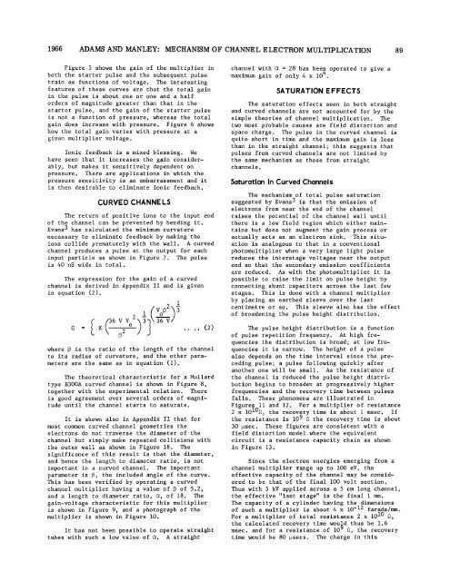
Figure 5 shows <strong>the</strong> gain <strong>of</strong> <strong>the</strong> multiplier in<br />
both <strong>the</strong> starter pulse and <strong>the</strong> subsequent pulse<br />
train as functions <strong>of</strong> voltage. The interesting<br />
features <strong>of</strong> <strong>the</strong>se curves are that <strong>the</strong> total gain<br />
in <strong>the</strong> pulse is about one or one and a half<br />
orders <strong>of</strong> magnitude greater than that in <strong>the</strong><br />
starter pulse, and <strong>the</strong> gain <strong>of</strong> <strong>the</strong> starter pulse<br />
is not a function <strong>of</strong> pressure, whereas <strong>the</strong> total<br />
gain does increase with pressure. Figure 6 shows<br />
how <strong>the</strong> total gain varies with pressure at a<br />
given multiplier voltage.<br />
Ionic feedback is a mixed blessing. We<br />
have seen that it increases <strong>the</strong> gain considerably,<br />
but makes it sensitively dependent on<br />
pressure. There are applications in which <strong>the</strong><br />
pressure sensitivity is an embarrassment and it<br />
is <strong>the</strong>n desirable to eliminate ionic feedback.<br />
CURVED CHANNELS<br />
The return <strong>of</strong> positive ions to <strong>the</strong> input end<br />
<strong>of</strong> <strong>the</strong> <strong>channel</strong> can be prevented by bending it.<br />
Evans3 has calculated <strong>the</strong> minimum curvature<br />
necessary to eliminate feedback by making <strong>the</strong><br />
ions collide prematurely with <strong>the</strong> wall. A curved<br />
<strong>channel</strong> produces a pulse at <strong>the</strong> output for each<br />
input particle as shown in Figure 7. The pulse<br />
is 40 nS wide in total.<br />
The expression for <strong>the</strong> gain <strong>of</strong> a curved<br />
<strong>channel</strong> is derived in Appendix II and is given<br />
in equation (2).<br />
( 21<br />
3<br />
1 V=<br />
36_V V 2\3 36V/<br />
G<br />
=<br />
K .. .. (2)<br />
where f is <strong>the</strong> ratio <strong>of</strong> <strong>the</strong> length <strong>of</strong> <strong>the</strong> <strong>channel</strong><br />
to its radius <strong>of</strong> curvature, and <strong>the</strong> o<strong>the</strong>r parameters<br />
are <strong>the</strong> same as in equation (1).<br />
The <strong>the</strong>oretical characteristic for a Mullard<br />
type B300A curved <strong>channel</strong> is shown in Figure 8,<br />
toge<strong>the</strong>r with <strong>the</strong> experimental relation. There<br />
is good agreement over several orders <strong>of</strong> magnitude<br />
until <strong>the</strong> <strong>channel</strong> starts to saturate.<br />
It is shown also in Appendix II that for<br />
most common curved <strong>channel</strong> geometries <strong>the</strong><br />
<strong>electron</strong>s do not traverse <strong>the</strong> diameter <strong>of</strong> <strong>the</strong><br />
<strong>channel</strong> but simply make repeated collisions with<br />
<strong>the</strong> outer wall as shown in Figure 18. The<br />
significance <strong>of</strong> this result is that <strong>the</strong> diameter,<br />
and hence <strong>the</strong> length to diameter ratio, is not<br />
important in a curved <strong>channel</strong>. The important<br />
parameter is 3, <strong>the</strong> included angle <strong>of</strong> <strong>the</strong> curve.<br />
This has been verified by operating a curved<br />
<strong>channel</strong> multiplier having a value <strong>of</strong> 3 <strong>of</strong> 5.2,<br />
and a length to diameter ratio, Ot, <strong>of</strong> 18. The<br />
gain-voltage characteristic for this multiplier<br />
is shown in Figure 9, and a photograph <strong>of</strong> <strong>the</strong><br />
multiplier is shown in Figure 10.<br />
It has not been possible to operate straight<br />
tubes with such a low value <strong>of</strong> a. A straight<br />
<strong>channel</strong> with Ca = 28 has bees operated to give a<br />
maximum gain <strong>of</strong> only 4 x 10 .<br />
SATURATION EFFECTS<br />
The saturation effects seen in both straight<br />
and curved <strong>channel</strong>s are not accounted for by <strong>the</strong><br />
simple <strong>the</strong>ories <strong>of</strong> <strong>channel</strong> <strong>multiplication</strong>. The<br />
two most probable causes are field distortion and<br />
space charge. The pulse in <strong>the</strong> curved <strong>channel</strong> is<br />
quite short in time and <strong>the</strong> maximum gain is less<br />
than in <strong>the</strong> straight <strong>channel</strong>; this suggests that<br />
pulses from curved <strong>channel</strong>s are not limited by<br />
<strong>the</strong> same <strong>mechanism</strong> as those from straight<br />
<strong>channel</strong>s.<br />
Saturation in Curved Channels<br />
The <strong>mechanism</strong> <strong>of</strong> total pulse saturation<br />
suggested by Evans3 is that <strong>the</strong> emission <strong>of</strong><br />
<strong>electron</strong>s from near <strong>the</strong> end <strong>of</strong> <strong>the</strong> <strong>channel</strong><br />
raises <strong>the</strong> potential <strong>of</strong> <strong>the</strong> <strong>channel</strong> wall until<br />
<strong>the</strong>re is a low field region which ei<strong>the</strong>r maintains<br />
but does not augment <strong>the</strong> gain process or<br />
actually acts as an <strong>electron</strong> sink. This situation<br />
is analogous to that in a conventional<br />
photomultiplier when a very large light pulse<br />
reduces <strong>the</strong> interstage voltages near <strong>the</strong> output<br />
end so that <strong>the</strong> secondary emission coefficients<br />
are reduced. As with <strong>the</strong> photomultiplier it is<br />
possible to raise <strong>the</strong> limit on pulse height by<br />
connecting shunt capacitors across <strong>the</strong> last few<br />
stages. This is done with a <strong>channel</strong> multiplier<br />
by placing an ear<strong>the</strong>d sleeve over <strong>the</strong> last<br />
centimetre or so. This sleeve also has <strong>the</strong> effect<br />
<strong>of</strong> broadening <strong>the</strong> pulse height distribution.<br />
The pulse height distribution is a function<br />
<strong>of</strong> pulse repetition frequency. At high frequencies<br />
<strong>the</strong> distribution is broad; at low frequencies<br />
it is narrow. The height <strong>of</strong> a pulse<br />
also depends on <strong>the</strong> time interval since <strong>the</strong> preceding<br />
pulse; a pulse following quickly after<br />
ano<strong>the</strong>r one will be small. As <strong>the</strong> resistance <strong>of</strong><br />
<strong>the</strong> <strong>channel</strong> is reduced <strong>the</strong> pulse height distribution<br />
begins to broaden at progressively higher<br />
frequencies and <strong>the</strong> recovery time between pulses<br />
falls. These phenomena are illustrated in<br />
Figures 11 and 12. For a multiplier <strong>of</strong> resistance<br />
2 x 101%, <strong>the</strong> recovery time is about 1 msec. If<br />
<strong>the</strong> resistance is 109 Q <strong>the</strong> recovery time is about<br />
30 ptsec. These figures are consistent with a<br />
field distortion model where <strong>the</strong> equivalent<br />
circuit is a resistance capacity chain as shown<br />
in Figure 13.<br />
Since <strong>the</strong> <strong>electron</strong> energies emerging from a<br />
<strong>channel</strong> multiplier range up to 100 eV, <strong>the</strong><br />
effective capacity <strong>of</strong> <strong>the</strong> <strong>channel</strong> may be considered<br />
to be that <strong>of</strong> <strong>the</strong> final 100 volt section.<br />
Thus with 5 kV applied across a 5 cm long <strong>channel</strong>,<br />
<strong>the</strong> effective "last stage" is <strong>the</strong> final 1 mm.<br />
The capacity <strong>of</strong> a cylinder having <strong>the</strong> dimensions<br />
<strong>of</strong> such a multiplier is about 4 x 10-12 farads/mm.<br />
For a multiplier <strong>of</strong> total resistance 2 x 10¹⁰ Q,<br />
<strong>the</strong> calculated recovery time would thus be 1.6<br />
msec. and for a resistance <strong>of</strong> 109 Q, <strong>the</strong> recovery<br />
time would be 80 [isecs. The charge in this