the mechanism of channel electron multiplication - IEEE Xplore
the mechanism of channel electron multiplication - IEEE Xplore
the mechanism of channel electron multiplication - IEEE Xplore

Create successful ePaper yourself
Turn your PDF publications into a flip-book with our unique Google optimized e-Paper software.
88 <strong>IEEE</strong> TRANSACTIONS ON NUCLEAR SCIENCE<br />
June<br />
THE MECHANISM OF CHANNEL ELECTRON MULTIPLICATION<br />
SUMMARY<br />
The paper attempts to relate <strong>the</strong> important<br />
parameters observed in <strong>channel</strong>led <strong>electron</strong> <strong>multiplication</strong><br />
to <strong>the</strong> physical processes involved.<br />
Ionic feedback and <strong>the</strong> effect <strong>of</strong> <strong>channel</strong> geometry<br />
on it are discussed. Saturation effects occurring<br />
in straight <strong>channel</strong>s and curved <strong>channel</strong>s are<br />
described and <strong>the</strong> different pulse height distributions<br />
are contrasted.<br />
INTRODUCTION<br />
The <strong>channel</strong> <strong>electron</strong> multiplier is now a<br />
well known instrumentl2 which needs only a brief<br />
description before we discuss its operation in<br />
detail.<br />
A <strong>channel</strong> multiplier is shown in Figure 1.<br />
It is a tube <strong>of</strong> suitably resistive material, with<br />
a length which is large compared to its diameter.<br />
Between <strong>the</strong> ends <strong>of</strong> <strong>the</strong> multiplying <strong>channel</strong> a<br />
potential <strong>of</strong> a few thousand volts is applied in<br />
vacuum. Electrons or o<strong>the</strong>r energetic particles<br />
striking <strong>the</strong> low voltage end <strong>of</strong> <strong>the</strong> <strong>channel</strong><br />
release secondary <strong>electron</strong>s with some initial<br />
energy which carries <strong>the</strong>m across <strong>the</strong> <strong>channel</strong>.<br />
While <strong>the</strong>y traverse <strong>the</strong> <strong>channel</strong> <strong>the</strong> applied<br />
electric field accelerates <strong>the</strong> <strong>electron</strong>s axially<br />
until <strong>the</strong>y collide with <strong>the</strong> wall with sufficient<br />
energy to release more secondaries. This process<br />
is repeated many times so that a very large<br />
number <strong>of</strong> <strong>electron</strong>s emerge from <strong>the</strong> output end.<br />
The pulse initiated by a single <strong>electron</strong> may in<br />
certain circumstances contain more than 109<br />
<strong>electron</strong>s. The gain obtainable from a <strong>channel</strong> is<br />
a function <strong>of</strong> a number <strong>of</strong> parameters: <strong>the</strong> applied<br />
voltage, residual gas pressure, <strong>the</strong> resistance<br />
and geometry <strong>of</strong> <strong>the</strong> tube, and pulse repetition<br />
rate.<br />
A <strong>channel</strong> multiplier amplifies direct<br />
currents and also counts energetic particles by<br />
producing corresponding pulses. This paper is<br />
devoted to pulsed operation.<br />
THE GAIN-VOLTAGE CHARACTERISTIC<br />
We can see intuitively that <strong>the</strong> energy <strong>of</strong><br />
collision <strong>of</strong> secondary <strong>electron</strong>s with <strong>the</strong> <strong>channel</strong><br />
wall will increase with <strong>the</strong> applied voltage but<br />
at <strong>the</strong> same time <strong>the</strong> number <strong>of</strong> collisions will<br />
decrease. We thus expect that <strong>the</strong> gain will rise<br />
to a maximum value and <strong>the</strong>n decrease as <strong>the</strong><br />
voltage is increased fur<strong>the</strong>r. An expression<br />
showing <strong>the</strong> dependence <strong>of</strong> gain on <strong>the</strong> applied<br />
voltage is derived in Appendix I and is given in<br />
equation (1).<br />
J. Adams and B.W. Manley<br />
Mullard Research Laboratories,<br />
Redhill, Surrey, England<br />
KV 2<br />
=<br />
G )<br />
4Va2<br />
where G is <strong>the</strong> gain<br />
VO is <strong>the</strong> applied voltage<br />
V is <strong>the</strong> initial energy <strong>of</strong> <strong>the</strong><br />
secondary <strong>electron</strong><br />
cx is <strong>the</strong> ratio <strong>of</strong> length to diameter<br />
K is a constant from <strong>the</strong> relation<br />
= KVc where<br />
is <strong>the</strong> secondary emission coefficient<br />
and Vc is <strong>the</strong> collision energy<br />
VO<br />
.... ... (1)<br />
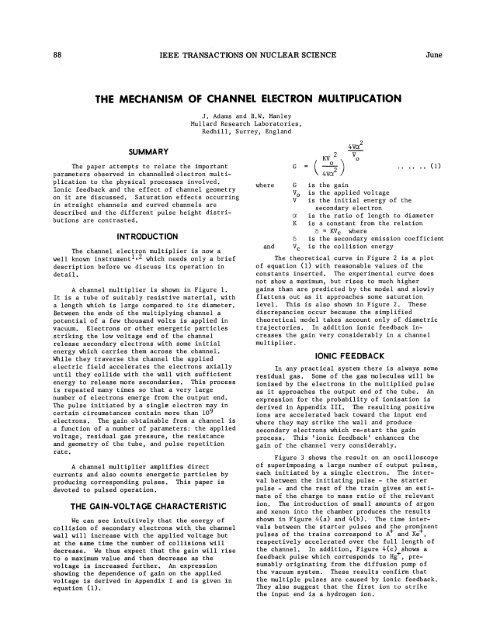
The <strong>the</strong>oretical curve in Figure 2 is a plot<br />
<strong>of</strong> equation (1) with reasonable values <strong>of</strong> <strong>the</strong><br />
constants inserted. The experimental curve does<br />
not show a maximum, but rises to much higher<br />
gains than are predicted by <strong>the</strong> model and slowly<br />
flattens out as it approaches some saturation<br />
level. This is also shown in Figure 2. These<br />
discrepancies occur because <strong>the</strong> simplified<br />
<strong>the</strong>oretical model takes account only <strong>of</strong> diametric<br />
trajectories. In addition ionic feedback increases<br />
<strong>the</strong> gain very considerably in a <strong>channel</strong><br />
multiplier.<br />
IONIC FEEDBACK<br />
In any practical system <strong>the</strong>re is always some<br />
residual gas. Some <strong>of</strong> <strong>the</strong> gas molecules will be<br />
ionised by <strong>the</strong> <strong>electron</strong>s in <strong>the</strong> multiplied pulse<br />
as it approaches <strong>the</strong> output end <strong>of</strong> <strong>the</strong> tube. An<br />
expression for <strong>the</strong> probability <strong>of</strong> ionisation is<br />
derived in Appendix III. The resulting positive<br />
ions are accelerated back toward <strong>the</strong> input end<br />
where <strong>the</strong>y may strike <strong>the</strong> wall and produce<br />
secondary <strong>electron</strong>s which re-start <strong>the</strong> gain<br />
process. This 'ionic feedback' enhances <strong>the</strong><br />
gain <strong>of</strong> <strong>the</strong> <strong>channel</strong> very considerably.<br />
Figure 3 shows <strong>the</strong> result on an oscilloscope<br />
<strong>of</strong> superimposing a large number <strong>of</strong> output pulses,<br />
each initiated by a single <strong>electron</strong>. The interval<br />
between <strong>the</strong> initiating pulse - <strong>the</strong> starter<br />
pulse<br />
-<br />
and<br />
<strong>the</strong> rest <strong>of</strong> <strong>the</strong> train gives an estimate<br />
<strong>of</strong> <strong>the</strong> charge to mass ratio <strong>of</strong> <strong>the</strong> relevant<br />
ion. The introduction <strong>of</strong> small amounts <strong>of</strong> argon<br />
and xenon into <strong>the</strong> chamber produces <strong>the</strong> results<br />
shown in Figure 4(a) and 4(b). The time intervals<br />
between <strong>the</strong> starter pulses and <strong>the</strong> prominent<br />
pulses <strong>of</strong> <strong>the</strong> trains correspond to A+ and Xe+,<br />
respectively accelerated over <strong>the</strong> full length <strong>of</strong><br />
<strong>the</strong> <strong>channel</strong>. In addition, Figure 4(c)+shows a<br />
feedback pulse which corresponds to Hg , presumably<br />
originating from <strong>the</strong> diffusion pump <strong>of</strong><br />
<strong>the</strong> vacuum system. These results confirm that<br />
<strong>the</strong> multiple pulses are caused by ionic feedback.<br />
They also suggest that <strong>the</strong> first ion to strike<br />
<strong>the</strong> input end is a hydrogen ion.
1966 ADAMS AND MANLEY: MECHANISM OF CHANNEL ELECTRON MULTIPLICATION 89<br />
Figure 5 shows <strong>the</strong> gain <strong>of</strong> <strong>the</strong> multiplier in<br />
both <strong>the</strong> starter pulse and <strong>the</strong> subsequent pulse<br />
train as functions <strong>of</strong> voltage. The interesting<br />
features <strong>of</strong> <strong>the</strong>se curves are that <strong>the</strong> total gain<br />
in <strong>the</strong> pulse is about one or one and a half<br />
orders <strong>of</strong> magnitude greater than that in <strong>the</strong><br />
starter pulse, and <strong>the</strong> gain <strong>of</strong> <strong>the</strong> starter pulse<br />
is not a function <strong>of</strong> pressure, whereas <strong>the</strong> total<br />
gain does increase with pressure. Figure 6 shows<br />
how <strong>the</strong> total gain varies with pressure at a<br />
given multiplier voltage.<br />
Ionic feedback is a mixed blessing. We<br />
have seen that it increases <strong>the</strong> gain considerably,<br />
but makes it sensitively dependent on<br />
pressure. There are applications in which <strong>the</strong><br />
pressure sensitivity is an embarrassment and it<br />
is <strong>the</strong>n desirable to eliminate ionic feedback.<br />
CURVED CHANNELS<br />
The return <strong>of</strong> positive ions to <strong>the</strong> input end<br />
<strong>of</strong> <strong>the</strong> <strong>channel</strong> can be prevented by bending it.<br />
Evans3 has calculated <strong>the</strong> minimum curvature<br />
necessary to eliminate feedback by making <strong>the</strong><br />
ions collide prematurely with <strong>the</strong> wall. A curved<br />
<strong>channel</strong> produces a pulse at <strong>the</strong> output for each<br />
input particle as shown in Figure 7. The pulse<br />
is 40 nS wide in total.<br />
The expression for <strong>the</strong> gain <strong>of</strong> a curved<br />
<strong>channel</strong> is derived in Appendix II and is given<br />
in equation (2).<br />
( 21<br />
3<br />
1 V=<br />
36_V V 2\3 36V/<br />
G<br />
=<br />
K .. .. (2)<br />
where f is <strong>the</strong> ratio <strong>of</strong> <strong>the</strong> length <strong>of</strong> <strong>the</strong> <strong>channel</strong><br />
to its radius <strong>of</strong> curvature, and <strong>the</strong> o<strong>the</strong>r parameters<br />
are <strong>the</strong> same as in equation (1).<br />
The <strong>the</strong>oretical characteristic for a Mullard<br />
type B300A curved <strong>channel</strong> is shown in Figure 8,<br />
toge<strong>the</strong>r with <strong>the</strong> experimental relation. There<br />
is good agreement over several orders <strong>of</strong> magnitude<br />
until <strong>the</strong> <strong>channel</strong> starts to saturate.<br />
It is shown also in Appendix II that for<br />
most common curved <strong>channel</strong> geometries <strong>the</strong><br />
<strong>electron</strong>s do not traverse <strong>the</strong> diameter <strong>of</strong> <strong>the</strong><br />
<strong>channel</strong> but simply make repeated collisions with<br />
<strong>the</strong> outer wall as shown in Figure 18. The<br />
significance <strong>of</strong> this result is that <strong>the</strong> diameter,<br />
and hence <strong>the</strong> length to diameter ratio, is not<br />
important in a curved <strong>channel</strong>. The important<br />
parameter is 3, <strong>the</strong> included angle <strong>of</strong> <strong>the</strong> curve.<br />
This has been verified by operating a curved<br />
<strong>channel</strong> multiplier having a value <strong>of</strong> 3 <strong>of</strong> 5.2,<br />
and a length to diameter ratio, Ot, <strong>of</strong> 18. The<br />
gain-voltage characteristic for this multiplier<br />
is shown in Figure 9, and a photograph <strong>of</strong> <strong>the</strong><br />
multiplier is shown in Figure 10.<br />
It has not been possible to operate straight<br />
tubes with such a low value <strong>of</strong> a. A straight<br />
<strong>channel</strong> with Ca = 28 has bees operated to give a<br />
maximum gain <strong>of</strong> only 4 x 10 .<br />
SATURATION EFFECTS<br />
The saturation effects seen in both straight<br />
and curved <strong>channel</strong>s are not accounted for by <strong>the</strong><br />
simple <strong>the</strong>ories <strong>of</strong> <strong>channel</strong> <strong>multiplication</strong>. The<br />
two most probable causes are field distortion and<br />
space charge. The pulse in <strong>the</strong> curved <strong>channel</strong> is<br />
quite short in time and <strong>the</strong> maximum gain is less<br />
than in <strong>the</strong> straight <strong>channel</strong>; this suggests that<br />
pulses from curved <strong>channel</strong>s are not limited by<br />
<strong>the</strong> same <strong>mechanism</strong> as those from straight<br />
<strong>channel</strong>s.<br />
Saturation in Curved Channels<br />
The <strong>mechanism</strong> <strong>of</strong> total pulse saturation<br />
suggested by Evans3 is that <strong>the</strong> emission <strong>of</strong><br />
<strong>electron</strong>s from near <strong>the</strong> end <strong>of</strong> <strong>the</strong> <strong>channel</strong><br />
raises <strong>the</strong> potential <strong>of</strong> <strong>the</strong> <strong>channel</strong> wall until<br />
<strong>the</strong>re is a low field region which ei<strong>the</strong>r maintains<br />
but does not augment <strong>the</strong> gain process or<br />
actually acts as an <strong>electron</strong> sink. This situation<br />
is analogous to that in a conventional<br />
photomultiplier when a very large light pulse<br />
reduces <strong>the</strong> interstage voltages near <strong>the</strong> output<br />
end so that <strong>the</strong> secondary emission coefficients<br />
are reduced. As with <strong>the</strong> photomultiplier it is<br />
possible to raise <strong>the</strong> limit on pulse height by<br />
connecting shunt capacitors across <strong>the</strong> last few<br />
stages. This is done with a <strong>channel</strong> multiplier<br />
by placing an ear<strong>the</strong>d sleeve over <strong>the</strong> last<br />
centimetre or so. This sleeve also has <strong>the</strong> effect<br />
<strong>of</strong> broadening <strong>the</strong> pulse height distribution.<br />
The pulse height distribution is a function<br />
<strong>of</strong> pulse repetition frequency. At high frequencies<br />
<strong>the</strong> distribution is broad; at low frequencies<br />
it is narrow. The height <strong>of</strong> a pulse<br />
also depends on <strong>the</strong> time interval since <strong>the</strong> preceding<br />
pulse; a pulse following quickly after<br />
ano<strong>the</strong>r one will be small. As <strong>the</strong> resistance <strong>of</strong><br />
<strong>the</strong> <strong>channel</strong> is reduced <strong>the</strong> pulse height distribution<br />
begins to broaden at progressively higher<br />
frequencies and <strong>the</strong> recovery time between pulses<br />
falls. These phenomena are illustrated in<br />
Figures 11 and 12. For a multiplier <strong>of</strong> resistance<br />
2 x 101%, <strong>the</strong> recovery time is about 1 msec. If<br />
<strong>the</strong> resistance is 109 Q <strong>the</strong> recovery time is about<br />
30 ptsec. These figures are consistent with a<br />
field distortion model where <strong>the</strong> equivalent<br />
circuit is a resistance capacity chain as shown<br />
in Figure 13.<br />
Since <strong>the</strong> <strong>electron</strong> energies emerging from a<br />
<strong>channel</strong> multiplier range up to 100 eV, <strong>the</strong><br />
effective capacity <strong>of</strong> <strong>the</strong> <strong>channel</strong> may be considered<br />
to be that <strong>of</strong> <strong>the</strong> final 100 volt section.<br />
Thus with 5 kV applied across a 5 cm long <strong>channel</strong>,<br />
<strong>the</strong> effective "last stage" is <strong>the</strong> final 1 mm.<br />
The capacity <strong>of</strong> a cylinder having <strong>the</strong> dimensions<br />
<strong>of</strong> such a multiplier is about 4 x 10-12 farads/mm.<br />
For a multiplier <strong>of</strong> total resistance 2 x 10¹⁰ Q,<br />
<strong>the</strong> calculated recovery time would thus be 1.6<br />
msec. and for a resistance <strong>of</strong> 109 Q, <strong>the</strong> recovery<br />
time would be 80 [isecs. The charge in this
90 <strong>IEEE</strong> TRANSACTIONS ON NUCLEAR SCIENCE<br />
June<br />
capacity is 2.5 x 10⁹ <strong>electron</strong>s, compared with<br />
<strong>the</strong> experimentally observed saturated gain <strong>of</strong><br />
about 4 x 10⁹.<br />
Saturation in Straight Channels<br />
There are several pieces <strong>of</strong> evidence to<br />
suggest that <strong>the</strong> saturation <strong>mechanism</strong> in curved<br />
<strong>channel</strong>s is different from that in straight<br />
<strong>channel</strong>s.<br />
(i) Figure 14 shows <strong>the</strong> pulses from a<br />
curved <strong>channel</strong>. At low frequencies <strong>the</strong> heights<br />
vary over quite a wide range in a random fashion.<br />
Unlike <strong>the</strong> pulses in Figure 11, <strong>the</strong>ir height is<br />
not related to <strong>the</strong> time interval between <strong>the</strong>m.<br />
(ii) The maximum gain8in curved <strong>channel</strong>s<br />
ap ears to be about 2 x 10 , compared with 4 x<br />
10 in straight ones.<br />
(iii) Placing a capacitative sleeve round a<br />
curved <strong>channel</strong> has no effect on <strong>the</strong> size <strong>of</strong> <strong>the</strong><br />
maximum pulse.<br />
Thus it seems unlikely that field distortion<br />
is limiting <strong>the</strong> gain <strong>of</strong> curved <strong>channel</strong> multipliers.<br />
Bryant and Johnstone4 have considered <strong>the</strong> effect<br />
<strong>of</strong> space charge in <strong>channel</strong> multipliers. Their<br />
analysis is more applicable to straight multipliers<br />
than to curved ones, but <strong>the</strong> same general<br />
principles apply. The cloud <strong>of</strong> <strong>electron</strong>s in <strong>the</strong><br />
<strong>channel</strong> increases in density until it is sufficient<br />
to drive secondary <strong>electron</strong>s back into <strong>the</strong><br />
<strong>channel</strong> wall without <strong>the</strong>ir acquiring enough<br />
energy from <strong>the</strong> field to produce more secondaries.<br />
A state <strong>of</strong> dynamic equilibrium is reached when<br />
this happens. It follows from Gauss' Law that n,<br />
<strong>the</strong> number <strong>of</strong> <strong>electron</strong>s per cm length uniformly<br />
distributed within a cylinder which will produce<br />
a voltage depression V volts at <strong>the</strong> centre <strong>of</strong> <strong>the</strong><br />
cylinder is given by n = 7 x 10⁶ V <strong>electron</strong>s/cm.<br />
Few <strong>electron</strong>s emerge from <strong>the</strong> <strong>channel</strong> with<br />
energies exceeding 100 eV. We may presume <strong>the</strong>refore<br />
that <strong>the</strong> maximum collision energy in <strong>the</strong><br />
<strong>channel</strong> is also 100 eV. Channels are invariably<br />
vitreous and since for most glasses <strong>the</strong> secondary<br />
emission coefficient is unity at about 50 eV, a<br />
reduction in collision energy by a factor 2 would<br />
inhibit <strong>the</strong> gain process. It can be shown that a<br />
voltage depression <strong>of</strong> about 2.8 times <strong>the</strong> emission<br />
energy is required to achieve this reduction.<br />
This would suggest a maximum charge density <strong>of</strong><br />
about 2 x 10⁷ <strong>electron</strong>s/cm for 1 volt <strong>electron</strong>s.<br />
The output pulse persists for about 4 x 10⁻⁸<br />
seconds, and since <strong>the</strong> mean energy is about 50 eV,<br />
<strong>the</strong> space charge limited gain is about 3 x 10⁸<br />
<strong>electron</strong>s. It should be noted that this is not a<br />
function <strong>of</strong> tube diameter. This result accords<br />
well with experimental findings.<br />
We can summarise by saying that in curved<br />
<strong>channel</strong>s <strong>the</strong> short pulse is limited by space<br />
charge, while in straight <strong>channel</strong>s <strong>the</strong> long pulse<br />
train is limited by changes <strong>of</strong> <strong>the</strong> potential <strong>of</strong><br />
<strong>the</strong> <strong>channel</strong> wall.<br />
PULSE HEIGHT DISTRIBUTION<br />
We have already alluded to <strong>the</strong> pulse height<br />
distributions in straight and curved <strong>channel</strong>s.<br />
We can now consolidate <strong>the</strong> discussion <strong>of</strong> <strong>the</strong>se<br />
phenomena.<br />
In straight <strong>channel</strong>s <strong>the</strong> pulse height<br />
distribution at maximum gain is very narrow at<br />
low pulse repetition rates. Figure 15 shows <strong>the</strong><br />
contrast between <strong>the</strong> spread in height <strong>of</strong> <strong>the</strong><br />
starter pulses which did not initiate feedback<br />
and <strong>of</strong> <strong>the</strong> larger saturating pulses. It shows<br />
that as <strong>the</strong> multiplying voltage and <strong>the</strong>refore<br />
<strong>the</strong> gain is increased <strong>the</strong> proportion <strong>of</strong> starter<br />
pulses giving rise to feedback also increases.<br />
As <strong>the</strong> pulse repetition rate rises, <strong>the</strong><br />
interval between pulses becomes shorter than <strong>the</strong><br />
recovery time <strong>of</strong> <strong>the</strong> multiplier. The height <strong>of</strong><br />
a pulse <strong>the</strong>refore becomes a function <strong>of</strong> <strong>the</strong> time<br />
interval since <strong>the</strong> preceding one, and <strong>the</strong> pulse<br />
height distribution broadens.<br />
In a curved <strong>channel</strong> <strong>the</strong> maximum pulse<br />
height is limited by space charge and this shows<br />
itself in <strong>the</strong> pulse height distribution. Figure<br />
16 shows distributions obtained from a Mullard<br />
B300A multiplier at various applied voltages.<br />
The resolution <strong>of</strong> a distribution is defined as<br />
<strong>the</strong> ratio <strong>of</strong> <strong>the</strong> full width <strong>of</strong> <strong>the</strong> distribution<br />
at half peak height to <strong>the</strong> gain at <strong>the</strong> peak<br />
height. The resolution improves with gain in<br />
<strong>the</strong> range 105 to 107 but <strong>the</strong>n worsens at about<br />
108. The best resolution is about 0.45, which<br />
is to be compared with about 1.5 obtained in<br />
conventional multidynode multipliers. The<br />
resolution in a conventional multiplier is<br />
limited by <strong>the</strong> statistical variation <strong>of</strong> <strong>the</strong><br />
gain at each stage. According to Lombard and<br />
Martin5, a resolution <strong>of</strong> 1.5 implies a gain per<br />
stage <strong>of</strong> 5, whereas a resolution <strong>of</strong> 0.45 would<br />
require a gain per stage <strong>of</strong> 25. Fur<strong>the</strong>rmore <strong>the</strong><br />
variation <strong>of</strong> gain at each collision in a <strong>channel</strong><br />
will be greater than that in a conventional<br />
multiplier, so an even higher mean gain would be<br />
required to account for <strong>the</strong> resolution <strong>of</strong> <strong>the</strong><br />
<strong>channel</strong>. Because such high gains per stage do<br />
not occur in <strong>channel</strong>s it is evident that <strong>the</strong><br />
narrow distribution cannot be accounted for<br />
statistically, but results from <strong>the</strong> progressive<br />
constraint which space charge imgoses<br />
process when <strong>the</strong> gain exceeds 10 .<br />
on <strong>the</strong> gain<br />
The resolution worsens at gains above 10<br />
and as Figure 16 shows, <strong>the</strong> distribution has a<br />
double peak at 5 KV. This effect is due to<br />
secondary pulses which appear at <strong>the</strong> tail <strong>of</strong> <strong>the</strong><br />
normal curved <strong>channel</strong> output pulse. The probability<br />
<strong>of</strong> occurrence <strong>of</strong> secondary pulses increases<br />
with gain and with <strong>the</strong> length <strong>of</strong> <strong>the</strong> straight<br />
part <strong>of</strong> <strong>the</strong> <strong>channel</strong>.<br />
The cause <strong>of</strong> secondary pulsing <strong>the</strong>refore<br />
seems to be ionic feedback. It is not clear why<br />
<strong>the</strong> number <strong>of</strong> secondary pulses is limited. If<br />
<strong>the</strong> probability <strong>of</strong> feedback is as high as <strong>the</strong><br />
pulse height distribution indicates <strong>the</strong>n <strong>the</strong>re
1966 ADAMS AND MANLEY: MECHANISM OF CHANNEL ELECTRON MULTIPLICATION<br />
91<br />
ought to be some multiple pulses. All types <strong>of</strong><br />
curved multipliers produce secondary pulses to<br />
some extent, and tertiary and quaternary pulses<br />
are also seen, but <strong>the</strong>y are usually very small,<br />
so that <strong>the</strong>y do not make appreciable contributions<br />
to <strong>the</strong> pulse height distribution.<br />
The distribution broadens slightly as <strong>the</strong><br />
repetition frequency increases and <strong>the</strong> relationship<br />
between pulse height and time between pulses<br />
becomes more systematic. This is similar to <strong>the</strong><br />
saturation effect seen in straight <strong>channel</strong>s.<br />
OPERATIONAL CONSIDERATIONS<br />
It is now possible to indicate some operational<br />
characteristics <strong>of</strong> <strong>channel</strong> multipliers.<br />
A <strong>channel</strong> multiplier will detect any radiation<br />
which will excite <strong>electron</strong>s from <strong>the</strong> <strong>channel</strong> wall.<br />
Of course <strong>the</strong> <strong>channel</strong> entrance may be suitably<br />
treated to increase its detection efficiency for<br />
certain types <strong>of</strong> radiation. It is not an energy<br />
sensitive device in <strong>the</strong> sense that a sodium<br />
iodide crystal is for example. The pulses from<br />
<strong>the</strong> multiplier signify only that an input event<br />
has been detected.<br />
It is possible to make straight multipliers<br />
having a sharp pulse height distribution up to<br />
tens <strong>of</strong> kilocycles/sec by using resistive layers<br />
<strong>of</strong> about 109 Q. Straight multipliers have <strong>the</strong><br />
disadvantage that <strong>the</strong> gain depends upon gas<br />
pressure.<br />
Curved multipliers have a broader pulse<br />
height distribution in general, although it is<br />
narrower than that obtained from a conventional<br />
photomultiplier. The highest detectable count<br />
rate is determined by <strong>the</strong> resistance <strong>of</strong> <strong>the</strong><br />
<strong>channel</strong> and by <strong>the</strong> noise level in <strong>the</strong> multiplierpulse<br />
counter system. The choice <strong>of</strong> resistance<br />
is determined by <strong>the</strong> available power and <strong>the</strong> need<br />
for <strong>the</strong> <strong>channel</strong> material to satisfy certain<br />
requirements. It must be stable, for example,<br />
and it should have a reasonably high secondary<br />
emission coefficient. It is necessary to fabricate<br />
<strong>channel</strong>s in a variety <strong>of</strong> shapes and sizes,<br />
<strong>the</strong>refore <strong>the</strong> <strong>channel</strong> material must be easily<br />
worked. Count rates <strong>of</strong> <strong>the</strong> order <strong>of</strong> 105 pulses/<br />
sec above a 5 mV threshold are currently<br />
available.<br />
Gain maintenance is an important characteristic<br />
<strong>of</strong> <strong>channel</strong> multipliers but by <strong>the</strong> nature <strong>of</strong><br />
<strong>the</strong> problem, experimental evidence accumulates<br />
ra<strong>the</strong>r slowly. Deterioration <strong>of</strong> gain does take<br />
place and seems to be due to a combination <strong>of</strong><br />
material changes and surface contamination.<br />
Because <strong>of</strong> changes in <strong>electron</strong> trajectories<br />
in <strong>channel</strong> multipliers it is not possible to<br />
operate <strong>the</strong>m in magnetic fields <strong>of</strong> more than a<br />
few hundred gauss.<br />
CONCLUSION<br />
The <strong>channel</strong> multiplier is a useful research<br />
tool for detecting fluxes <strong>of</strong> energetic particles<br />
and radiation up to 105 output pulses/sec. At<br />
lower count rates it is possible to obtain gains<br />
<strong>of</strong> over 109 in straight <strong>channel</strong>s and 108 in<br />
curved ones. The limitation on gain is probably<br />
space charge in curved <strong>channel</strong>s and field<br />
distortion effects in straight ones.<br />
ACKNOWLE DGME NTS<br />
The authors wish to thank <strong>the</strong> Directors <strong>of</strong><br />
Mullard Ltd. for permission to publish and <strong>the</strong><br />
proprietors <strong>of</strong> "Electronic Engineering" in which<br />
Figures 1 and 7 were previously published. They<br />
are also grateful to Mr. R. Speer <strong>of</strong> <strong>the</strong> Mullard<br />
Space Laboratory, University College, London and<br />
Mr. C. Casemore, <strong>of</strong> Mullard Research Laboratories<br />
for many <strong>of</strong> <strong>the</strong> experimental measurements.<br />
APPENDIX I<br />
Electron Trajectories in Straight Channels<br />
The distance S travelled down <strong>the</strong> tube<br />
between collisions is given by<br />
S = 1E e t<br />
2 m<br />
E is <strong>the</strong> axial electric field.<br />
t is <strong>the</strong> time between collisions.<br />
t = d m<br />
2eV<br />
.... ... (1)<br />
. .... .. (2)<br />
V is <strong>the</strong> initial energy in volts, <strong>of</strong> an <strong>electron</strong><br />
emitted normally from <strong>the</strong> <strong>channel</strong> wall.<br />
d is <strong>the</strong> <strong>channel</strong> diameter.<br />
The collision energy, Vc. is given by<br />
V E S<br />
c<br />
v 2<br />
0<br />
_ o<br />
4 VIa2<br />
where V is <strong>the</strong> total voltage applied to <strong>the</strong><br />
0<br />
<strong>channel</strong>,<br />
and a is <strong>the</strong> length to diameter ratio.<br />
Let <strong>the</strong> secondary emission coefficient 6<br />
obey <strong>the</strong> relation<br />
6 = KV c<br />
K is a constant<br />
The gain G is given by<br />
G = n<br />
cd<br />
where n = S
92 <strong>IEEE</strong> TRANSACTIONS ON NUCLEAR SCIENCE<br />
June<br />
KV 2<br />
24 V aX2<br />
Hence G = 0 0<br />
4Vz2<br />
V<br />
APPENDIX 11<br />
Electron Trajectories in Curved Channels<br />
Consider an <strong>electron</strong> emitted normally from<br />
<strong>the</strong> outer wall <strong>of</strong> <strong>the</strong> <strong>channel</strong> towards <strong>the</strong> centre<br />
<strong>of</strong> curvature <strong>of</strong> <strong>the</strong> <strong>channel</strong>, with an initial<br />
velocity a. We want to find h, <strong>the</strong> height <strong>of</strong> <strong>the</strong><br />
<strong>electron</strong> trajectory and <strong>the</strong> value <strong>of</strong> 6 at which<br />
it strikes ei<strong>the</strong>r wall.<br />
The equations <strong>of</strong> motion are<br />
r e) + 2 r 3= E m<br />
it '2<br />
r = re<br />
.... ... (1)<br />
. . .. .. (2)<br />
where E, <strong>the</strong> electric field is parallel to <strong>the</strong><br />
axis <strong>of</strong> <strong>the</strong> <strong>channel</strong>. In equation (1) r 6 is<br />
always small compared with e and can be neglected.<br />
The tube diameter d is small compared with Ro and<br />
we may assume r is constant and equal to Ro.<br />
Equations (1) and (2) can <strong>the</strong>n be integrated<br />
with <strong>the</strong> initial conditions<br />
r = -a r = R + d<br />
0<br />
e E=o0<br />
<strong>the</strong> resulting expressions are<br />
r =<br />
At3<br />
3R - a<br />
0<br />
where A = E- m<br />
A2t4<br />
and r = R<br />
0<br />
+ d<br />
+12R - at<br />
0<br />
3<br />
From (3) and (4) rmin= R0 + d --at<br />
.. .. .. (3)<br />
.... ... (4)<br />
hence, h <strong>the</strong> max. height <strong>of</strong> <strong>the</strong> <strong>electron</strong> trajectory<br />
is given by<br />
h 81 ~2 V21/<br />
h = R0 16 2<br />
0<br />
..(..<br />
(5)<br />
where V is <strong>the</strong> initial energy <strong>of</strong> <strong>the</strong> <strong>electron</strong><br />
in volts.<br />
VO is <strong>the</strong> applied voltage.<br />
3 is <strong>the</strong> ratio <strong>of</strong> <strong>channel</strong> length to<br />
radius <strong>of</strong> curvature.<br />
(for a full circle 3 = 2XL)<br />
If we write<br />
0R<br />
d =<br />
<strong>the</strong> length to diameter ratio, <strong>the</strong>n from (5) we<br />
can show that h < d if<br />
V.2 3<br />
0 I> 81 a<br />
.(6)<br />
v2 16: ..<br />
This requirement is fulfilled under most<br />
operational conditions.<br />
Since h < d, <strong>the</strong> nest collision will be<br />
with <strong>the</strong> outside wall,<br />
and integrating (1) we find<br />
R @c - .. .. .. (7)<br />
o c 2<br />
where e( is <strong>the</strong> angle between collisions.<br />
From (4) we have<br />
2 12a R 2/3<br />
(\A2<br />
) 1/3<br />
hence R o = R 36-<br />
o c o\ V 0<br />
and <strong>the</strong> energy <strong>of</strong> collision V is given by<br />
VV2 1/3<br />
V = (36 -s.)<br />
c<br />
p<br />
.... ... (8)<br />
.... ... (9)<br />
Let us assume that <strong>the</strong> secondary emission coefficient<br />
6 obeys <strong>the</strong> relation<br />
6 = K V c<br />
The gain G is <strong>the</strong>n given by<br />
G = 6n<br />
where n is <strong>the</strong> number <strong>of</strong> collisions and<br />
hence<br />
G = K (36<br />
c<br />
Wv2 1/3<br />
3v62<br />
\36V<br />
APPENDIX Ill<br />
1/3<br />
Probability <strong>of</strong> lonisation <strong>of</strong> Residual Gas<br />
... . (10)<br />
Consider two planes a distance dL apart in<br />
<strong>the</strong> gap <strong>of</strong> total length L. Electrons are<br />
accelerated and may ionise <strong>the</strong> residual gas.<br />
The number <strong>of</strong> ions found in distance dL is given<br />
by
1966 ADAMS AND MANLEY: MECHANISM OF CHANNEL ELECTRON MULTIPLICATION<br />
93<br />
dN = np f (v) dL<br />
where dN is <strong>the</strong> number <strong>of</strong> ions<br />
n is <strong>the</strong> number <strong>of</strong> <strong>electron</strong>s<br />
p is <strong>the</strong> pressure in torr<br />
f(v) is <strong>the</strong> efficiency <strong>of</strong> ionisation<br />
which is a function <strong>of</strong> V <strong>the</strong><br />
<strong>electron</strong> energy.<br />
If <strong>the</strong> field is uniform<br />
dL<br />
dv<br />
L<br />
V<br />
dN = np v f(v) dV<br />
The total number <strong>of</strong> ions formed as an <strong>electron</strong><br />
accelerates from 0 to V volts in a distance L<br />
is <strong>the</strong>n given by<br />
V<br />
N npL f(v) dV<br />
The function f(v) is given for a number <strong>of</strong> gases<br />
by Meek and Craggs6 and <strong>the</strong> corresponding<br />
function<br />
V<br />
| f(v) dV<br />
0<br />
can be obtained numerically. Since its value<br />
does not vary widely among a number <strong>of</strong> <strong>the</strong> more<br />
comnon gases, one can obtain an estimate <strong>of</strong><br />
f(v) by assuming <strong>the</strong> residual gas is oxygen and<br />
that <strong>the</strong> effective ionisation takes place in <strong>the</strong><br />
last stage <strong>of</strong> <strong>multiplication</strong>. Since <strong>the</strong> energy<br />
<strong>of</strong> <strong>the</strong> emerging <strong>electron</strong>s has a peak <strong>of</strong> about<br />
100 eV, we take V = 100 volts in f(v), and we<br />
find its value is about 6. Hence<br />
N = 6 n p L<br />
As an example, if <strong>the</strong> <strong>channel</strong> is 10 cm long<br />
and <strong>the</strong> applied voltage is 4000 V <strong>the</strong>n L, <strong>the</strong><br />
final stage is 0.25 cm. If n, <strong>the</strong> gain in <strong>the</strong><br />
starter pulse is 106, and <strong>the</strong> pressure is 10-5<br />
torr, <strong>the</strong>n N = 15.<br />
This means that each starter <strong>electron</strong><br />
pulse produces 15 positive ions. If <strong>the</strong> gain is<br />
higher <strong>the</strong>n <strong>of</strong> course more positive ions are<br />
produced.<br />
Figure 15 shows that one third <strong>of</strong> all<br />
starter pulses did not produce ionic feedback<br />
trains under <strong>the</strong> particular experimental<br />
conditions.<br />
The most favourable conditions for feedback<br />
are high gain, high pressure and long <strong>channel</strong>s.<br />
REFERENCES<br />
1. WILEY., W.C. and HENDEE, C.F., I.R.E.<br />
Trans. Nuclear Science, NS-9, 103, (1962)<br />
2. ADAMS, J. and MANLEY, B.W., Electron<br />
Eng. 37, 180, (1965)<br />
3. EVANS, D.S., Rev. Sci. Instr. 36,<br />
375, (1965)<br />
4. BRYANT, D.A. and JOHNSTONE, A.D.,<br />
Rev. Sci. Instr. 36, 1662, (1965)<br />
5. LOMBARD, F.J. and MARTIN, F.,<br />
Rev. Sci. Instr. 32, 200 (1961)<br />
6. MEEK and CRAGGS., "Electrical Breakdown<br />
<strong>of</strong> Gases", 13, (Oxford, Clarendon<br />
Press, 1953)<br />
Fig. 1-Channel Electron Multiplier
94<br />
<strong>IEEE</strong> TRANSACTIONS ON NUCLEAR SCIENCE<br />
June<br />
-_<br />
a<br />
CE a<br />
(0<br />
- b<br />
-~~~~~~~<br />
VO, Multiplying voltage (kilovolts)<br />
Fig. 2-Comparison <strong>of</strong> Theoretical and Experimental<br />
Gain versus voltage characteristics for a<br />
<strong>channel</strong> multiplier<br />
Fig. 4-Ionic feedback pulses produced by (a) argon,<br />
(b) xenon, and (c) mercury. Pressure <strong>of</strong><br />
argon and xenon 4.5 x 10⁻⁵ torr. Pressure<br />
<strong>of</strong> mercury 8 x 10⁻⁴ torr. Scale 0.5 ,u S/large<br />
division. The <strong>channel</strong> used for (a) and @) was<br />
10 cm long, that for (c) 5 cm.<br />
Fig. 3-Ionic feedback pulses from a <strong>channel</strong> multiplier.<br />
Pressure 4 x 10⁻⁶ torr. Scale 0.5<br />
pusec./large division, 0.01 volts/large<br />
division
P<br />
1966 ADAMS AND MANLEY: MECHANISM OF CHANNEL ELECTRON MULTIPLICATION<br />
10'<br />
K -ISO<br />
Sx lOSTorr<br />
'v ln l f/<br />
w -<br />
Total<br />
/ pulse<br />
' 0<br />
/ 5x10 Torr<br />
Starter pulse .5<br />
C,<br />
5xlO Torr<br />
10<br />
In - 4 5<br />
Multiplying voltage (kilovolts)<br />
95<br />
Fig. 5-Gain as a function <strong>of</strong> voltage in starter pulse<br />
and total pulse<br />
Fig. 6-Gain as a function <strong>of</strong> pressure at a given<br />
voltage<br />
Fig. 7-Output pulse from a curved <strong>channel</strong> multiplier<br />
Scale 0.02 uS/Aarge division
96 <strong>IEEE</strong> TRANSACTIONS ON NUCLEAR SCIENCE<br />
June<br />
et Is<br />
A-52<br />
2elCs Torr<br />
10e-<br />
-Theory<br />
K<br />
0<br />
-0-017<br />
o 14 _ 0<br />
V.IVolt 0<br />
0<br />
eo Experiment with<br />
Mullard B300A<br />
(Non standard)<br />
A =14<br />
I<br />
0<br />
.S<br />
13<br />
I<br />
O' _1_<br />
0f '..,<br />
I:_ _I_I<br />
10o<br />
1,<br />
4-0 4.3 i5n0 556( 0<br />
Multiplying voltage (kilovolts)<br />
65 70<br />
Fig. 9-Experimental gain versus voltage curve for<br />
large diameter curved <strong>channel</strong>. Length to<br />
diameter ratio = 18<br />
e<br />
a,.<br />
106 ,<br />
lo'<br />
_~~<br />
I,<br />
le02 ~<br />
I<br />
V0 Multiplying voltage<br />
(iilovolts)<br />
5 0<br />
Fig.<br />
8-Theoretical gain versus voltage characteristic<br />
for Mullard B300A <strong>channel</strong> multiplier. Experimental<br />
points are also shown<br />
Fig. 10-Large diameter curved <strong>channel</strong> multiplier.<br />
Length to diameter ratio = 18. Angle subtended<br />
at centre <strong>of</strong> curvature = 5.2 radians
1966 ADAMS AND MANLEY: MECHANISM OF CHANNEL ELECTRON MULTIPLICATION<br />
97<br />
Notional<br />
~/<br />
Cho<br />
~~~~~~~Beamswitch Electrodes<br />
Fig.<br />
11-Output pulses from straight <strong>channel</strong> illustrating<br />
time dependence <strong>of</strong> pulse height.<br />
Applied voltage 7 kV. Pressure 2 x 10⁻⁵<br />
torr. Gain: about 109. Scale 2 msecs./<br />
large division. 0.1 volts/large division<br />
Fig. 13-Equivalent circuit <strong>of</strong> <strong>channel</strong> multiplier.<br />
The output pulse is obtained when <strong>the</strong> final<br />
capacity is discharged by <strong>the</strong> abeam switch'<br />
|_<br />
~~~~a<br />
Fig. 14-Output pulses from curved <strong>channel</strong> showing<br />
lack <strong>of</strong> dependence <strong>of</strong> height on time. Applied<br />
voltage 7 kV, gain about 108. Scale 100<br />
msecs./large division, 0.2 volts/large<br />
division<br />
2000V<br />
- 2100V<br />
- 2200V<br />
b<br />
GAIN<br />
Fig.<br />
12-Effect <strong>of</strong> <strong>channel</strong> resistance on recovery<br />
time <strong>of</strong> straight <strong>channel</strong> multiplier. (a)<br />
Resistance 7 x 1010.Q. Time scale 50 Msec./<br />
large division. (b) Resistance 109Q. Time<br />
scale 10 p sec./large division<br />
Fig. 15-Pulse height distribution from a straight<br />
<strong>channel</strong> showing distinction between <strong>the</strong><br />
starter pulse and <strong>the</strong> total pulse.
98 <strong>IEEE</strong> TRANSACTIONS ON NUCLEAR SCIENCE<br />
June<br />
1 25Kv<br />
2x 05<br />
2-5Kv<br />
3x10⁷<br />
R~~~~~~1II<br />
1-16mm. OID.x12mm. VD<br />
4Kv<br />
i08 and 2xlO0<br />
5Kv<br />
1.6xlO8and 3-2xl08<br />
1-2<br />
wf-<br />
Jl.^<br />
as I-- lf<br />
.. sX X<br />
It ft i i .%<br />
I a<br />
*<br />
i i ,i<br />
O<br />
L<br />
--W4mm<br />
Mullard B300A<br />
-4 t - i<br />
u<br />
c<br />
0-6 *<br />
w<br />
a<br />
0<br />
c<br />
0<br />
/I I 102 L<br />
/<br />
I /<br />
a I I a I<br />
. A.a<br />
.<br />
- I I I I I I<br />
--<br />
.<br />
.<br />
I IAAA i<br />
Threshold<br />
Peak<br />
Peak<br />
.1<br />
Peak<br />
I I I<br />
Fig. 16-Pulse height distributions from a Mullard B300A curvred chanmel at various applied voltages.<br />
Abscissae logarithmic but not continuous.<br />
10<br />
u<br />
E~~~<br />
_<br />
, 4 /<br />
Ictron<br />
tra<br />
ijectory<br />
d<br />
d<br />
/s- o E<br />
Channel walls\<br />
Fig. 17-Electron trajectory in a straight <strong>channel</strong><br />
Fig. 18-Electron trajectory in a curved <strong>channel</strong>
1966 ADAMS AND MANLEY: MECHANISM OF CHANNEL ELECTRON MULTIPLICATION<br />
99<br />
dL<br />
0 volts V volts<br />
_ L r<br />
Fig. 19-Gas ionisation by accelerated <strong>electron</strong>s