ATmega128 Interrupts
ATmega128 Interrupts
ATmega128 Interrupts

You also want an ePaper? Increase the reach of your titles
YUMPU automatically turns print PDFs into web optimized ePapers that Google loves.
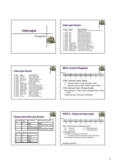
Interrupt Vector<br />
<strong>Interrupts</strong><br />
<strong>ATmega128</strong><br />
No.Addr. Source Interrupt Definition<br />
1 0x0000 RESET External Pin, Power-on Reset, Brown-out Reset, and<br />
Watchdog Reset<br />
2 0x0002 INT0 External Interrupt Request 0<br />
3 0x0004 INT1 External Interrupt Request 1<br />
4 0x0006 INT2 External Interrupt Request 2<br />
5 0x0008 INT3 External Interrupt Request 3<br />
6 0x000A INT4 External Interrupt Request 4<br />
7 0x000C INT5 External Interrupt Request 5<br />
8 0x000E INT6 External Interrupt Request 6<br />
9 0x0010 INT7 External Interrupt Request 7<br />
10 0x0012 TIMER2 COMP Timer/Counter2 Compare Match<br />
11 0x0014 TIMER2 OVF Timer/Counter2 Overflow<br />
12 0x0016 TIMER1 CAPT Timer/Counter1 Capture Event<br />
13 0x0018 TIMER1 COMPA Timer/Counter1 Compare Match A<br />
14 0x001A TIMER1 COMPB Timer/Counter1 Compare Match B<br />
15 0x001C TIMER1 OVF Timer/Counter1 Overflow<br />
16 0x001E TIMER0 COMP Timer/Counter0 Compare Match<br />
Interrupt Vector<br />
No. Addr. Source Interrupt Definition<br />
17 0x0020 TIMER0 OVF Timer/Counter0 Overflow<br />
18 0x0022 SPI, STC Serial Transfer Complete<br />
19 0x0024 USART0, RX USART0, Rx Complete<br />
20 0x0026 USART0, UDRE USART0 Data Register Empty<br />
21 0x0028 USART0, TXC USART0, Tx Complete<br />
22 0x002A ADC ADC Conversion Complete<br />
23 0x002C002C EE READY EEPROM Ready<br />
24 0x002E ANALOG COMP Analog Comparator<br />
25 0x0030 TIMER1 COMPC Timer/Counter1 Compare Match C<br />
26 0x0032 TIMER3 CAPT Timer/Counter3 Capture Event<br />
27 0x0034 TIMER3 COMPA Timer/Counter3 Compare Match A<br />
28 0x0036 TIMER3 COMPB Timer/Counter3 Compare Match B<br />
29 0x0038 TIMER3 COMPC Timer/Counter3 Compare Match C<br />
30 0x003A TIMER3 OVF Timer/Counter3 Overflow<br />
31 0x003C USART1, RX USART1, Rx Complete<br />
32 0x003E USART1, UDRE USART1 Data Register Empty<br />
33 0x0040 USART1, TXC USART1, Tx Complete<br />
34 0x0042 TWI Two-wire Serial Interface<br />
35 0x0044 SPM_RDY Store Program Memory Ready<br />
MCU Control Register<br />
MCUCR<br />
7 6 5 4 3 2 1 0<br />
SRE SRW10 SE SM1 SM0 SM2 IVSEL IVCE<br />
R/W R/W R/W R/W R/W R/W R/W R/W<br />
0 0 0 0 0 0 0 0<br />
IVSEL Interrupt Vector Select<br />
0 … interrupt vector at start of program Flash<br />
1 … interrupt vector at start of Boot Loader section<br />
IVCE Interrupt Vector Change Enable<br />
after setting to 1, IVSEL may be changed within 4 clock<br />
cycles<br />
during that time, interrupts are disabled<br />
Reset and Interrupt Vector<br />
BOOTRST<br />
fuse<br />
IVSEL<br />
MCUCR:1<br />
Reset address<br />
Interrupt Vector address<br />
1 0 $0000 $0002<br />
1 1 $0000 Boot Reset address + $0002<br />
0 0 Boot Reset address $0002<br />
0 1 Boot Reset address Boot Reset address + $0002<br />
BOOTSZ1<br />
fuse<br />
BOOTSZ0<br />
fuse<br />
1 1 $FE00<br />
1 0 $FC00<br />
0 1 $F800<br />
0 0 $F000<br />
Boot Reset address<br />
INT0-3 - External <strong>Interrupts</strong><br />
EICRA<br />
7 6 5 4 3 2 1 0<br />
ISC31 ISC30 ISC21 ISC20 ISC11 ISC10 ISC01 ISC00<br />
R/W R/W R/W R/W R/W R/W R/W R/W<br />
0 0 0 0 0 0 0 0<br />
ISC11-ISC10 Interrupt Sense Control 1<br />
00 … low level 10 … falling edge async<br />
01 … reserved 11 … rising edge async<br />
Level/edge event<br />
asynchronous regardless on the clock<br />
can wake up also from other than just Idle sleep mode<br />
level detected at the end of instruction execution<br />
Multiplex PD0-PD3<br />
1
EICRB<br />
INT4-7 - External <strong>Interrupts</strong><br />
7 6 5 4 3 2 1 0<br />
ISC71 ISC70 ISC61 ISC60 ISC51 ISC50 ISC41 ISC40<br />
R/W R/W R/W R/W R/W R/W R/W R/W<br />
0 0 0 0 0 0 0 0<br />
ISC11-ISC10 Interrupt Sense Control 1<br />
00 … low level 10 … falling edge<br />
01 … any change 11 … rising edge<br />
Level event<br />
asynchronous regardless on the clock<br />
can wake up also from other than just Idle sleep mode<br />
level detected at the end of instruction execution<br />
Edge/toggle event<br />
depends on the clock, pulse must be longer than 1 clock<br />
Multiplex PE4-PE7<br />
EIMSK<br />
External Interrupt Mask Register<br />
7 6 5 4 3 2 1 0<br />
INT7 INT6 INT5 INT4 INT3 INT2 INT1 INT0<br />
R/W R/W R/W R/W R/W R/W R/W R/W<br />
0 0 0 0 0 0 0 0<br />
INT0-7 External Interrupt Request Enable<br />
0 … disabled 1 … enabled<br />
• If the conditions are met, the interrupt is called<br />
even when the pin is set to output<br />
may be used as software interrupt<br />
External Interrupt Flag Register<br />
EIFR<br />
7 6 5 4 3 2 1 0<br />
INTF7 INTF6 INTF5 INTF4 INTF3 INTF2 INTF1 INTF0<br />
R/W R/W R/W R/W R/W R/W R/W R/W<br />
0 0 0 0 0 0 0 0<br />
INT0-7 External Interrupt Flag<br />
0 … clear 1 … interrupt triggered<br />
set when edge/logic change causes INT0-7<br />
jump on the specified location<br />
zeroed after the routine is finished (or manually)<br />
Level interrupt ⇒ always clear<br />
2