
Create successful ePaper yourself
Turn your PDF publications into a flip-book with our unique Google optimized e-Paper software.
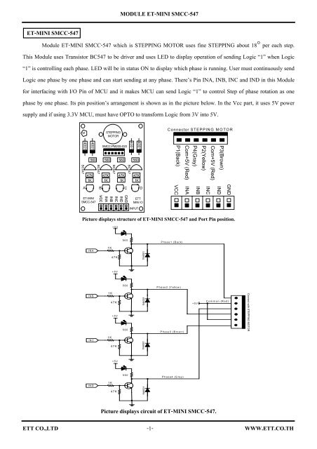
<strong>MODULE</strong> <strong>ET</strong>-<strong>MINI</strong> SEG-A<strong>ET</strong>-<strong>MINI</strong> SEG-AModule <strong>ET</strong>-<strong>MINI</strong> SEG-A which is Common Anode 7-SEGMENT is interfaced with Resistor completely. So,user can interface signal from I/O Pin of MCU with Connector below of MCU and pin position’s arrangement onModule is shown in the picture below. Using this Module, must interface Common Pin with Vdd and must interface a-dp Pin with 8 Pin Port I/o of MCU. If sending Logic “0” to which Segment, that Segment will be in status ON and ifdisplaying number, must decode and decide to send Logic “0” to which Bit. It is easier to decode if user interfaces I/Oof MCU as same as 7-Segment’s pin arrangement.TOS5161B<strong>ET</strong>-<strong>MINI</strong> SEG-A5605605605605605609 110 24<strong>CO</strong>MMON ANODE56056012abcdefg vcc9dp nc 10Picture abovePicture below (not use 10 Pin)Picture displays structure of <strong>ET</strong>-<strong>MINI</strong> SEG-A and Port Pin position.1.a2.b3.c4.d5.e6.f7.g8.dp560 X 8 DPY_7-Seg_DPabcdefgdpfeDPYagdVdd9.VddbcdpgedVddfVdda bc dpPin Position of 7-SegmentPicture displays circuit of <strong>ET</strong>-<strong>MINI</strong> SEG-A.<strong>ET</strong>T <strong>CO</strong>.,<strong>LTD</strong> -1- WWW.<strong>ET</strong>T.<strong>CO</strong>.TH
<strong>MODULE</strong> <strong>ET</strong>-<strong>MINI</strong> SEG-K<strong>ET</strong>-<strong>MINI</strong> SEG-KModule <strong>ET</strong>-<strong>MINI</strong> SEG-K which is Common Cathode 7-SEGMENT is interfaced with Resistor completely. So,user can interface signal from I/O Pin of MCU with Connector below of Module and pin position’s arrangement onModule is shown in the picture below. Using this Module, must interface Common Pin with Ground and interface a-dpPin with 8 Pin Port I/O of MCU. If sending Logic “1” to which Segment, that Segment will be in status ON and ifdisplaying number, must decode and decide to send Logic “1” to which Bit. It is easier to decode if user interfaces I/Oof MCU as same as 7-Segment’s pin arrangement.<strong>ET</strong>-<strong>MINI</strong> SEG-K560560560560910TOS5161APicture above125605605560560<strong>CO</strong>MMON CATHODEa c e g nc192b d f dp gnd 10Picture below (not use 9 Pin)Picture displays structure of <strong>ET</strong>-<strong>MINI</strong> SEG-K and Port Pin position.1.a2.b3.c4.d5.e6.f7.g8.dp560 X 8 DPY_7-Seg_DPabcdefgdpfeDPYagdGNDbcdp10.GNDge dGNDfGNDa bc dpPin position of 7-SegmentPicture displays circuit of <strong>ET</strong>-<strong>MINI</strong> SEG-K.<strong>ET</strong>T <strong>CO</strong>.,<strong>LTD</strong> -1- WWW.<strong>ET</strong>T.<strong>CO</strong>.TH
<strong>MODULE</strong> <strong>ET</strong>-<strong>MINI</strong> 232-TTL2<strong>ET</strong>-<strong>MINI</strong> 232-TTL2Module <strong>ET</strong>-<strong>MINI</strong> 232-TTL2 which is RS232 Communication Line Driver uses 5V power supply. It transforms TTL signal ofMCU into RS232(±12V). There’s 2 channels for using. Firstly, Connector on Input side, must interface Tx PIN and Rx PIN with Tx PINand Rx PIN of MCU respectively. User must interface Tx PIN and Rx PIN in the same channel (Tx0:Rx0, Tx1:Rx1). In the part of +VCCPIN and GND PIN, must interface with power supply of MCU. Secondly, Connector on Output side, uses the same channel as Input sideand then interfaces Rx PIN with Tx PIN and interfaces Tx PIN with Rx PIN of communicate device. Finally, interfaces GND PIN withGND PIN of communicate device but in the part of +VCC, does not interface its.RS232-1RS232-0RS232-1RS232-02TXDGND0.1+VCCRXDMAX232TXDGND+VCCRXDTXD0GNDRXD0+VCC+VCCRXD1TXD1GNDConnector on side of Output CH0 and CH1+ + + ++VCCRX0TX0RX1TX1GNDTTL +5V RS232-LINE DRIVER<strong>ET</strong>-<strong>MINI</strong> 232-TTL2GNDTX1RX1TX0RX0+VCC<strong>ET</strong>TMini IOConnector on Input sidePicture displays structure of <strong>ET</strong>-<strong>MINI</strong> 232-TTL2 and Port PIN position.+VCC=5VRS232-0VCCRXD0TXD0GND++10uF10uF162615131487VCCV+V-GNDR1IT1OR2IT2OC1+C1-C2+C2-1345R1O12T1I11R2O9T2I1010uF10uF++RX0TX0RX1TX1RS232-1VCCRXD1TXD1GNDMAX232Picture displays circuit of <strong>ET</strong>-<strong>MINI</strong> 232-TTL2.<strong>ET</strong>T <strong>CO</strong>.,<strong>LTD</strong> -1- WWW.<strong>ET</strong>T.<strong>CO</strong>.TH
<strong>MODULE</strong> <strong>ET</strong>-<strong>MINI</strong> DS1307<strong>ET</strong>-<strong>MINI</strong> DS1307Module <strong>ET</strong>-<strong>MINI</strong> DS1307 which is Real Time Clock (RTC) I 2 C displays Time Base such as Clock, Timer, andCalendar. There’s SDA Connector and SCL Connecter for interfacing with SDA PIN and SCL PIN of MCUrespectively and for external INT Connector interfaces with MCU when uses Interrupt. It uses VDC 3V-5V powersupply and this I 2 C No. has Control Byte “1101000X”. Moreover, there’s battery box to back UP Time Base correctlywhen Module is not supplied power.Using this Module, firstly, Set Jumper SDA, SCL and INT and place on ENA side as in the picture. It interfacesR Pull Up with all 3 PIN of I 2 C. If interface R Pull Up with 3 PIN of I 2 C. If R Pull Up is interfaced in Line SDA andSCL from external or is interfaced from other Module, must Set Jumper of all 3 PIN and place on DIS side because itdoes not interface R Pull Up once.DIS/ENASDASCLINTSet Jumper when interface with R Pull Up10.1INTDS1307<strong>ET</strong>-<strong>MINI</strong>DS1307DIS/ENASDASCL1101000x10K10K10K32.768KHz+vccSDASCLINT3V GNDBAT 3V+I2C/RTC DS1307<strong>ET</strong>TMini IODIS/ENASDASCLINTSet Jumper when not interface with R Pull UpGNDSDASCLINT+VCCPicture displays structure of <strong>ET</strong>-<strong>MINI</strong> DS1307 and Port PIN position.DIS/ENASDASCLINT+VCC=5V10K x 3VCCSQW/OUTSCLSDA8 7 6 5DS13071 2 3 4X1X2VbatGNDSDASCLINT3V32.768KHzPicture displays circuit of <strong>ET</strong>-<strong>MINI</strong> DS1307.<strong>ET</strong>T <strong>CO</strong>.,<strong>LTD</strong> -1- WWW.<strong>ET</strong>T.<strong>CO</strong>.TH
<strong>MODULE</strong> <strong>ET</strong>-<strong>MINI</strong> PCF8583SDASCLINTSDASCLINTDIS/ENADIS/ENASet Jumper when interface with R Pull UpSet Jumper when not interface with R Pull UpSecondly, it is at RTC/CNT point. It chooses mode operation of I 2 C. In case of using Mode RTC, must SetJumper on RTC side. It interfaces Crystal Pin with OSCI Pin. In case of using Mode Counter, must Set Jumper on CNTside. It interfaces Pin that receives Pulse signal from external and from SW Counter with OSCI Pin of I 2 C as in thepicture below.RTCCNTRTCCNTSet Jumper when using I 2 C to be RTCSet Jumper when using I 2 C to be to be Counter+VCC=3V-5V10K x 3SDASCLINTDIS/ENA1N60x2+-0-30pFVBAT+3V101000[1]xVDDINTSCLSDAOSCI8 7 6 5PCF8583P1 2 3 4OS<strong>CO</strong>A0VSS32.768KHzRTC CNTEXEPULSE10KSDASCLINT+Vcc=3V-5VSW. Counter0.1uPicture displays circuit of <strong>ET</strong>-<strong>MINI</strong> PCF8583.<strong>ET</strong>T <strong>CO</strong>.,<strong>LTD</strong> -2- WWW.<strong>ET</strong>T.<strong>CO</strong>.TH
<strong>MODULE</strong> <strong>ET</strong>-<strong>MINI</strong> 422/485RZRHRLTZTHTLPicture displays Set Jumper to interface R Pull Up because it makes communication a longer distance.RS485TX422TX422RX/4851K0.1TX422RS485TZTHTL1K75176T(+)T(-) R(+)R(-)120TTL +5V RS422/485 LINE DRIVERRLRX4221K0.1RX422RZRH1K751765120RX422T(+) T(-)R(+) R(-)Connector on Output sideGNDRXTXDIR+VCCRS422RS485HALFFULL<strong>ET</strong>-<strong>MINI</strong>422/485+VCCRXTXDIRGND<strong>ET</strong>TMini IOConnector on Input sidePicture displays structure of <strong>ET</strong>-<strong>MINI</strong> 422/485 and Port Pin position.VCC = 5VRS422DIRRS485TXRS485TX422VCC = 5V1R VCC82RE B73DE A64D GND5SN751761K1K120TLTHTZVCCT(+)T(-)RXHALFFULLNC1R2RE3DE4DSN75176RX422VCC8B76A5GNDVCC = 5V1K1KRLRHR(+)R(-)VCC120RZPicture displays circuit of <strong>ET</strong>-<strong>MINI</strong> 422/485.<strong>ET</strong>T <strong>CO</strong>.,<strong>LTD</strong> -2- WWW.<strong>ET</strong>T.<strong>CO</strong>.TH
<strong>MODULE</strong> <strong>ET</strong>-<strong>MINI</strong> 3T05 TTL<strong>ET</strong>-<strong>MINI</strong> 3T05 TTLModule <strong>ET</strong>-<strong>MINI</strong> 3T05 TTL which is OPTO to transform level of Logic from 3V into 5V or from 5 V into 3Vhas 8 channels. It uses with MCU that uses 3.3V power supply to drive or load with 5V power supply. All 8 channels ofthis Module can use as 2 types; only Input or only Output but can not use as both Input/Output in the same time. Itsproceedings are ;1). It is external INPUT for receiving signal Logic 5V into MCU that can receive Logic 3.3V, interface 5Vpower supply with +VIN Connector and Ground with GND of Module respectively and then interface Input [0..7] withconnector for sending signal into MCU. In Output part of Module, interface 3.3V power supply with +VOUT Connectorand Ground with GND of Module respectively and then interface Output [0…7] Connector with I/O Pin of MCU.2). It is OUTPUT for sending signal Logic 3.3V from MCU to control external device that can receive Logic5V, interface 3.3V power supply with +VIN Connector and Ground of MCU with GND of Module respectively andthen interface Input [0..7] with I/O Pin of MCU. In Output part of Module, interface external 5V power supply with+VOUT Connector and external Ground with GND of Module respectively and then interface Output [0…7] Connectorwith controller device.OUT1OUT3OUT5OUT7GND+VOUT0 1 2 3 4 5 6 7OUTPUTGND9OUT0OUT2Connector in side of OUTPUT560560560560560560560560+VININ0IN1IN2IN3IN4IN5IN6IN7GND1K1K1KOUT4OUT6+VOUTPC817PC817PC817PC817PC817PC817PC817PC8171K1K1K+VOUTOUT0OUT1OUT2OUT3OUT4OUT5OUT6OUT7GND1K1K+VIN<strong>ET</strong>-<strong>MINI</strong>3T05 TTL0 1 2 3 4 5 6 7GNDINPUTIN1IN3IN5IN7GNDIN0IN2IN4IN6Connector in size of INPUTPicture displays structure of <strong>ET</strong>-<strong>MINI</strong> 3TO5 TTL and Port PIN position .<strong>ET</strong>T <strong>CO</strong>.,<strong>LTD</strong> -1- WWW.<strong>ET</strong>T.<strong>CO</strong>.TH+VIN
<strong>MODULE</strong> <strong>ET</strong>-<strong>MINI</strong> 3T05 TTL+VIN560 x8 PC8171k x8+VOUTIN0OUT0IN1OUT1IN2OUT2IN3OUT3IN4OUT4IN5OUT5IN6OUT6IN7OUT7Picture displays circuit of <strong>ET</strong>-<strong>MINI</strong> 3TO5 TTL.<strong>ET</strong>T <strong>CO</strong>.,<strong>LTD</strong> -2- WWW.<strong>ET</strong>T.<strong>CO</strong>.TH
User Manual For <strong>ET</strong>-<strong>MINI</strong> AUDIO OUT<strong>ET</strong>-<strong>MINI</strong> AUDIO OUTIt is a mini amplifier with speaker that receives Inputas Analog audio signal type and sends audio signal out throughspeaker. Moreover, there is Stereo Jack that can be interfacedwith headphone or external amplifier.Specifications of Board <strong>ET</strong>-<strong>MINI</strong> AUDIO OUT• Mini Speaker Model PB-2015• Receive signal as Analog Input• Auto-cut audio of speaker PB-2015 on board when StereoJack is inserted.• IC LM386 is designed to be circuit amplifier- 1- www.ett.co.th
User Manual For <strong>ET</strong>-<strong>MINI</strong> LOGIC LEVEL SHIFTER<strong>ET</strong>-<strong>MINI</strong> LOGIC LEVEL SHIFTERThe connection Logic Voltage between 3.3V and 5V<strong>ET</strong>-<strong>MINI</strong> LOGIC LEVEL SHIFTER is a circuit for connectionsignal Logic between +5V device and 3.3V device (or 3V) byusing IC Buffer 74LXX245. Specifications of this IC run withVoltage 3.3V but it can support Voltage Input up to 5V, so wecan use it to be Buffer of Voltage from 3.3V to 5V.Specifications of <strong>ET</strong>-<strong>MINI</strong> LOGIC LEVEL SHIFTER• Can send signal Logic 5V to be signal Logic 3.3V• 8 Channels for connection• Can configure directions of signal• IC Regulator 3.3V/500mA for supplying power into 3.3Vdevice- 1- www.ett.co.th
User Manual For <strong>ET</strong>-<strong>MINI</strong> LOGIC LEVEL SHIFTER**NOTE**Regulator 3.3V/500mA is provided internal circuit, sowe only supply power into Connector 5+5V and Voltage 3.3Vat Connector 3V3 can supply power into external devices.If external device has already had 3.3V power supply, wemust interface GND only and should not interface externalVoltage with +3V3 internal board because circuit maybedamaged.ApplicationsWe can divide it into groups of application as follows;1. Connection as only one direction type from 5V device into3.3V device.We must set Jumper DIR on the position A-TO-B, Logic5V must be interfaced on A side and Logic 3.3V must beinterfaced on B side. Signal Logic 5V on A side is sentthrough Buffer to be Logic 3.3V on B side.- 2- www.ett.co.th
User Manual For <strong>ET</strong>-<strong>MINI</strong> LOGIC LEVEL SHIFTER2. Connection as only one direction type from 3.3V deviceinto 5V device.We must set Jumper DIR on the position B-TO-A, Logic5V must be interfaced on A side and Logic 3.3V must beinterfaced on B side. Signal Logic 3.3V on B side is sentthrough Buffer to be Logic of device on A side. Voltagethat is sent into A device is 3.3V and it is enough for Adevice to know Logic “1” and “0”.+3V3B-TO-ADIRA-TO-BDevice 5V (A)+5V+3V3VCCDin0Din1Din2Din3Din4Din5Din6Din7GND+5VA0A1A2A3A4A5A6A7GND12345678910DIRA0A1A2A3A4A5A6A7GNDVCCEB0B1B2B3B4B5B6B720191817161514131211+3V3+3V3B0B1B2B3B4B5B6B7GNDDevice 3.3V (B)VCCDout0Dout1Dout2Dout3Dout4Dout5Dout6Dout7GND- 3- www.ett.co.th
User Manual For <strong>ET</strong>-<strong>MINI</strong> LOGIC LEVEL SHIFTER3. Connection as bi-direction type between3.3V device and 5V device.From the circuit above, it is the connection signal Logicbetween 5V device and 3V device. We must interface signal PinOutput of A device with signal Pin Input of B device and theninterface signal Pin Output of B device with signal Pin Inputof A device. To configure directions of IC 74LXX245 must n=beconfigured all 8 bit and we can configure in each bit, so ifwe must connect signal of both sender and receptor (both 3.3Vdevice and 5V device), we must configure DIR to be A-TO-B asin the example circuit above.Example: The connection signal between Microcontroller (5Vdevice) and SD/MMC CARD (3V device) by using <strong>ET</strong>-<strong>MINI</strong> SD/MMC inSPI MODE.- 4- www.ett.co.th
User Manual For <strong>ET</strong>-<strong>MINI</strong> LOGIC LEVEL SHIFTERSD/MMCSOCK<strong>ET</strong>74LXX245- 5- www.ett.co.th
User Manual For <strong>ET</strong>-<strong>MINI</strong> SD/MMC<strong>ET</strong>-<strong>MINI</strong> SD/MMCThe connection SD/MMC MEMORY CARD<strong>ET</strong>-<strong>MINI</strong> SD/MMC is a device for connection components withSD/MMC memory Card; for example, the connection betweenMicrocontroller and Memory Card (SD/MMC). This set containsSocket for inserting Memory Card such as SD and MMC and itprovides external signal Pin at Connector Pin, so it is quiteconvenient to apply. Moreover, there are many circuits such asCircuit Card Detect, Circuit Pull-Up and etc.Specifications of <strong>ET</strong>-<strong>MINI</strong> SD/MMC• Support Memory Card as SD type and MMC type• Can select Enable/ Disable for Circuit Pull-Up• Can display status of inserting Card or CARD D<strong>ET</strong>ECT byusing LED and send signal OUTPUT through Pin signal CD.There is specification as follows;CD = 1; It means that there is no Card.CD = 0; It means that there is Card.• Can display status of Switch Write Protection on SD/MMCCard and send signal OUTPUT through signal Pin WP asfollows;WP = 1; It is OFF position of Switch WriteProtection.WR = 0; It is ON position of Switch Write Protection.- 1- www.ett.co.th
User Manual For <strong>ET</strong>-<strong>MINI</strong> SD/MMCExample: The connection signal between Microcontroller (5Vdevice) and SD/MMC CARD (3V device) by using <strong>ET</strong>-<strong>MINI</strong> LOGICLEVEL and <strong>ET</strong>-<strong>MINI</strong> SD/MMC in SPI Mode.- 2- www.ett.co.th
User Manual For <strong>ET</strong>-<strong>MINI</strong> SD/MMCSD/MMCSOCK<strong>ET</strong>74LXX245Details of Signal Pin SD CARDThere are 2 proceedings to connect SD CARD; SD MODE typeand SPI MODE type as the details in the table below.- Details of signal Pin when it is connected as SD MODEtype.- 3- www.ett.co.th
User Manual For <strong>ET</strong>-<strong>MINI</strong> SD/MMC- Details of signal Pin when it is connected as SPI MODEtype.Details of Signal Pin MMC CARDThere are 2 proceedings to connect MMC CARD;MultiMediaCard MODE and SPI MODE as the details in the tablebelow;- Details of signal Pin when it is connected asMultimedia Card Mode type.- Details of signal Pin when it is connected as SPI Modetype.- 4- www.ett.co.th
User Manual For <strong>ET</strong>-<strong>MINI</strong> SD/MMC- 5- www.ett.co.th
User Manual For <strong>ET</strong>-<strong>MINI</strong> MP3<strong>ET</strong>-<strong>MINI</strong> MP3Board <strong>ET</strong>-<strong>MINI</strong> MP3 is a MP3 Decoder to convert signal intovoice. <strong>ET</strong>T uses IC VLSI No.VS1002D to decode file MP3 and tobe the permanent IC on board. VS1002D is the IC MP3 Decoderthat is one of the highest quality and the easiestapplication. It can decode File MP3 and File WAVE instantlyand there is Analog OUTPUT to be Stereo audio type, so we canconnect it with headphone or amplifier instantly.Additionally, we can connect with Microcontroller easily byusing SPI Serial Port standard. So, we can apply <strong>ET</strong>-<strong>MINI</strong> MP3with Microcontrollers as desired.The structural feature of Board <strong>ET</strong>-<strong>MINI</strong> MP3 is just apart of basic circuit VS1002D because it is not applied to beprocessed MP3 Player or connect with any version of BoardMicrocontroller but Board <strong>ET</strong>-<strong>MINI</strong> MP3 can apply with otherproject works independently. Concept of circuit is designedto connect VS1002D with necessary components such as circuitamplifier with Jack Stereo, it is quite convenient to connectwith headphone or amplifier; and circuit Pre-Amplifier toreceive signal from Microphone as Condenser type and includingto circuit Crystal Oscillator Generator. Circuit VS1002D isarranged to be ready to active but there is no signalcontroller only. In the part of signal controller, there isConnector to connect with external microcontroller easily.<strong>ET</strong>T <strong>CO</strong>.,<strong>LTD</strong> -1- WWW.<strong>ET</strong>T.<strong>CO</strong>.TH
Specifications of Board <strong>ET</strong>-<strong>MINI</strong> MP3User Manual For <strong>ET</strong>-<strong>MINI</strong> MP3• IC MP3 Decoder of VLSI No.VS1002D• Be able to decode File MPEG that accesses decoder as MPEG1.0 & 2.0 Audio layer III (CBR + VBR) and including ofWAV and PCM• Be able to access decode audio signal from Microphone tobe standard ADPCM data• Support Streaming Data for File MP3 or WAVE.• Be able adjust Bass Control• Active with signal Clock 12.288 MHz and can use X2 Modeinternal PLL• There is circuit to convert data into high quality of DACvoice with stereo Amplifier. We can connect Audio Outwith amplifier or standard stereo headphone that hasImpedance value about 30Ω instantly. Connector Audio Outof Board uses high quality Jack Stereo that can beinterfaced with headphone or amplifier of computer PCinstantly.• Active with DC Voltage from 2.5V to 3.6V with LED todisplay status of Power and Zener Diode to protect overvoltage• Support connection between signal and Microcontrollerthrough SPI Serial Port• Be able to modify operation of board to be MP3 player asStandalone type without using the any controller fromMicrocontroller (see more information from “ApplicationNote” of VLSI)• Board size 4.4 x 5.6 cm.Applications for Board <strong>ET</strong>-<strong>MINI</strong> MP3We can apply Board <strong>ET</strong>-<strong>MINI</strong> MP3 for many types, especiallythe connection with Microcontroller. We can configurepreferred conditions by self from program controller that isdeveloped. We can apply it by using memories components suchas SD/MMC or others to save File data for sending into VS1002Dto decode and convert into voice. In this case, we do notmention about the memory management and File systems, so usermust study and learn more information by self.The well-known and easiest proceeding to connect Board<strong>ET</strong>-<strong>MINI</strong> MP3 with Microcontroller is connecting with SPI SerialPort. If Microcontroller is active with power supply from+2.5V to +3.3V, we can connect signal between Microcontroller<strong>ET</strong>T <strong>CO</strong>.,<strong>LTD</strong> -2- WWW.<strong>ET</strong>T.<strong>CO</strong>.TH
User Manual For <strong>ET</strong>-<strong>MINI</strong> MP3and IC VS10002D of Board <strong>ET</strong>-<strong>MINI</strong> MP3 instantly; on the otherhand, if Board Microcontroller is active with power supply+5V, we must find circuit to convert Logic +5V into Logic+3.3V first. <strong>ET</strong>T designs Board “<strong>ET</strong>-<strong>MINI</strong> LOGIC LEVEL SHIFTER”to support this application as shown in the diagram below.Figure displays the connection between board <strong>ET</strong>-<strong>MINI</strong> MP3 andMicrocontroller that uses +5V Power Supply.<strong>ET</strong>T <strong>CO</strong>.,<strong>LTD</strong> -3- WWW.<strong>ET</strong>T.<strong>CO</strong>.TH
123410nFD10nF272727LRGAUDIO OUTD10nF+3V3+3V3+3V3CBZENER 3V3XCS#SCLKSIBSYNCRES#SODREQRXTX47uF100K * 2+3V30.1uF+3V310K * 3GPIO0GPIO1GPIO2GPIO3560PWR10uF614194162021222328291333082627+3V3323334910VS1002DDVDD1DVDD2DVDD3DGND1DGND2DGND3DGND4DGND5xCSSCLKSIBSYNC/xDCSxRES<strong>ET</strong>SODREQRXTXTESTGPIO0GPIO1GPIO2/DCLKGPIO3/SDATAXTALIXTALOLEFTRIGHTGBUFMICPMICNAVDD3AVDD2AVDD1RCAPAGND4AGND3AGND2AGND1463942124543384447414037+3V30.1uF1 uF1 uF100pF10 uF1K1K+-1K1K10uFMICROPHONECB100K * 4181M1733pF12.288 MHz33pFATitle<strong>ET</strong>-<strong>MINI</strong> MP3ASize NumberRevisionWWW.<strong>ET</strong>T.<strong>CO</strong>.TH1.0A4Date: 21-Jun-2006 Sheet 1 of 1File: D:\My Circuit\<strong>MINI</strong>-MP3\<strong>MINI</strong>-MP3.Ddb Drawn By: Eakachai Makarn1 2 3 4
An Example Connection <strong>ET</strong>-<strong>MINI</strong> MP3 with MCS51 (<strong>ET</strong>-BASE51 AC3)An Example Connection <strong>ET</strong>-<strong>MINI</strong> MP3 with MCS51This example displays using Port SPI of MCS51No.AT89C51AC3 to connect and command IC VS1002D that is a MP3Decoder. The sample program will mention about proceeding toconnect and command IC VS1002D to play music and voice only.We do not mention about the File systems management, so usermust learn more how to read file data and send it into MP3Decoder to convert into voice by self; for example, theproceeding to use Memory’s types as SD/MMC memory or others.In this case, we use Board Microcontroller MCS51 version<strong>ET</strong>-BASE51 AC3 to control operation of MP3 Decoder and useBoard <strong>ET</strong>-<strong>MINI</strong> MP3. Remember, Board Microcontroller version <strong>ET</strong>-BASE51 AC3 actives with Voltage +5V; on the other hand, <strong>ET</strong>-<strong>MINI</strong> MP3 actives with Voltage +3V3, so IC VS1002D that is aMP3 Decoder in Board <strong>ET</strong>-<strong>MINI</strong> MP3 can not connect with signalLogic TTL with +5V signal level. So, we can not connect signalfrom both boards directly, we must find device to convertsignal +5V into +3V3. In this case, we use <strong>ET</strong>-<strong>MINI</strong> LOGIC LEVELSHIFTER for connection both boards. Additionally, it isnecessary to use these devices as follows;1. Board Microcontroller MCS51 version <strong>ET</strong>-BASE51 AC32. Board <strong>ET</strong>-<strong>MINI</strong> LOGIC LEVEL SHIFTER to convert signalLogic 5V into 3.3V3. Board MP3 Decoder version <strong>ET</strong>-<strong>MINI</strong> MP34. +5V Adapter to supply power into Board <strong>ET</strong>-BASE51 AC3In this case, we use 3 small File Wave that are nothigher than 48 Kbytes totally and we use File Wave Format thatwe can hear it counting number from “0” to “2” in Englishversion to store in Flash memory of AT89C51AC3 as Table type.Next, we must refer to memory position that stores the fileand we must send it to MP3 Decoder to convert into voice asbyte by byte respectively until it is completely. In thisexample, it converts File into data as Byte type and it isarranged as Table type in Flash memory. If it is C Language,it declares variable as Array type and saves it in Flashmemory of CPU because it is more convenient to open file. Thissample is written by C Language and uses Keil-C51 to interpretcommands. Remember, C Language Program (Keil-C51) is used forComplier; if it just Demo Version, it can not interpret SourceCode in this sample program because there is some restrictionfor using Program Keil-C51 Demo version that is not able toComplier Source Code higher than 2KByte. However, <strong>ET</strong>T providesHex File that has already interpreted completely, so user candownload “MCS51_MP3_PLAY_WAVE.HEX” into CPU instantly. Thisfile is saved in Folder named “FINAL_HEX_TEST” to download<strong>ET</strong>T <strong>CO</strong>.,<strong>LTD</strong> -1- WWW.<strong>ET</strong>T.<strong>CO</strong>.TH
An Example Connection <strong>ET</strong>-<strong>MINI</strong> MP3 with MCS51 (<strong>ET</strong>-BASE51 AC3)into CPU of Board <strong>ET</strong>-BASE51 AC3 and can test it instantly. Ifeverything is correct without any error after downloadedcompletely, when we press RES<strong>ET</strong> and connect headphone oramplifier of computer PC with Board <strong>ET</strong>-<strong>MINI</strong> MP3 completely, wewill hear counting number from 0 to 2 in English version andit will be repeated continuously.The connection signal between boards<strong>ET</strong>-BASE51 AC3 Board <strong>ET</strong>-<strong>MINI</strong> LOGIC Board <strong>ET</strong>-<strong>MINI</strong> MP3(MCS51)(DIR = A-TO-B)(VS1002D)[+5V] → [+5V] → [+3V3] → [+3V3][P4.0(Out)] → [A0] → [B0] → [RES#][P4.1(In)] ← [B1] ← [A1] ← [DREQ][P4.2(MISO)] ← [B2] ← [A2] ← [SO][P4.3(SCK)] → [A3] → [B3] → [SCLK][P4.4(MOSI)] → [A4] → [B4] → [SI][P3.4(Out)] → [A5] → [B5] → [XCS#][P3.5(Out)] → [A6] → [B6] → [BSYNC][GND] ↔ [GND] ↔ [GND] ↔ [GND]show the directions and signal to connect MCS51 and <strong>MINI</strong>-MP3<strong>ET</strong>T <strong>CO</strong>.,<strong>LTD</strong> -2- WWW.<strong>ET</strong>T.<strong>CO</strong>.TH
An example Connection <strong>ET</strong>-<strong>MINI</strong> MP3 by AVR (<strong>ET</strong>-BASE AVR ATMEGA64)An example Connection <strong>ET</strong>-<strong>MINI</strong> MP3 by AVRThis example displays using Port SPI of AVR No.ATMEGA64to connect and command IC VS1002D that is a MP3 Decoder. Thesample program will mention about proceeding to connect andcommand IC VS1002D to play music and voice only. We do notmention about the File systems management, so user must learnmore how to read file data and send it into MP3 decoder toconvert into voice by self; for example, the proceeding to useMemory’s types as SD/MMC memory or others.In this case, we use Board Microcontroller AVR version<strong>ET</strong>-BASE AVR ATMEGA64 to control operation of MP3 Decoder anduse Board <strong>ET</strong>-<strong>MINI</strong> MP3. Remember, Board Microcontroller version<strong>ET</strong>-BASE AVR ATMEGA64 runs with Voltage +5V; on the other hand,<strong>ET</strong>-<strong>MINI</strong> MP3 runs with Voltage +3V3, so IC VS1002D that is aMP3 Decoder in Board <strong>ET</strong>-<strong>MINI</strong> MP3 can not connect with signalLogic TTL with +5V signal level. So, we can not connect signalfrom both boards directly, we must find device to convertsignal +5V into +3V3. In this case, we use <strong>ET</strong>-<strong>MINI</strong> LOGIC LEVELSHIFTER for connection both boards. Additionally, it isnecessary to use these devices as follows;1. Board Microcontroller AVR version <strong>ET</strong>-BASE AVR ATMEGA642. Board to convert signal Logic 5V into 3.3V3. Board MP3 Decoder version <strong>ET</strong>-<strong>MINI</strong> MP34. +5V Adapter to supply power into Board <strong>ET</strong>-BASE AVRIn this case, we use 3 small File Wave that are nothigher than 48 Kbytes totally. For this example, we use FileWave Format that we can hear it counting number from “0” to“2” in English version to store in Flash memory of ATMEGA64 asTable type. Next, we must refer to memory position that storesthe file and we must send it to MP3 Decoder to convert intovoice as byte by byte respectively until it is completely. Inthis example, it converts File into data as Byte type and itis arranged as table type in Flash memory. If it is CLanguage, it declares variable as Array type and saves it inFlash memory of CPU because it is more convenient to openfile. This sample is written by C Language and uses CodeVision AVR to interpret commands. Remember, C Language Program(Code Vision AVR) is used for Complier if it just DemoVersion, it can not interpret Source Code in this sampleprogram because there is some restriction for using ProgramCode Vision AVR version Demo that is not able to ComplierSource Code higher than 2KByte. However, <strong>ET</strong>T provides Hex Filethat has already interpreted completely, so user can downloadinto CPU instantly (ATMEGA64_MP3_PLAY_WAVE.HEX). This file is<strong>ET</strong>T <strong>CO</strong>.,<strong>LTD</strong> -1- WWW.<strong>ET</strong>T.<strong>CO</strong>.TH
An example Connection <strong>ET</strong>-<strong>MINI</strong> MP3 by AVR (<strong>ET</strong>-BASE AVR ATMEGA64)saved in Folder named “FINAL_HEX_TEST” to download into CPU ofBoard <strong>ET</strong>-BASE AVR ATMEGA64 and can test it instantly. Ifeverything is correct without any error after downloadedcompletely, when we press RES<strong>ET</strong> and connect headphone oramplifier of computer PC with Board <strong>ET</strong>-<strong>MINI</strong> MP3 completely, wewill hear counting number in English version from 0 to 2 andit will be repeated continuously.The connection signal between boards<strong>ET</strong>-BASE AVR<strong>ET</strong>-<strong>MINI</strong> LOGIC LEVEL<strong>ET</strong>-<strong>MINI</strong> MP3(ATMEGA64)(DIR = A-TO-B)(VS1002D)[+5V] → [+5V] → [+3V3] → [+3V3][PB5(Out)] → [A0] → [B0] → [RES#][PB4(In)] ← [B1] ← [A1] ← [DREQ][PB3(MISO)] ← [B2] ← [A2] ← [SO][PB1(SCK)] → [A3] → [B3] → [SCLK][PB2(MOSI)] → [A4] → [B4] → [SI][PB0(SS#)] → [A5] → [B5] → [XCS#][PB6(Out)] → [A6] → [B6] → [BSYNC][GND] ↔ [GND] ↔ [GND] ↔ [GND]show the directions and signal to connect MEGA64 and <strong>MINI</strong>-MP3<strong>ET</strong>T <strong>CO</strong>.,<strong>LTD</strong> -2- WWW.<strong>ET</strong>T.<strong>CO</strong>.TH
An Example Connection <strong>ET</strong>-<strong>MINI</strong> MP3 by LPC2138/LPC2148An Example Connection <strong>ET</strong>-<strong>MINI</strong> MP3 by ARM7We will mention about an example using Port SPI ofLPC2138/LPC2148 for connection IC VS1002D that is MP3 Decoder. Thesample program will mention about proceeding to connect and commandIC VS1002D to play music and voice only. We do not mention aboutthe File systems management, so user must learn more how to readfile data and send it into MP3 decoder to convert into voice byself; for example, the proceeding to use Memory’s types as SD/MMCmemory or others.For this example, we use 11 small Wave File type and thememory of each file is not higher than 16 KB. We can hear itcounting number from “0” to “10” and is saved in Flash memory ofLPC2138/LPC2148. Next, we must refer to memory position that storesthe file and we must send it to MP3 Decoder to convert into voice.In the first time, we intend to arrange File as Array table typeand include them together in Code program because it is quiteconvenient to open file. Remember, C Language Program (Keil-C51)that is used for Complier is just Demo Version, so there is somerestriction that does not Compiler Source Code is higher than16KByte. Therefore, we should solve this problem by dividing Codeprogram and Audio file first, so each file is not higher than16KByte. After Files are interpreted into HEX completely, we mustcombine Code program and Audio File together. Structure of Memoryspace for saving Code program and code of Audio file are configuredas follows;Memory Position (Code)Application0x00000 - 0x03FFF (16KB) Monitor Code Program0x04000 - 0x07FFF (16KB) Voice “Zero” (0f.wav)0x08000 - 0x0BFFF (16KB) Voice “One” (1f.wav)0x0C000 - 0x0FFFF (16KB) Voice “Two” (2f.wav)0x10000 - 0x13FFF (16KB) Voice “Three” (3f.wav)0x14000 - 0x17FFF (16KB) Voice “Four” (4f.wav)0x18000 - 0x1BFFF (16KB) Voice “Five” (5f.wav)0x1C000 - 0x1FFFF (16KB) Voice “Six” (6f.wav)0x20000 - 0x23FFF (16KB) Voice “Seven” (7f.wav)0x24000 - 0x27FFF (16KB) Voice “Eight” (8f.wav)0x28000 - 0x2BFFF (16KB) Voice “Nine” (9f.wav)0x2C000 - 0x2FFFF (16KB) Voice “Ten” (10f.wav)Table shows the memory management for LPC2138/LPC2148There are many proceedings to convert audio file intoHEX; for example, using program Utility of EPROM programmer toopen audio file as Binary File type and save in the Buffer ofprogram. Next, we must save file that is converted into Hex<strong>ET</strong>T <strong>CO</strong>.,<strong>LTD</strong> -1- WWW.<strong>ET</strong>T.<strong>CO</strong>.TH
An Example Connection <strong>ET</strong>-<strong>MINI</strong> MP3 by LPC2138/LPC2148file completely and we must configure Offset position valuefor storing data as 0x4000 up as shown in the table above. Inthis case, we will mention about using program Utility named“BIN2HEX” that is downloaded from Website of Keil and we candownload this program free without any charge. Program BIN2HEXis a program that runs as Command Line and user can studyUser’s Manual of program from HELP of program. While werunning Program on Dos Prompt, program will display theproceeding. However, we create Batch File named “VOIC.BAT” toconvert audio file into HEX File follow by the positionaddress that is configured as in the table above, so it isquite convenient for user to apply. It is saved in Foldernamed “AudioData” that is overlapped internal Folder of CLanguage Source Code. Details of Batch File are described asfollows;ECHO OFFECHO Generating VOICE.HEX with Wave Files...DEL VOICE.HEXBIN2HEX /L16384 /O16384 /4 /T /Q 0f.wav VOICE.HEXBIN2HEX /L16384 /O32768 /4 /A /T /Q 1f.wav VOICE.HEXBIN2HEX /L16384 /O49152 /4 /A /T /Q 2f.wav VOICE.HEXBIN2HEX /L16384 /O65536 /4 /A /T /Q 3f.wav VOICE.HEXBIN2HEX /L16384 /O81920 /4 /A /T /Q 4f.wav VOICE.HEXBIN2HEX /L16384 /O98304 /4 /A /T /Q 5f.wav VOICE.HEXBIN2HEX /L16384 /O114688 /4 /A /T /Q 6f.wav VOICE.HEXBIN2HEX /L16384 /O131072 /4 /A /T /Q 7f.wav VOICE.HEXBIN2HEX /L16384 /O147456 /4 /A /T /Q 8f.wav VOICE.HEXBIN2HEX /L16384 /O163840 /4 /A /T /Q 9f.wav VOICE.HEXBIN2HEX /L16384 /O180224 /4 /A /Q 10f.wav VOICE.HEXFigure displays commands in Batch File to interpret audio fileinto HEX.When we open Batch File, we will get file named “VOICE.HEX”that is a part of 11 audio files and each file is arranged inmemory as 16KB respectively as shown in the table above.<strong>ET</strong>T <strong>CO</strong>.,<strong>LTD</strong> -2- WWW.<strong>ET</strong>T.<strong>CO</strong>.TH
An Example Connection <strong>ET</strong>-<strong>MINI</strong> MP3 by LPC2138/LPC2148When we get both HEX files; Code Program (it is interpreted byKeil-CARM) and HEX File that is voice that is interpreted by Batchfile (VOICE.BAT). Next step is downloading both Hex files into CPUby using program LPC2000 from Philips. In this case, there are twoproceedings to do as follows;1. Command to download Hex file as file by file. When we open HexFile that is audio file, must select type of delete memory asEnter Device that command to delete all memory and then commandto download audio file first. Next, open HEX File of Source Codebut we must select type of delete memory as Select Sectors typeand must configure position Sector to be 0..3 and then commandto download as in the picture below.↓<strong>ET</strong>T <strong>CO</strong>.,<strong>LTD</strong> -3- WWW.<strong>ET</strong>T.<strong>CO</strong>.TH
An Example Connection <strong>ET</strong>-<strong>MINI</strong> MP3 by LPC2138/LPC21482. Must combine both 2 Hex Files into only one file and thencommand to download only one time as follows;a. Open Hex file of Source Code that is interpreted byKeil-CARM of Program Text Editor such as Notepad. Thencommand to delete the last line that is the end offile Intel HEX (End of HEX Record). The feature of thelast line is shown as in the picture below.:00000001FFb. Open HEX File of audio file that is interpreted byBatch File (VOIC.BAT). Next, copy all data in HEX fileto place at the end of HEX File of Source Code andthen save HEX File of Source Code that is combinedtogether.c. Command to download HEX File that is combined togetherinto board.***NOTE***For HEX File named that is combined together is“LPC2148_MP3_PLAY_WAVE.HEX” and “LPC2138_MP3_PLAY_WAVE.HEX”and is saved in Folder name “FINAL_HEX_TEST. This folder isoverlapped internal Folder of C Language Source Code and HexFile that is in the same Folder of Source Code is Hex File ofSource Code that does not combine with audio file. We can takeHex File in Folder named FINAL_HEX_TEST to download and testinstantly. If everything is correct without any error afterdownloaded completely, when we press RES<strong>ET</strong> and connect withheadphone or amplifier of computer PC, we will hear thecounting number from 0 to 10 in English version and it will berepeated continuously.<strong>ET</strong>T <strong>CO</strong>.,<strong>LTD</strong> -4- WWW.<strong>ET</strong>T.<strong>CO</strong>.TH
An Example Connection <strong>ET</strong>-<strong>MINI</strong> MP3 by LPC2138/LPC2148The connection signal between boardsBoard CP-JR ARM7 LPC2138CP-JR ARM7 USB-LPC2148Board <strong>ET</strong>-<strong>MINI</strong> MP3(VS1002D)[+3V3] ↔ [+3V3][GPIO0.2(Input)] ← [DREQ][GPIO0.3(Output)] → [RES#][GPIO0.4(SPI0-SCLK)] → [SCLK][GPIO0.5(SPI0-MISO)] ← [SO][GPIO0.6(SPI0-MOSI)] → [SI][GPIO0.7(Output)] → [XCS#][GPIO0.8(Output)] → [BSYNC][GND] ↔ [GND]Shows directions and signal of connection between ARM7 and <strong>MINI</strong>-MP3<strong>ET</strong>T <strong>CO</strong>.,<strong>LTD</strong> -5- WWW.<strong>ET</strong>T.<strong>CO</strong>.TH