Vantage Modulating - Roberts Gordon
Vantage Modulating - Roberts Gordon
Vantage Modulating - Roberts Gordon

You also want an ePaper? Increase the reach of your titles
YUMPU automatically turns print PDFs into web optimized ePapers that Google loves.
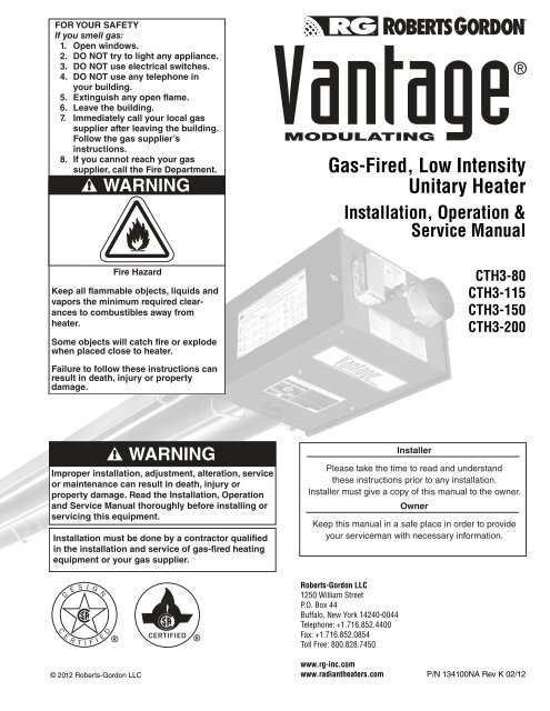
FOR YOUR SAFETY<br />
If you smell gas:<br />
1. Open windows.<br />
2. DO NOT try to light any appliance.<br />
3. DO NOT use electrical switches.<br />
4. DO NOT use any telephone in<br />
your building.<br />
5. Extinguish any open flame.<br />
6. Leave the building.<br />
7. Immediately call your local gas<br />
supplier after leaving the building.<br />
Follow the gas supplier’s<br />
instructions.<br />
8. If you cannot reach your gas<br />
supplier, call the Fire Department.<br />
WARNING<br />
Gas-Fired, Low Intensity<br />
Unitary Heater<br />
Installation, Operation &<br />
Service Manual<br />
Fire Hazard<br />
Keep all flammable objects, liquids and<br />
vapors the minimum required clearances<br />
to combustibles away from<br />
heater.<br />
Some objects will catch fire or explode<br />
when placed close to heater.<br />
CTH3-80<br />
CTH3-115<br />
CTH3-150<br />
CTH3-200<br />
Failure to follow these instructions can<br />
result in death, injury or property<br />
damage.<br />
WARNING<br />
Improper installation, adjustment, alteration, service<br />
or maintenance can result in death, injury or<br />
property damage. Read the Installation, Operation<br />
and Service Manual thoroughly before installing or<br />
servicing this equipment.<br />
Installation must be done by a contractor qualified<br />
in the installation and service of gas-fired heating<br />
equipment or your gas supplier.<br />
Installer<br />
Please take the time to read and understand<br />
these instructions prior to any installation.<br />
Installer must give a copy of this manual to the owner.<br />
Owner<br />
Keep this manual in a safe place in order to provide<br />
your serviceman with necessary information.<br />
© 2012 <strong>Roberts</strong>-<strong>Gordon</strong> LLC<br />
<strong>Roberts</strong>-<strong>Gordon</strong> LLC<br />
1250 William Street<br />
P.O. Box 44<br />
Buffalo, New York 14240-0044<br />
Telephone: +1.716.852.4400<br />
Fax: +1.716.852.0854<br />
Toll Free: 800.828.7450<br />
www.rg-inc.com<br />
www.radiantheaters.com<br />
P/N 134100NA Rev K 02/12
TABLE OF CONTENTS<br />
SECTION 1: Heater Safety...................................................... 1<br />
1.1 Manpower Requirements ............................................. 1<br />
1.2 Safety Labels and Their Placement ............................. 1<br />
1.3 California Proposition 65 .............................................. 1<br />
SECTION 2: Installer Responsibility ..................................... 4<br />
2.1 Wall Tag ....................................................................... 4<br />
2.2 Corrosive Chemicals.................................................... 4<br />
2.3 National Standards and Applicable Codes .................. 4<br />
SECTION 3: Clearances to Combustibles............................. 5<br />
3.1 Required Clearances to Combustibles......................... 5<br />
SECTION 4: National Standards and Applicable Codes ..... 9<br />
4.1 Gas Codes................................................................... 9<br />
4.2 Aircraft Hangars ........................................................... 9<br />
4.3 Public Garages ............................................................ 9<br />
4.4 Electrical ...................................................................... 9<br />
4.5 Venting......................................................................... 9<br />
4.6 High Altitude ................................................................ 9<br />
SECTION 5: Major Components .......................................... 10<br />
5.1 Standard Parts List .................................................... 11<br />
SECTION 6: Heater Installation............................................ 12<br />
6.1 Burner Tube Installation ............................................ 16<br />
6.2 Tube Clamp Package Installation.............................. 16<br />
6.3 Coupling and Tube Assembly.................................... 17<br />
6.4 Turbulator Installation ................................................ 18<br />
6.5 Reflector Installation .................................................. 19<br />
6.6 Burner Installation...................................................... 21<br />
SECTION 7: Optional Heater Accessories.......................... 22<br />
7.1 U-Tube Configuration.................................................. 22<br />
7.2 Elbow Package Configuration..................................... 25<br />
7.3 Reflector Side Extension ............................................ 27<br />
7.4 Lower Clearance Shield Installation ........................... 28<br />
7.5 Two-Foot Decorative Grille Installation ....................... 28<br />
7.6 Protective Grille Installation ........................................ 30<br />
SECTION 8: Venting.............................................................. 31<br />
8.1 Venting....................................................................... 31<br />
8.2 Unvented Operation................................................... 31<br />
8.3 Horizontal Venting...................................................... 32<br />
8.4 Vertical Venting.......................................................... 32<br />
8.5 Unvented Operation Tube Termination ...................... 32<br />
8.6 Length Requirements ................................................ 32<br />
8.7 Horizontal Ventilation 4" (10 cm) Pipe........................ 32<br />
8.8 Vertical Ventilation 4" (10 cm) Pipe............................ 33<br />
8.9 Common Side Wall Venting ....................................... 33<br />
8.10 Common Vertical Venting ........................................ 34<br />
8.11 Outside Combustion Air Supply ............................... 35<br />
SECTION 9: Gas Piping........................................................ 37<br />
SECTION 10: Wiring.............................................................. 39<br />
10.1 Standard Heater Configuration ................................ 39<br />
10.2 Central and Satellite Heaters (Zoning Capability).... 40<br />
10.3 Communication Wiring within a Zone of Heaters..... 42<br />
10.3 Communication Wiring within a Zone of Heaters<br />
(continued).............................................................. 43<br />
10.4 Heat Demand Control Wiring................................... 44<br />
10.5 Internal Wiring.......................................................... 52<br />
10.6 Ladder Diagram....................................................... 53<br />
10.7 Line Voltage Power Wiring ....................................... 54<br />
10.8 Electrical Connection to the Burner ......................... 54<br />
10.9 Low Voltage Control Wiring Installation.................... 55<br />
SECTION 11: Operation and Maintenance.......................... 56<br />
11.1 Sequence of Operation ............................................ 56<br />
11.2 To Shut Off Heater.................................................... 56<br />
11.3 To Start Heater ......................................................... 56<br />
11.4 Pre-Season Maintenance and Annual Inspection..... 56<br />
SECTION 12: Troubleshooting............................................. 59<br />
12.1 Control LED ............................................................. 60<br />
12.2 General LED Codes ................................................ 60<br />
12.3 Troubleshooting Flow Chart..................................... 62<br />
12.4 Manifold Gas Pressure Measurement...................... 64<br />
12.5 Pneumatic Connections........................................... 65<br />
SECTION 13: Replacement Parts ........................................ 66<br />
SECTION 14: General Specifications.................................. 69<br />
14.1 Material Specifications............................................. 69<br />
14.2 Heater Specifications............................................... 69<br />
14.3 Suspension Specifications....................................... 69<br />
14.4 Controls Specifications ............................................ 69<br />
SECTION 15: The ROBERTS GORDON ® VANTAGE ®<br />
MODULATING Warranty................................ 71<br />
There are references in this manual to various trademarks. All trademarks mentioned herein, whether registered or not, are the<br />
property of their respective owners. <strong>Roberts</strong>-<strong>Gordon</strong> LLC is not sponsored by or affiliated with any of the trademark or registered<br />
trademark owners, and make no representations about them, their owners, their products or services. <strong>Roberts</strong>-<strong>Gordon</strong><br />
LLC is not sponsored by or affiliated with BACnet ® or LonWorks®.<br />
© 2012 <strong>Roberts</strong>-<strong>Gordon</strong> LLC<br />
All rights reserved. No part of this work covered by the copyrights herein may be reproduced<br />
or copied in any form or by any means - graphic, electronic, or mechanical, including<br />
photocopying, recording, taping or information storage and retrieval systems - without the<br />
written permission of <strong>Roberts</strong>-<strong>Gordon</strong> LLC.<br />
Printed in U.S.A.
TABLE OF FIGURES<br />
Figure 1: Top and Bottom Panel Label Placement .................... 2<br />
Figure 2: Side and Back Panel Label Placement...................... 3<br />
Figure 3: Standard Reflector ..................................................... 5<br />
Figure 4: One Side Reflector..................................................... 6<br />
Figure 5: Two Side Reflectors ................................................... 6<br />
Figure 6: 45° Tilt Reflector ........................................................ 6<br />
Figure 7: U-Tube, Standard Reflector........................................ 7<br />
Figure 8: U-Tube, 45°................................................................ 7<br />
Figure 9: U-Tube, Opposite 45° Reflector ................................. 7<br />
Figure 10: 2-Foot Deco Grille and Protective Grille ................... 8<br />
Figure 11: Lower Clearance Shield ........................................... 8<br />
Figure 12: Venting ..................................................................... 8<br />
Figure 13: Major Component Descriptions.............................. 10<br />
Figure 14: Critical Hanger Placement ..................................... 13<br />
Figure 15: Linear Heater Assembly Overview ........................ 14<br />
Figure 16: Linear Heater Layout Overview.............................. 15<br />
Figure 17: U-Tube Heater Assembly Overview ...................... 23<br />
Figure 18: U-Tube Heater Layout Overview ........................... 24<br />
Figure 19: Reflector Joint Detail .............................................. 26<br />
Figure 20: Tube Termination................................................... 32<br />
Figure 21: Gas Connection with Flexible Gas Hose ............... 38<br />
Figure 22: Zone Sensor Wiring Diagram................................. 39<br />
Figure 23: Central Heater Jumper Settings............................. 40<br />
Figure 24: Satellite Heater Jumper Setting.............................. 41<br />
Figure 25: Communication Wiring within a Zone of Heaters ... 42<br />
Figure 25: Communication Wiring within a Zone of Heaters<br />
(continued)............................................................. 43<br />
Figure 26: Thermostat Control Wiring Diagram....................... 44<br />
Figure 27: Analog Control Signal Wiring Diagram................... 47<br />
Figure 28: Potentiometer Control Wiring Diagram................... 48<br />
Figure 29: <strong>Modulating</strong> Thermostat Wiring Diagram<br />
(LonWorks ® [4-20 mA] optional)............................. 49<br />
Figure 30: <strong>Modulating</strong> Thermostat Wiring Diagram<br />
(LonWorks ®<br />
[2-10Vdc with 500 Ohm resistor]<br />
optional)................................................................. 50<br />
Figure 31: <strong>Modulating</strong> Thermostat Wiring Diagram<br />
with BACnet ® (optional) ......................................... 51<br />
LIST OF TABLES<br />
Table 1: Contents of Burner Carton........................................ 11<br />
Table 2: Contents of Core and Extension Packages .............. 11<br />
Table 3: CTH3-Series Component Package Guide................ 11<br />
Table 4: Cable Requirements ................................................. 46
SECTION 1: HEATER SAFETY<br />
SECTION 1: HEATER SAFETY<br />
Your Safety is Important to Us!<br />
This symbol is used throughout<br />
the manual to notify you of possible<br />
fire, electrical or burn hazards.<br />
Please pay special attention when<br />
reading and following the<br />
warnings in these sections.<br />
Installation, Service and Annual Inspection of heater<br />
must be done by a contractor qualified in the<br />
installation and service of gas-fired heating<br />
equipment.<br />
Read this manual carefully before installation,<br />
operation or service of this equipment.<br />
This heater is designed for heating nonresidential<br />
indoor spaces. Do not install in residential spaces.<br />
These instructions, the layout drawing, local codes<br />
and ordinances, and applicable standards that apply<br />
to gas piping, electrical wiring, venting, etc. must be<br />
thoroughly understood before proceeding with the<br />
installation.<br />
Protective gear is to be worn during installation,<br />
operation and service. Thin sheet metal parts,<br />
including the aluminum reflector portion of the heater<br />
and the various venting components, have sharp<br />
edges. To prevent injury, the use of work gloves is<br />
recommended. The use of gloves will also prevent<br />
the transfer of body oils from the hands to the surface<br />
of the reflector.<br />
Before installation, check that the local distribution<br />
conditions, nature of gas and pressure, and<br />
adjustment of the appliance are compatible.<br />
This heater must be applied and operated under the<br />
general concepts of reasonable use and installed<br />
using best building practices.<br />
This appliance is not intended for use by persons<br />
(including children) with reduced physical, sensory or<br />
mental capabilities, or lack of experience and<br />
knowledge, unless they have been given supervision<br />
or instruction concerning use of the appliance by a<br />
person responsible for their safety. Children should<br />
be supervised to ensure that they do no play with the<br />
appliance.<br />
For additional copies of the Installation, Operation<br />
and Service Manual, please contact <strong>Roberts</strong>-<strong>Gordon</strong><br />
LLC.<br />
1.1 Manpower Requirements<br />
To prevent personal injury and damage to the heater,<br />
two persons will be required for installation.<br />
1.2 Safety Labels and Their Placement<br />
Product safety signs or labels should be replaced by<br />
the product user when they are no longer legible.<br />
Please contact <strong>Roberts</strong>-<strong>Gordon</strong> LLC or your ROB-<br />
ERTS GORDON ® independent distributor to obtain<br />
replacement signs or labels. See Page 2, Figure 1<br />
through Page 3, Figure 2.<br />
1.3 California Proposition 65<br />
In accordance with California Proposition 65 requirements,<br />
a warning label must be placed in a highly<br />
visible location on the outside of the equipment (i.e.,<br />
near equipment’s serial plate). See label placement<br />
drawing on Page 2, Figure 1 for label location. Avoid<br />
placing label on areas with extreme heat, cold, corrosive<br />
chemicals or other elements. To order additional<br />
labels, please contact <strong>Roberts</strong>-<strong>Gordon</strong> LLC or your<br />
ROBERTS GORDON ® independent distributor.<br />
1 of 71
CTH3-SERIES INSTALLATION, OPERATION AND SERVICE MANUAL<br />
FIGURE 1: Top and Bottom Panel Label Placement<br />
Logo Label<br />
Bottom<br />
Panel<br />
Rating Plate Label<br />
Proposition 65 Label<br />
Top Panel<br />
Description<br />
Part Number<br />
Logo Label 91013212<br />
Rating Plate Label 91010401<br />
Gas Connection Label 91018122<br />
Proposition 65 Label 91070015<br />
Gas Connection Label<br />
2 of 71
SECTION 1: HEATER SAFETY<br />
FIGURE 2: Side and Back Panel Label Placement<br />
Control Side Panel<br />
Clearances to Combustibles Label<br />
Control Side Panel (Inside)<br />
Wiring Label<br />
N.O.<br />
COM<br />
Inside Bottom Panel<br />
Carbon Monoxide Hazard Label<br />
Vent Length Label<br />
Low Voltage<br />
Connection<br />
Label<br />
Back Panel<br />
Description<br />
Part Number<br />
Clearances to Combustibles Label 91013415<br />
Wiring Label 91013303<br />
Carbon Monoxide Hazard Label 91039501<br />
Low Voltage Connection Label 91039700<br />
Vent Length Label 91039500<br />
Lighting Instruction Plate Label 91029602<br />
Lighting Instruction Plate Label<br />
3 of 71
CTH3-SERIES INSTALLATION, OPERATION AND SERVICE MANUAL<br />
SECTION 2: INSTALLER RESPONSIBILITY<br />
The installer is responsible for the following:<br />
• To install the heater, as well as the gas and<br />
electrical supplies, in accordance with applicable<br />
specifications and codes. <strong>Roberts</strong>-<strong>Gordon</strong> LLC<br />
recommends the installer contact a local Building<br />
Inspector or Fire Marshal for guidance.<br />
• To use the information given in a layout drawing<br />
and in the manual together with the cited codes<br />
and regulations to perform the installation.<br />
• To install the heater in accordance with the<br />
clearances to combustibles.<br />
• To furnish all needed materials not furnished as<br />
standard equipment.<br />
• To plan location of supports.<br />
• To provide access to burners for servicing on all<br />
sides, for burner removal.<br />
• To provide the owner with a copy of this<br />
installation, operation and service manual.<br />
• To never use heater as support for a ladder or<br />
other access equipment and never hang or suspend<br />
anything from heater.<br />
• To ensure there is adequate air circulation around<br />
the heater and to supply air for combustion, ventilation<br />
and distribution in accordance with local<br />
codes.<br />
• To safely and adequately install heater using<br />
materials with a minimal working load of 75 lbs<br />
(33 kg).<br />
• To ensure the heater is placed in a approved<br />
application.<br />
2.1 Wall Tag<br />
A laminated wall tag is available for the heater as a<br />
permanent reminder of the safety instructions and<br />
the importance of the required clearances to<br />
combustibles. Please contact <strong>Roberts</strong>-<strong>Gordon</strong> LLC<br />
or your ROBERTS GORDON ®<br />
independent<br />
distributor to obtain the wall tag. Affix the tag by<br />
peeling off the backing of the adhesive strips on the<br />
rear surface and position the tag on a wall near the<br />
heater (e.g. thermostat or ROBERTS GORDON ®<br />
Controller).<br />
A copy of the wall tag (P/N 91037912) is illustrated on<br />
the back cover. For an immediate solution, you may<br />
affix this copy on the wall near the heater.<br />
Know your model number and installed configuration.<br />
Model number and installed configuration are found<br />
4 of 71<br />
on the burner and in the Installation, Operation and<br />
Service Manual. See Page 5, Figure 3 through Page<br />
8, Figure 12. Write the proper clearance dimensions<br />
in permanent ink according to your model number<br />
and configuration in the open spaces on the tag.<br />
2.2 Corrosive Chemicals<br />
CAUTION<br />
Product Damage Hazard<br />
Do not use heater in area containing<br />
corrosive chemicals.<br />
Refer to appropriate Material Safety Data<br />
Sheets (MSDS).<br />
Failure to follow these instructions can result<br />
in product damage.<br />
<strong>Roberts</strong>-<strong>Gordon</strong> LLC cannot be responsible for<br />
ensuring that all appropriate safety measures are<br />
undertaken prior to installation; this is entirely the<br />
responsibility of the installer. It is essential that the<br />
contractor, the sub-contractor, or the owner identifies<br />
the presence of combustible materials, corrosive<br />
chemicals or halogenated hydrocarbons* anywhere<br />
in the premises.<br />
* Halogenated Hydrocarbons are a family of chemical<br />
compounds characterized by the presence of halogen<br />
elements (fluorine, chlorine, bromine, etc.). These compounds<br />
are frequently used in refrigerants, cleaning<br />
agents, solvents, etc. If these compounds enter the air<br />
supply of the burner, the life span of the heater components<br />
will be greatly reduced. An outside air supply must<br />
be provided to the burners whenever the presence of<br />
these compounds is suspected. Warranty will be invalid if<br />
the heater is exposed to halogenated hydrocarbons.<br />
2.3 National Standards and Applicable Codes<br />
All appliances must be installed in accordance with<br />
the latest revision of the applicable standards and<br />
national codes. This refers also to the electric, gas<br />
and venting installation. Note: Additional standards<br />
for installations in Public Garages, Aircraft Hangars,<br />
etc. may be applicable.
SECTION 3: CLEARANCES TO COMBUSTIBLES<br />
SECTION 3: CLEARANCES TO COMBUSTIBLES<br />
3.1 Required Clearances to Combustibles<br />
Clearances are the required distances that<br />
combustible objects must be away from the heater to<br />
prevent serious fire hazards. Combustibles are<br />
materials, that may catch on fire and include common<br />
items such as wood, paper, rubber, fabric, etc.<br />
Maintain clearances to combustibles at all times<br />
for safety.<br />
Clearances for all heater models are located on the<br />
burner of the heater and on Page 5, Figure 3 through<br />
Page 8, Figure 12 in this manual. Check the<br />
clearances on each burner for the model heater<br />
being installed to make sure the product is suitable<br />
for your application and the clearances are<br />
maintained. Read and follow the safety guidelines<br />
below:<br />
• Keep gasoline or other combustible materials<br />
including flammable objects, liquids, dust or<br />
vapors away from this heater or any other<br />
appliance<br />
• The stated clearance to combustible represents a<br />
surface temperature of 90° F (50°C) above room<br />
temperature. Building materials with a low heat<br />
tolerance (such as plastics, vinyl siding, canvas,triply,<br />
etc.) may be subject to degradation at<br />
lower temperatures. It is the installer’s responsibility<br />
to assure that adjacent materials are protected<br />
from degradation.<br />
• Maintain clearances from heat sensitive<br />
equipment and workstations.<br />
• Maintain clearances from vehicles parked below<br />
the heater.<br />
• Maintain clearances from swinging and overhead<br />
doors, overhead cranes, vehicle lifts, partitions,<br />
storage racks, hoists, building construction, etc.<br />
WARNING<br />
Fire Hazard<br />
Keep all flammable objects, liquids and<br />
vapors the minimum required clearances to<br />
combustibles away from heater.<br />
Some objects will catch fire or explode when<br />
placed close to heater.<br />
Failure to follow these instructions can result<br />
in death, injury or property damage.<br />
• In locations used for the storage of combustible<br />
materials, signs must be posted to specify the<br />
maximum permissible stacking height to maintain<br />
required clearances from the heater to the<br />
combustibles. Signs must be posted adjacent to<br />
the heater thermostat. In the absence of a<br />
thermostat, signs must be posted in a<br />
conspicuous location.<br />
• Consult local Fire Marshal, Fire Insurance Carrier<br />
or other authorities for approval of proposed<br />
installation when there is a possibility of exposure<br />
to combustible airborne materials or vapors.<br />
• Hang heater in accordance to the minimum suspension<br />
requirements on Page 13, Figure 14.<br />
• If the radiant tubes must pass through the building<br />
structure, be sure that adequate sleeving and fire<br />
stop is installed to prevent scorching and/or fire<br />
hazard.<br />
NOTE: 1. All dimensions are from the surfaces of all tubes, couplings and elbows.<br />
2. Clearances B, C and D can be reduced by 50% after 25' (7.5 m) of tubing downstream<br />
from where the burner and burner tube connect.<br />
FIGURE 3: STANDARD REFLECTOR<br />
(inches)<br />
(centimeters)<br />
Model A B C D A B C D<br />
CTH3-80 6 38 66 38 16 97 168 97<br />
CTH3-115 6 46 77 46 16 117 196 117<br />
CTH3-150 6 50 80 50 16 127 204 127<br />
CTH3-200 8 52 82 52 21 133 209 133<br />
5 of 71
CTH3-SERIES INSTALLATION, OPERATION AND SERVICE MANUAL<br />
NOTE: 1. All dimensions are from the surfaces of all tubes, couplings and elbows.<br />
2. Clearances B, C and D can be reduced by 50% after 25' (7.5 m) of tubing downstream<br />
from where the burner and burner tube connect.<br />
FIGURE 4: ONE SIDE REFLECTOR<br />
(inches)<br />
(centimeters)<br />
A<br />
C<br />
B<br />
D<br />
Model A B C D A B C D<br />
CTH3-80 6 9 70 54 16 23 178 138<br />
CTH3-115 6 9 83 65 16 23 211 166<br />
CTH3-150 6 9 86 69 16 23 219 176<br />
CTH3-200 8 9 88 73 21 23 224 186<br />
FIGURE 5: TWO SIDE REFLECTORS<br />
(inches)<br />
(centimeters)<br />
A<br />
C<br />
B<br />
D<br />
Model A B C D A B C D<br />
CTH3-80 6 25 72 25 16 64 183 64<br />
CTH3-115 6 32 84 32 16 82 214 82<br />
CTH3-150 6 35 88 35 16 89 224 89<br />
CTH3-200 8 40 91 40 21 102 232 102<br />
FIGURE 6: 45° TILT REFLECTOR<br />
(inches)<br />
(centimeters)<br />
Model A B C D A B C D<br />
CTH3-80 8 8 66 60 21 21 168 153<br />
CTH3-115 10 8 78 69 26 21 199 176<br />
CTH3-150 12 8 84 74 31 21 214 188<br />
CTH3-200 12 8 85 79 31 21 216 201<br />
6 of 71
SECTION 3: CLEARANCES TO COMBUSTIBLES<br />
NOTE: 1. All dimensions are from the surfaces of all tubes, couplings and elbows.<br />
2. Clearances B, C and D can be reduced by 50% after 25' (7.5 m) of tubing downstream<br />
from where the burner and burner tube connect.<br />
FIGURE 7: U-TUBE, STANDARD REFLECTOR<br />
(inches)<br />
(centimeters)<br />
A<br />
B<br />
C<br />
D<br />
Model A B C D A B C D<br />
CTH3-80 6 38 69 37 16 97 176 94<br />
CTH3-115 6 46 79 43 16 117 201 110<br />
CTH3-150 6 50 84 47 16 127 214 120<br />
CTH3-200 8 54 87 51 21 138 221 130<br />
FIGURE 8: U-TUBE, 45°<br />
A<br />
B<br />
D<br />
C<br />
(inches)<br />
(centimeters)<br />
Model A B C D A B C D<br />
CTH3-80 8 8 66 46 21 21 168 117<br />
CTH3-115 8 8 78 61 21 21 199 155<br />
CTH3-150 8 8 84 66 21 21 214 168<br />
CTH3-200 8 8 85 70 21 21 216 178<br />
FIGURE 9: U-TUBE, OPPOSITE 45° REFLECTOR<br />
(inches)<br />
(centimeters)<br />
A<br />
B<br />
D<br />
C<br />
Model A B C D A B C D<br />
CTH3-80 8 60 66 22 21 153 168 56<br />
CTH3-115 10 70 78 22 26 178 199 56<br />
CTH3-150 12 74 84 22 31 188 214 56<br />
CTH3-200 12 76 85 22 31 194 216 56<br />
7 of 71
CTH3-SERIES INSTALLATION, OPERATION AND SERVICE MANUAL<br />
NOTE: 1. All dimensions are from the surfaces of all tubes, couplings and elbows.<br />
2. Clearances B, C and D can be reduced by 50% after 25' (7.5 m) of tubing downstream<br />
from where the burner and burner tube connect.<br />
FIGURE 10: 2-FOOT DECO GRILLE AND PROTECTIVE GRILLE<br />
(inches)<br />
(centimeters)<br />
A<br />
C<br />
B<br />
D<br />
Model A B C D A B C D<br />
CTH3-80 6 38 66 38 16 97 168 97<br />
CTH3-115 6 46 77 46 16 117 196 117<br />
CTH3-150 6 50 80 50 16 127 204 127<br />
CTH3-200 8 52 82 52 21 133 209 133<br />
FIGURE 11: LOWER CLEARANCE SHIELD*<br />
(inches)<br />
(centimeters)<br />
A<br />
C<br />
B<br />
D<br />
Model A B C D A B C D<br />
CTH3-80 6 40 38 40 16 102 97 102<br />
CTH3-115 6 54 48 54 16 138 122 138<br />
CTH3-150 6 55 50 55 16 140 127 140<br />
CTH3-200 - UNAPPROVED - - UNAPPROVED -<br />
*When installed in the first 10' (3 m).<br />
FIGURE 12: VENTING<br />
Unvented<br />
Radiant Tubes<br />
Vented<br />
A<br />
E<br />
Vent<br />
Pipes<br />
F<br />
(inches)<br />
(centimeters)<br />
Model A E F A E F<br />
CTH3-80 20 24 18 51 61 46<br />
CTH3-115 20 24 18 51 61 46<br />
CTH3-150 20 30 18 51 77 46<br />
CTH3-200 20 30 18 51 77 46<br />
8 of 71
SECTION 4: NATIONAL STANDARDS AND APPLICABLE CODES<br />
SECTION 4: NATIONAL STANDARDS AND<br />
APPLICABLE CODES<br />
4.1 Gas Codes<br />
The type of gas appearing on the nameplate<br />
must be the type of gas used. Installation must<br />
comply with national and local codes and<br />
requirements of the local gas company.<br />
United States: Refer to National Fuel Gas Code<br />
NFPA 54/ANSI Z223.1 - latest revision.<br />
Canada: Refer to Natural Gas and Propane<br />
Installation Code CSA B149.1 - latest revision.<br />
4.2 Aircraft Hangars<br />
Installation in aircraft hangars must be in<br />
accordance with the following codes:<br />
United States: Refer to Standard for Aircraft<br />
Hangars, NFPA 409 - latest revision.<br />
Canada: Refer to Natural Gas and Propane<br />
Installation Code CSA B149.1 - latest revision.<br />
In aircraft storage and servicing areas, heaters<br />
shall be installed at least 10' (3 m) above the<br />
upper surface of wings or of engine enclosures<br />
of the highest aircraft which may be housed in<br />
the hangar. The measurement shall be made<br />
from the wing or engine enclosure (whichever is<br />
higher from the floor) to the bottom of the heater.<br />
• In shops, offices and other sections of aircraft<br />
hangars communicating with aircraft storage or<br />
servicing areas, heaters shall be installed not<br />
less than 8' (2.4 m) above the floor.<br />
• Suspended or elevated heaters shall be so<br />
located in all spaces of aircraft hangars that they<br />
shall not be subject to injury by aircraft, cranes,<br />
movable scaffolding or other objects. Provisions<br />
shall be made to assure accessibility to<br />
suspended heaters for recurrent maintenance<br />
purposes.<br />
4.3 Public Garages<br />
Installation in garages must be in accordance<br />
with the following codes:<br />
United States: Refer to Standard for Parking<br />
Structures NFPA 88A - latest revision or the<br />
Code for Motor Fuel Dispensing Facilities and<br />
Repair Garages, NFPA 30A - latest revision.<br />
Canada: Refer to Natural Gas and Propane<br />
Installation Code CSA B149.1 - latest revision.<br />
• Heaters must not be installed less than 8'<br />
(2.4 m) above the floor. Minimum clearances to<br />
combustibles must be maintained from vehicles<br />
parked below the heater.<br />
• When installed over hoists, minimum<br />
clearances to combustibles must be maintained<br />
from the upper most point of objects on the hoist.<br />
4.4 Electrical<br />
The heater must be electrically grounded in<br />
accordance with the following codes:<br />
United States: Refer to National Electrical Code ® ,<br />
NFPA 70 - latest revision. Wiring must conform to<br />
the most current National Electrical Code ® , local<br />
ordinances and any special diagrams furnished.<br />
Canada: Refer to Canadian Electrical Code,<br />
CSA C22.1 Part 1 - latest revision.<br />
4.5 Venting<br />
The venting must be installed in accordance with<br />
the requirements within this manual and the<br />
following codes:<br />
United States: Refer to National Fuel Gas Code<br />
NFPA 54/ANSI Z223.1 - latest revision.<br />
Canada: Refer to Natural Gas and Propane<br />
Installation Code CSA B149.1 - latest revision.<br />
4.6 High Altitude<br />
These heaters are approved for installations up<br />
to 2000' (610 m)(US), 4500' (1370 m)(Canada)<br />
without modification. Consult factory if US<br />
installation is above 2000' (610 m) or Canadian<br />
installation is above 4500' (1370 m).<br />
9 of 71
CTH3-SERIES INSTALLATION, OPERATION AND SERVICE MANUAL<br />
SECTION 5: MAJOR COMPONENTS<br />
FIGURE 13: Major Component Descriptions<br />
Burner with Tube Gasket<br />
Must be installed with the<br />
flame observation<br />
window facing down.<br />
Reflector<br />
(Aluminum or<br />
Stainless<br />
Steel)<br />
Alternate overlap as<br />
shown on overview and<br />
on Page 15, Figure 16.<br />
Minimum overlap is 6" (16 cm).<br />
Burner Tube<br />
Supplied in 10'<br />
(3 m) lengths. Burner<br />
tube is always the first tube<br />
after the burner.<br />
Tube<br />
Heat treated<br />
aluminized tube supplied<br />
in 10' (3 m) lengths.<br />
Tube and Reflector Hanger<br />
with Clamp Package<br />
Position this hanger no more<br />
than 4" (10 cm) away from the<br />
burner.<br />
Tube and Reflector Hanger<br />
Suspend system from these<br />
hangers.<br />
Coupling Assembly<br />
with Lock<br />
Reflector End Cap<br />
Punch out center<br />
section to<br />
accommodate tube.<br />
Vent Adapter<br />
Reflector Support Strap &<br />
Wire Form<br />
Flex Gas Line with<br />
Shut Off Cock<br />
Turbulator<br />
Turbulator must<br />
be installed in the last<br />
standard section of tube.<br />
Turbulator is not required on the<br />
CTH3-200. For installation see<br />
Page 18, Section 6.4.<br />
10 of 71
SECTION 5: MAJOR COMPONENTS<br />
5.1 Standard Parts List<br />
Table 1: Contents of Burner Carton<br />
Part No. Description CTH3-80 CTH3-115 CTH3-150 CTH3-200<br />
034XXXXX Burner Assembly (Rate and Fuel Varies) 1 1 1 1<br />
02568200 Gasket (Burner to Burner Tube) 1 1 1 1<br />
134100NA Installation, Operation and Service Manual 1 1 1 1<br />
94273914 Hex Head Bolts 5/16-18 Rolok 4 4 4 4<br />
96411600 Split Lock Washer 4 4 4 4<br />
91201708 Pipe Nipple (Black) 1/2" NPT x 4" 1 1 1 1<br />
*91412200 Flexible Stainless Steel Gas Hose - 1/2" NPT (US Models Only) 1 1 - -<br />
*91412204 Flexible Stainless Steel Gas Hose - 3/4" NPT (US Models Only) - - 1 1<br />
03051503 Turbulator Adapter 1 1 1 -<br />
03051504 Turbulator, Aluminized Steel 3 3 1 -<br />
91317310 Wire Terminal Receptacle.187 x.032 8 8 8 8<br />
91309605 Cable Grommet with Tie 1 1 1 1<br />
*Canadian Models: Rubber (Type 1) Gas Hoses available as an accessory. See Page 37, Section 9.<br />
Table 2: Contents of Core and Extension Packages<br />
Core Packages (Aluminized) Extension Packages (Aluminized)<br />
Part No. Description 10' (3m) 20' (6m) 30' (9m) 40' (12m) 10' (3m) 20' (6m) 30' (9m) 40' (12m)<br />
91409408 Tube, HT Aluminized, 10' (3m) - 1 2 3 1 2 3 4<br />
03051101 Burner Tube, ALUMI-THERM ® Steel, 10' (3m) - - 1 1 - - - -<br />
03051601 Burner Tube, HT ALUMI-THERM ® Steel, 10' (3m) 1 1 - - - - - -<br />
01312700 Coupling Assembly - 1 2 3 1 2 3 4<br />
02750303 Standard Reflector, 8' (2.6m) 2 3 4 6 2 3 4 6<br />
02750800 End Cap 2 2 2 2 - - - -<br />
03090100 Tube and Reflector Hanger 2 3 4 5 1 2 3 4<br />
91907302 S-Hook 2 3 4 5 1 2 3 4<br />
03050010 Reflector Support Package (Strap, Wire Form, Screws) 1 2 3 5 2 3 4 6<br />
91107720 U-Clip Package 1 1 1 1 1 1 1 1<br />
90502700 Vent Adapter 1 1 1 1 - - - -<br />
01318901 Tube Clamp Package 1 1 1 1 - - - -<br />
Part Number<br />
CP10ALUM<br />
CP20ALUM<br />
CP30ALUM<br />
CP40ALUM<br />
EXP10ALUM<br />
EXP20ALUM<br />
EXP30ALUM<br />
EXP40ALUM<br />
Table 3: CTH3-Series Component Package Guide<br />
Model Tubing Length Core Packages<br />
Minimum<br />
Aluminized<br />
CTH3-80 20' (6m) CP20ALUM<br />
CTH3-115 30' (9m) CP30ALUM<br />
CTH3-150 40' (12m) CP40ALUM<br />
CTH3-200 50' (15m) CP30ALUM + EXP20ALUM<br />
Additional tubing length may be added to heater. Tubing must be heat-treated, aluminized or porcelain<br />
coated. Any additional tubing lengths are considered as vent length for length determination. Maximum<br />
venting length for minimum heater length is 45' (13.7 m) total.<br />
11 of 71
CTH3-SERIES INSTALLATION, OPERATION AND SERVICE MANUAL<br />
SECTION 6: HEATER INSTALLATION<br />
WARNING<br />
Expansion and contraction of the tube dictates that<br />
the minimum suspension lengths in the table on<br />
Page 13, Figure 14 be maintained.<br />
Severe Injury Hazard<br />
Secure burner to burner tube with bolts and<br />
lockwashers.<br />
Hang heater with materials with a minimum<br />
working load of 75 lbs (33 kg).<br />
Failure to follow these instructions can result<br />
in death, injury or property damage.<br />
WARNING<br />
Cut/Pinch Hazard<br />
Wear protective gear during installation,<br />
operation and service.<br />
Edges are sharp.<br />
Failure to follow these instructions can result<br />
in injury.<br />
To ensure your safety, and comply with the terms of<br />
the warranty, all units must be installed in<br />
accordance with these instructions.<br />
The gas or the electrical supply lines must not be<br />
used to support the heater.<br />
Do not locate the gas or electric supply lines directly<br />
over the path of the flue products from the heater.<br />
The heater must be installed in a location that it is<br />
readily accessible for servicing.<br />
The heater must be installed in accordance with<br />
clearances to combustibles as indicated on the<br />
heater and in this instruction manual.<br />
The gas inlet pressure must be maintained as<br />
indicated on the rating plate.<br />
Typical installation configurations are shown on Page<br />
13, Figure 14.<br />
12 of 71
SECTION 6: HEATER INSTALLATION<br />
FIGURE 14: Critical Hanger Placement<br />
Typical Suspension Details<br />
Beam Clamp<br />
Anchor<br />
Screw Hook<br />
3/8"<br />
Concrete Beam<br />
Wood Beam<br />
Locknut<br />
24" min.*<br />
(61 cm)<br />
Rod 3/8"<br />
“X”*<br />
Chain Size<br />
3/16"<br />
Minimum<br />
Washers<br />
S-hooks<br />
Turnbuckle<br />
Not Included<br />
* Allows for thermal expansion of system<br />
S-hooks<br />
Side View<br />
Hanger<br />
Reflector<br />
Hanger<br />
Must Be Within 4" (10 cm)<br />
Front View<br />
45° Angle<br />
Description<br />
Part Number<br />
S-Hook 91907302<br />
Tube/Reflector Hanger 03090100<br />
Run Length Typical Expansion Minimum “X” Length<br />
10' - 50' ±1" (3 cm) 12"<br />
51' - 60' ±2" (5 cm) 18"<br />
61' - 70' ±3" (8 cm) 24"<br />
13 of 71
CTH3-SERIES INSTALLATION, OPERATION AND SERVICE MANUAL<br />
FIGURE 15: Linear Heater Assembly Overview<br />
Reflector End Cap<br />
Burner<br />
Tube Clamp<br />
Package<br />
Burner Tube<br />
Tube and Reflector Hanger<br />
Coupling<br />
Reflector Support<br />
Reflector<br />
Tube<br />
Turbulator<br />
(With Select Models)<br />
Vent Adapter<br />
U-Clips<br />
14 of 71
SECTION 6: HEATER INSTALLATION<br />
FIGURE 16: Linear Heater Layout Overview<br />
LEGEND<br />
Burner<br />
g<br />
b<br />
c<br />
d<br />
e<br />
Reflector<br />
f<br />
Tube<br />
20' (6 m) Tube Length<br />
Tube/Reflector<br />
Hanger<br />
Coupling<br />
Assembly<br />
g<br />
b<br />
c<br />
d e e<br />
Vent Adapter<br />
f<br />
a = 14" (36 cm)<br />
reflector width (not shown)<br />
b = 2" (5 cm)<br />
end cap to burner<br />
g<br />
b<br />
c<br />
30' (9 m) Tube Length<br />
d e e e<br />
c = 2" (5 cm)<br />
end cap to hanger<br />
f<br />
d = 7'6" (229 cm)<br />
distance first hanger<br />
e = 10' (305 cm)<br />
distance between hangers<br />
g<br />
b<br />
c<br />
40' (12 m) Tube Length<br />
d e e e e<br />
f = 9.5" (24 cm)<br />
burner height<br />
g = 17.5" (44 cm)<br />
burner length<br />
f<br />
50' (15 m) Tube Length<br />
g<br />
b<br />
c<br />
d e e e e e<br />
g<br />
f<br />
b<br />
c<br />
b<br />
60' (18 m) Tube Length<br />
d e e e e e e<br />
f<br />
70' (21 m) Tube Length<br />
g<br />
b<br />
c<br />
d e e e e e e<br />
e<br />
b<br />
f<br />
80' (24 m) Tube Length<br />
15 of 71
CTH3-SERIES INSTALLATION, OPERATION AND SERVICE MANUAL<br />
Step 6.1 Burner Tube Installation<br />
NOTE:<br />
Tubing requires a downward<br />
slope of 1/2" (1.3 cm)<br />
per 20' (6 m) away<br />
from burner.<br />
Offset mounting<br />
hole must be<br />
to the top.<br />
S-hook<br />
Hanger<br />
Burner Tube<br />
7' 6" ± 1'<br />
(229 cm ± 25 cm)<br />
Weld seam<br />
must be to the<br />
bottom of the tube.<br />
Description<br />
Part Number<br />
Burner Tube<br />
03051XXX<br />
S-Hook 91907302<br />
Tube/Reflector Hanger 03090100<br />
Step 6.2 Tube Clamp Package Installation<br />
Description<br />
Part Number<br />
Tube Clamp Package 01318901<br />
Tube Clamp 01396801<br />
Bolt 97113940<br />
Flat Washer 95211600<br />
Nut 92113900<br />
Tube Clamp<br />
Flat<br />
Washer<br />
Bolt<br />
Nut<br />
(Torque 120 in/lb<br />
13.56 Nm)<br />
16 of 71
Step 6.3 Coupling and Tube Assembly<br />
A<br />
Close coupling<br />
with tab.<br />
Tab<br />
B<br />
Start Slide bar/Coupling<br />
Lock.<br />
SECTION 6: HEATER INSTALLATION<br />
Slide Bar/Coupling Lock<br />
Open<br />
3" (8 cm) to<br />
4" (10 cm)<br />
Wide End<br />
Coupling<br />
C<br />
Closed<br />
Insert tubes into coupling.<br />
D<br />
Tighten coupling to join tubes.<br />
Tube<br />
Orient coupling so that<br />
the impact block is in the<br />
2:00 or 10:00 o’clock<br />
positions.<br />
Tube<br />
Tube<br />
Description<br />
Part Number<br />
Coupling 01329600<br />
Slide bar/Coupling Lock 01329700<br />
Tube<br />
91409XXX<br />
Slide Bar/Coupling Lock<br />
Coupling<br />
Step 6.3.1 Coupling and Tube Assembly (Continued)<br />
Tighten slide bar as shown below.<br />
Drive slide bar until tight.<br />
End of slide bar should be<br />
within tolerance listed below.<br />
± 2" (5 cm)<br />
Correct slide bar<br />
dimensions<br />
Incorrect slide bar<br />
position<br />
• Repeat Step 6.3 A - D until all tubes are assembled. See Page 18, Section 6.3.2.<br />
17 of 71
CTH3-SERIES INSTALLATION, OPERATION AND SERVICE MANUAL<br />
Step 6.3.2 Coupling and Tube Assembly (Continued)<br />
Tube Length<br />
Model<br />
Minimum<br />
CTH3-80 20' (6 m)<br />
CTH3-115 30' (9 m)<br />
CTH3-150 40' (12 m)<br />
CTH3-200 50' (15 m)<br />
7' 6" ± 1'<br />
(2.3 m ± .25 m)<br />
10' ± 1'<br />
(3 m ± .25 m)<br />
Total Overall<br />
Tube Length<br />
Step 6.4 Turbulator Installation<br />
Turbulator must be installed in<br />
the last standard section of<br />
tube. Turbulator is not required<br />
on the CTH3-200.<br />
Turbulator<br />
Section<br />
Twist<br />
Turbulator Installation<br />
CTH3-80 2nd 10' Section<br />
CTH3-115 3rd 10' Section<br />
CTH3-150 4th 10' Section<br />
CTH3-200<br />
N/A<br />
Turbulator<br />
Adapter<br />
Tab<br />
Description<br />
Part Number<br />
Turbulator Adapter 03051503<br />
Turbulator Section 03051504<br />
Tube<br />
91409XXX<br />
18 of 71<br />
Fold tab around outside<br />
of tube nearest to the vent to<br />
hold turbulator in place.<br />
Pull String
SECTION 6: HEATER INSTALLATION<br />
6.5 Reflector Installation<br />
WARNING<br />
Fire Hazard<br />
Support reflector with reflector hanger<br />
and support strap.<br />
Reflector must not touch tube.<br />
Failure to follow these instructions can result<br />
in death, injury or property damage.<br />
NOTE: All tube surfaces must be covered<br />
by a reflector, except for a U-Tube.<br />
Hanger<br />
Burner Tube<br />
Reflector<br />
Description<br />
Part Number<br />
Tube/Reflector Hanger 03090100<br />
Burner Tube<br />
03051XXX<br />
Reflector 02750303<br />
19 of 71
CTH3-SERIES INSTALLATION, OPERATION AND SERVICE MANUAL<br />
Step 6.5.1 Reflector, U-Clip and Reflector Support Installation<br />
The pictorial drawings of the heater construction in<br />
Section 6 are schematic only and provide a general<br />
guideline of where hangers, reflector supports and<br />
U-clips are to be installed.<br />
To ensure proper expansion and contraction<br />
movement of the reflectors, a combination of U-clips<br />
and reflector supports are used. The positioning of<br />
reflector supports and U-clips depends on the<br />
individual installation. Use either pop rivets or sheet<br />
metal screws instead of u-clips when installing end<br />
caps and joint pieces in areas where impact and high<br />
wind may be a factor. The following rules must be<br />
observed.<br />
1. The first reflector after the burner must be affixed in<br />
the middle of the reflector with a reflector support and<br />
tight screws.<br />
Reflector<br />
End Cap<br />
Wire Form<br />
Tight<br />
Sheet Metal<br />
Screw<br />
U-clips<br />
First Reflector<br />
Reflector Support<br />
Strap<br />
Overlap must be a<br />
minimum of 6" (16 cm).<br />
6"<br />
(16 cm)<br />
2 B<br />
Slip Overlap<br />
Reflector<br />
Reflector<br />
Support<br />
2. The overlap at the first and second reflector is a slip overlap.<br />
Thereafter, every third reflector joint is a slip overlap. A slip<br />
overlap is achieved by either:<br />
a.) both reflectors lay inside a hanger.<br />
(No reflector support needed.)<br />
b.) using a reflector support with<br />
loose screws at the reflector<br />
overlap.<br />
2 A<br />
Slip Overlap<br />
Loose screws<br />
loosened 1/16"<br />
(.16 cm) to allow<br />
slippage.<br />
3. The remaining reflector overlaps require a non-slip<br />
overlap connection. To affix the reflectors together in<br />
a non-slip overlap either:<br />
a.) use reflector support and tight screws.<br />
b.) if both reflectors lay inside a hanger, u-clips or<br />
sheet metal screws may be used.<br />
3 A<br />
Non-Slip Overlap<br />
Reflector<br />
This section of three reflectors joined together must<br />
be affixed to the tube with at least one reflector support<br />
with tight screws.<br />
Description<br />
Part Number<br />
Reflector Support Package 03050010<br />
Wire Form 91908004<br />
Reflector Support Strap 03050000<br />
Screw #8 x 3/4 94320812<br />
U-Clip Package 91107720<br />
Reflector End Cap<br />
027508XX<br />
3 B<br />
Non-Slip Overlap<br />
U-clip<br />
(2 Clips per<br />
Non-slip Overlap<br />
Inside a Hanger)<br />
Tight<br />
Screws<br />
20 of 71
SECTION 6: HEATER INSTALLATION<br />
Step 6.6 Burner Installation<br />
Burner<br />
Gasket<br />
S-hook<br />
Burner Tube<br />
Burner must be installed<br />
with the flame observation<br />
window facing down.<br />
Description<br />
Part Number<br />
Bolt 94273914<br />
Burner<br />
034XXXXX<br />
Lock Washer 96411600<br />
Gasket 02568200<br />
Lock<br />
Washer<br />
Bolt<br />
(Torque 120 in/lb<br />
13.56 Nm)<br />
21 of 71
CTH3-SERIES INSTALLATION, OPERATION AND SERVICE MANUAL<br />
SECTION 7: OPTIONAL HEATER ACCESSORIES<br />
WARNING<br />
Cut/Pinch Hazard<br />
Wear protective gear during installation,<br />
operation and service.<br />
Edges are sharp.<br />
Failure to follow these instructions can result<br />
in injury.<br />
7.1 U-Tube Configuration<br />
Heaters are approved for optional U-Tube<br />
configurations.<br />
The U-Tube may be installed in either a standard<br />
horizontal position, a 45° position or in an opposite<br />
45° position as shown on Page 7, Figure 7 through<br />
Figure 9. When using a U-Tube configuration, the<br />
following additional rules must be adhered to:<br />
• A minimum of 10' (3 m) on CTH3-80 and a minimum<br />
of 15' (4.5 m) on CTH3-115/150/200 is<br />
required between the burner and the U-Tube.<br />
• The correct turbulator (See Page 18, Figure 6.4)<br />
must be installed in the last standard section of<br />
tube.<br />
• The burner must never be operated in a tilted<br />
position.<br />
• The heater must be properly supported at all locations.<br />
See Page 24, Figure 18.<br />
22 of 71
SECTION 7: OPTIONAL HEATER ACCESSORIES<br />
FIGURE 17: U-Tube Heater Assembly Overview<br />
23 of 71
CTH3-SERIES INSTALLATION, OPERATION AND SERVICE MANUAL<br />
FIGURE 18: U-Tube Heater Layout Overview<br />
LEGEND<br />
g<br />
b<br />
c<br />
e<br />
Burner<br />
Reflector<br />
Tube 10' (3 m)<br />
Tube 5' (1.5 m)**<br />
h<br />
g<br />
20' (6 m) Tube Length*<br />
b<br />
c<br />
d<br />
f<br />
Tube/Reflector<br />
Hanger<br />
Coupling<br />
Assembly<br />
U-tube<br />
a = 14" (36 cm)<br />
reflector width (not shown)<br />
h<br />
g<br />
30' (9 m) Tube Length**<br />
b<br />
c<br />
d<br />
e<br />
b = 2" (5 cm)<br />
end cap to burner<br />
c = 2" (5 cm)<br />
end cap to hanger<br />
d = 7'6" (229 cm)<br />
distance first hanger<br />
h<br />
g<br />
40' (12 m) Tube Length<br />
b<br />
c<br />
d e f<br />
e = 10' (305 cm)<br />
distance between hangers<br />
f = 5' (153 cm)<br />
distance between last full tube<br />
hanger and half tube hanger<br />
h<br />
g<br />
50' (15 m) Tube Length* **<br />
b<br />
c<br />
d e e<br />
g = 17.5" (44 cm)<br />
burner length<br />
h = 9.5" (24 cm)<br />
burner height<br />
*Requires the last reflector<br />
before the u-tube to be cut<br />
in half for use on both sides.<br />
h<br />
g<br />
b<br />
c<br />
60' (18 m) Tube Length<br />
d e e f<br />
**Requires the last tube before<br />
the u-tube to be cut in half for<br />
use on both sides.<br />
h<br />
70' (21 m) Tube Length**<br />
g<br />
b<br />
c<br />
d e e<br />
e<br />
h<br />
80' (24 m) Tube Length<br />
24 of 71
SECTION 7: OPTIONAL HEATER ACCESSORIES<br />
7.2 Elbow Package Configuration<br />
Step 7.2.1 Elbow Installation<br />
Tube<br />
Coupling<br />
Description<br />
Part Number<br />
Elbow Package 02718702<br />
90° Elbow 01335801<br />
Coupling 01312700<br />
Reflector End Cap 02750800<br />
Reflector Joint Piece 02750900<br />
U-Clip Package 91107720<br />
Step 7.2.2 Elbow Installation<br />
90° Elbow<br />
Minimum Distance Required<br />
Between Burner and Elbow<br />
Minimum<br />
Model<br />
Distance<br />
CTH3-80<br />
10' (3m)<br />
CTH3-115<br />
CTH3-150<br />
15' (4.5m)<br />
CTH3-200<br />
Tube<br />
Coupling<br />
Step 7.2.3 Reflector Joint Installation<br />
25 of 71
CTH3-SERIES INSTALLATION, OPERATION AND SERVICE MANUAL<br />
Step 7.2.4 Reflector Joint Installation<br />
Step 7.2.5 Reflector Joint Detail<br />
FIGURE 19: Reflector Joint Detail<br />
26 of 71
SECTION 7: OPTIONAL HEATER ACCESSORIES<br />
7.3 Reflector Side Extension<br />
Step 7.3.1 Bracket Installation<br />
Tube<br />
Reflector<br />
Tube and Reflector Hanger<br />
Reflector Support<br />
Reflector Side<br />
Extension Bracket<br />
(2 per Reflector)<br />
Use additional supports<br />
in high air movement<br />
applications.<br />
Description<br />
Part Number<br />
Reflector Side Extension Package 02712700<br />
Reflector Side Extension 01368000<br />
Retainer Clips 02751200<br />
Sheet Metal Screws 94118106<br />
Order Separately<br />
Reflector Side Extension Bracket 01329910<br />
Step 7.3.2 Side Reflector Installation<br />
#8 x 3/8 (3.9 x 9.5 mm) Sheet Metal Screw<br />
Cut relief notches for<br />
supports and hangers.<br />
Reflector Side Extension<br />
Retainer Clip<br />
(2 per Side)<br />
27 of 71
CTH3-SERIES INSTALLATION, OPERATION AND SERVICE MANUAL<br />
7.4 Lower Clearance Shield Installation<br />
Step 7.4.1 Shield Support Strap Assembly<br />
Reflector<br />
17"<br />
(43 cm)<br />
12"<br />
(30 cm)<br />
Align Pilot Holes<br />
Locknuts<br />
Lower Clearance Shield<br />
Washers<br />
Screws<br />
Description<br />
Part Number<br />
Lower Clearance Shield Package 01397501<br />
Shield Support Strap 01397500<br />
Lower Clearance Shield 8' 02793000<br />
Locknut #8 92311400<br />
Flat Washer #8 95310800<br />
Screw #8 x 3/8" 93511406<br />
7.5 Two-Foot Decorative Grille Installation<br />
Step 7.5.1 Grille Installation<br />
Description<br />
Part Number<br />
Aluminum Grille 2’ x 4’ 91407000<br />
28 of 71
SECTION 7: OPTIONAL HEATER ACCESSORIES<br />
Step 7.5.2 Frame Shield Installation<br />
Step 7.5.3 Reflector Side Extension Installation for Decorative Grilles<br />
Description<br />
Part Number<br />
Deco Grille Shield 01365900<br />
Distance "A"<br />
Extension<br />
Minimum Maximum Part No. Width<br />
2" (4 cm) 6" (15 cm) 01370408 8" (20 cm)<br />
6" (15 cm) 10" (26 cm) 01370412 12" (30 cm)<br />
10" (26 cm) 14" (37 cm) 01370416 16" (40 cm)<br />
Description<br />
Part Number<br />
Reflector Side Extension 01370412<br />
29 of 71
CTH3-SERIES INSTALLATION, OPERATION AND SERVICE MANUAL<br />
7.6 Protective Grille Installation<br />
Step 7.6.1 Silicone Cap Installation<br />
Silicone Cap<br />
Grille<br />
Finger<br />
Description<br />
Part Number<br />
Grille Section 08050001<br />
Grille End Cap 08050002<br />
Silicone Cap 91915951-6P<br />
Step 7.6.2 Grille End Cap Installation<br />
A<br />
B<br />
C<br />
Grille<br />
Grille End Cap<br />
D<br />
Pull outward.<br />
Bend up 90°.<br />
Step 7.6.3 Grille Installation<br />
Reflector<br />
40"<br />
(101 cm)<br />
Grille<br />
Final Grille<br />
Section<br />
Grille<br />
End Cap<br />
30 of 71
SECTION 8: VENTING<br />
SECTION 8: VENTING<br />
WARNING<br />
Carbon Monoxide Hazard<br />
Heaters installed unvented must be interlocked<br />
with sufficient building exhaust.<br />
Heaters must be installed according to the<br />
installation manual.<br />
Failure to follow these instructions can result<br />
in death or injury.<br />
WARNING<br />
Cut/Pinch Hazard<br />
Wear protective gear during installation,<br />
operation and service.<br />
Edges are sharp.<br />
Failure to follow these instructions can result<br />
in injury.<br />
8.1 Venting<br />
This heater must be vented in accordance with the<br />
rules contained in this manual and with the following<br />
national codes and any state, provincial or local<br />
codes which may apply:<br />
United States: Refer to National Fuel Gas Code<br />
NFPA 54/ANSI Z223.1 - latest revision.<br />
Canada: Refer to Natural Gas and Propane<br />
Installation Code CSA B149.1 - latest revision.<br />
Exhaust end of heater will accept a 4" (10 cm) vent<br />
pipe using the vent adapter (P/N 90502700). To<br />
prevent leakage of condensation, install the vent<br />
adapter with the seam on top and seal the joint using<br />
a high temperature silicone sealant.<br />
Any portion of vent pipe passing through a<br />
combustible wall must have an approved thimble<br />
to conform with the above listed codes.<br />
Vent pipe must be sloped downward away from the<br />
burner 1/2'' (1 cm) for every 20' (6 m).<br />
The heater may be individually vented or common<br />
vented. When venting horizontally, a maximum of two<br />
heaters can be commonly vented. See Page 33,<br />
Section 8.9. When venting vertically, a maximum of<br />
four heaters can be commonly vented. See Page 34,<br />
Section 8.10.<br />
The heater may also be installed unvented in certain<br />
circumstances according to building ventilation codes.<br />
Refer to the above codes and Page 31, Section 8.2 for<br />
further information. Unvented operation also requires<br />
compliance with the clearances to combustibles given<br />
on Page 8, Figure 12.<br />
The bottom of the vent or air intake terminal shall not<br />
be located less than 1' (.3 m) above grade level.<br />
The vent shall not terminate less than 7' (2.1 m) above<br />
grade where located adjacent to public walkways.<br />
Vent terminal must be installed at a height sufficient to<br />
prevent blockage by snow and building materials<br />
protected from degradation by flue gasses.<br />
Secure all joints with #8 x 3/8 sheet metal screws.<br />
Seal all joints with high temperature silicone sealant.<br />
Vent terminal must be beyond any combustible<br />
overhang.<br />
8.1.1 United States Requirements<br />
Vent must terminate at least 3' (.9 m) above any forced<br />
air inlet located within 10' (3.1 m).<br />
Vent must terminate at least 4' (1.2 m) below,<br />
4' (1.2 m) horizontally from, or 1' (.3 m) above any<br />
door, operable window, or gravity air inlet into any<br />
building.<br />
8.1.2 Canadian Requirements<br />
The vent shall not terminate within 6' (1.8 m) of a<br />
mechanical air supply inlet to any building.<br />
The vent shall not terminate within 3' (.9 m) of a<br />
window or door that can be opened in any building,<br />
any non-mechanical air supply inlet to any building, or<br />
of the combustion air inlet of any other appliance.<br />
8.2 Unvented Operation<br />
Sufficient ventilation must be provided in the amount<br />
of 4 cfm per 1000 Btu/h firing rate (United States); 3<br />
cfm per 1000 Btu/h firing rate (Canada).<br />
Use of optional outside combustion air is not<br />
recommended with unvented heaters.<br />
If exhaust fans are used to supply ventilation air, an<br />
interlock switch must be used to prevent the heater<br />
from coming on when the fans are off. This may be<br />
done using a pressure switch.<br />
31 of 71
CTH3-SERIES INSTALLATION, OPERATION AND SERVICE MANUAL<br />
8.3 Horizontal Venting<br />
In noncombustible walls only, vent terminal<br />
(P/N 02537801-1P) may be used.<br />
For 4" (10 cm) vents in either combustible or<br />
noncombustible walls, use Tjernlund VH1-4 (P/N<br />
90502100) or equivalent, insulated vent terminal.<br />
Follow the manufacturer's instructions for proper<br />
installation.<br />
For 6" (15 cm) common vents in either combustible or<br />
noncombustible walls, use Tjernlund VH1-6 (P/N<br />
90502101) or equivalent, insulated vent terminal.<br />
Follow the manufacturer's instructions for proper<br />
installation.<br />
8.4 Vertical Venting<br />
For 4" (10 cm), an approved vent cap<br />
(P/N 90502300) must be used.<br />
For 6" (15 cm) common vent, an approved vent cap<br />
(P/N 90502302) must be used.<br />
For common vertical venting of more than two heaters,<br />
See Page 34, Section 8.10.<br />
A vent shall not extend less than 2' (.6m) above the<br />
highest point where it passes through a flat roof of a<br />
building.<br />
8.5 Unvented Operation Tube Termination<br />
Turndown type vent terminal with a screen must be<br />
installed at the exhaust end of the tube. Vent terminal<br />
design shall not incorporate backdraft flap.<br />
8.7 Horizontal Ventilation 4" (10 cm) Pipe<br />
Vent Adapter<br />
Combustible or<br />
Non-Combustible Wall<br />
FIGURE 20: Tube Termination<br />
8.6 Length Requirements<br />
The maximum vent length allowed is 45' (13.7 m). The<br />
maximum outside air supply duct length allowed is 45'<br />
(13.7 m).<br />
The total vent length, plus outside air duct length and<br />
any extensions to minimum heat exchanger lengths,<br />
cannot exceed 65' (19.8 m).<br />
Vent length should be limited to less than 20' (6 m).<br />
If using extended heater lengths or vent lengths<br />
greater than 20' (6 m), condensation will form in the<br />
vent pipe. Insulation and additional sealing measures<br />
(high temperature silicone at all seams) are required.<br />
Optional heat exchanger beyond minimum lengths are<br />
considered as vent length for length determination.<br />
Subtract 15' (4.6 m) of maximum allowed vent or duct<br />
length per vent elbow if more than two are used.<br />
SIDE VIEW<br />
Vent Adapter<br />
Non-Combustible Wall Only<br />
18" (46 cm)<br />
Min.<br />
4" (10 cm)<br />
Single Wall Pipe<br />
Vent Terminal<br />
4" (10 cm) Single Wall Pipe<br />
Vent Terminal<br />
Description<br />
Part Number<br />
Vent Terminal (Comb. Wall) 90502100<br />
Vent Terminal<br />
02537801-XX<br />
32 of 71
SECTION 8: VENTING<br />
8.8 Vertical Ventilation 4" (10 cm) Pipe<br />
Description<br />
Part Number<br />
Vent Cap 4" (10 cm) 90502300<br />
8.9 Common Side Wall Venting<br />
TOP VIEW<br />
Vent Terminal<br />
Tjernlund VH1-6 or Equivalent<br />
Outside Wall<br />
Vent Adapter<br />
6" (15 cm) Single Wall Pipe<br />
Sweeping 'T'<br />
Connection<br />
4" (10 cm) Single Wall Pipe<br />
6" (15 cm) Single Wall Pipe<br />
Sweeping 'Y'<br />
Connection<br />
Vent Terminal<br />
Tjernlund VH1-6 or Equivalent<br />
Outside Wall<br />
Vent Adapter<br />
Vent Adapter<br />
Description<br />
Part Number<br />
Vent Terminal 6" (15 cm) 90502101<br />
Vent Adapter<br />
4" (10 cm) Single Wall Pipe<br />
4" (10 cm) Single Wall Pipe<br />
Requirements:<br />
• Maximum of two heaters can be commonly<br />
vented through a side wall.<br />
• Heaters must be of the same BTU output.<br />
• Heaters must be controlled by a common<br />
thermostat.<br />
33 of 71
CTH3-SERIES INSTALLATION, OPERATION AND SERVICE MANUAL<br />
8.10 Common Vertical Venting<br />
Requirements:<br />
• Maximum of four heaters can be commonly vented<br />
through the roof.<br />
• Heaters must be of the same BTU output.<br />
• Heaters must be controlled by a common<br />
thermostat.<br />
• Connections to a common stack must be<br />
positioned to avoid direct opposition between<br />
streams of combustion gases.<br />
34 of 71
SECTION 8: VENTING<br />
8.11 Outside Combustion Air Supply<br />
IMPORTANT: If the building has a slight negative<br />
pressure or corrosive contaminants such as<br />
halogenated hydrocarbons are present in the air, an<br />
outside combustion air supply to the heater is<br />
required. Seal all combustion air pipe joints.<br />
The air supply duct may have to be insulated to<br />
prevent condensation on the outer surface. The<br />
outside air terminal must not be more than 1' (31 cm)<br />
above the vent terminal.<br />
Use of optional outside combustion air is not<br />
recommended with unvented heaters.<br />
8.11.1 Length Requirements<br />
Follow the constraints listed on Page 32, Section 8.6.<br />
8.11.2 Vertical Outside Air Supply for Single Heater Installation<br />
SIDE VIEW<br />
Description<br />
Vent Cap 4" (10 cm) for 80,000 Btu/h<br />
and 115,000 Btu/h models<br />
Vent Cap 5" (13 cm) for 150,000 Btu/h<br />
and 200,000 Btu/h models<br />
Part Number<br />
90502300<br />
90502301<br />
8.11.3 Horizontal Outside Air Supply for Single Heater Installation<br />
SIDE VIEW<br />
Vent Cap<br />
Wall<br />
For 80 and 115 models,<br />
4" (10 cm) Single Wall Pipe.<br />
For 150 and 200 models,<br />
5" (13 cm) Single Wall Pipe.<br />
Flex Hose<br />
(Recommended)<br />
Burner<br />
4"<br />
(10 cm)<br />
Min.<br />
Band Clamp<br />
(Recommended)<br />
Description<br />
Vent Cap 4" (10 cm) for 80,000 Btu/h<br />
and 115,000 Btu/h models<br />
Vent Cap 5" (13 cm) for 150,000 Btu/h<br />
and 200,000 Btu/h models<br />
Part Number<br />
90502300<br />
90502301<br />
35 of 71
CTH3-SERIES INSTALLATION, OPERATION AND SERVICE MANUAL<br />
8.11.4 Vertical Outside Air Supply for Double Heater Installation<br />
SIDE VIEW<br />
Vent Cap<br />
For 80 and 115 models, 6" (15 cm) Single Wall Pipe.<br />
For 150 or 200 models, 7" (18 cm) Single Wall Pipe.<br />
Flex Hose<br />
(Recommended)<br />
Burner<br />
Description<br />
Part Number<br />
Vent Cap 6" (15 cm) 90502302<br />
Band Clamp<br />
(Recommended)<br />
Roof<br />
Sweeping 'T'<br />
Connection<br />
For 80 and 115 models, 4"<br />
(10 cm) Single Wall Pipe.<br />
For 150 or 200 models, 5"<br />
(13 cm) Single Wall Pipe.<br />
Burner<br />
Flex Hose<br />
(Recommended)<br />
Requirements:<br />
• Heaters must be controlled by a common thermostat.<br />
8.11.5 Horizontal Outside Air Supply for Double Heater Installation<br />
TOP VIEW<br />
For 80 or 115 models, 6" (15 cm)<br />
Single Wall Pipe. For 150 and 200<br />
models, 7" (18 cm) Single Wall Pipe.<br />
Vent Cap<br />
4"<br />
(10 cm)<br />
Min.<br />
Outside Wall<br />
Sweeping 'Y'<br />
Connection<br />
Flex Hose<br />
(Recommended)<br />
Burner<br />
For 80 or 115 models, 4" (10 cm)<br />
Single Wall Pipe. For 150 and 200<br />
models, 5" (13 cm) Single Wall Pipe.<br />
Burner<br />
Band Clamp<br />
(Recommended)<br />
Description<br />
Part Number<br />
Vent Cap 6" (15 cm) 90502302<br />
Requirements:<br />
• Heaters must be controlled by a common thermostat.<br />
36 of 71
SECTION 9: GAS PIPING<br />
SECTION 9: GAS PIPING<br />
WARNING<br />
Fire Hazard<br />
Tighten gas hose fittings to connect gas<br />
supply according to Figure 21.<br />
Gas hose can crack when twisted.<br />
Gas hose moves during normal operation.<br />
Use only 36" (91 cm) long connector of 1/2" or<br />
3/4" nominal ID.<br />
Connector supplied with heater for U.S.<br />
models (not with Canadian models).<br />
Failure to follow these instructions can result<br />
in death, injury or property damage.<br />
WARNING<br />
There is an expansion of the tube with each firing<br />
cycle. This will cause the burner to move with respect<br />
to the gas line. This can cause a gas leak resulting in<br />
an unsafe condition if the gas connection is not made<br />
in strict accordance with Figure 21.<br />
Meter and service must be large enough to handle all<br />
the burners being installed plus any other connected<br />
load. The gas line which feeds the system must be<br />
large enough to supply the required gas with a<br />
maximum pressure drop of 1/2" wc When gas piping<br />
is not included in the layout drawing, the local gas<br />
supplier will usually help in planning the gas piping.<br />
Gas lines must meet applicable codes:<br />
United States: The Flexible Stainless Steel Gas<br />
Hose (US models) supplied with the heater is<br />
certified per the Standard for Connectors for Gas<br />
Appliances, ANSI Z21.24/CSA 6.10 - latest revision.<br />
Canada: The Rubber Type 1 Gas Hose (Canadian<br />
models) optional with the heater is certified as being<br />
in compliance with the Standard for Elastomeric<br />
Composite Hose and Hose Couplings for Conducting<br />
Propane and Natural Gas, CAN/CGA 8.1 - Latest<br />
revision.<br />
• Check the pipe and tubing ends for leaks<br />
before placing heating equipment into service.<br />
When checking for gas leaks, use a soap<br />
and water solution; never use an open flame.<br />
Explosion Hazard<br />
Leak test all components of gas piping<br />
before operation.<br />
Gas can leak if piping is not installed<br />
properly.<br />
Do not high pressure test gas piping with<br />
heater connected.<br />
Failure to follow these instructions can result<br />
in death, injury or property damage.<br />
Install the gas hose as shown in Figure 21. The gas<br />
hose accommodates expansion of the heating<br />
system and allows for easy installation and service of<br />
the burner. Before connecting the burners to the<br />
supply system, verify that all high pressure testing of<br />
the gas piping has been completed.<br />
37 of 71
CTH3-SERIES INSTALLATION, OPERATION AND SERVICE MANUAL<br />
FIGURE 21: Gas Connection with Flexible Gas Hose<br />
Shut-Off Valve (included with gas hose) must<br />
be parallel to burner gas inlet. The 3" (8 cm)<br />
displacement shown is for the cold condition.<br />
This displacement may reduce when the<br />
system is fired.<br />
CORRECT POSITIONS<br />
CAUTION<br />
Product Damage Hazard<br />
Hold gas nipple securely with pipe wrench<br />
when attaching gas hose.<br />
Failure to follow these instructions can result<br />
in product damage.<br />
Vertical<br />
(as shown left)<br />
12"<br />
(30 cm)<br />
Flexible Gas Hose<br />
36" (91 cm) length<br />
3" (8 cm)<br />
max. displacement<br />
Side View<br />
Heater Movement<br />
Horizontal<br />
End View<br />
45°<br />
Alternate<br />
positions<br />
okay<br />
INCORRECT POSITIONS (WRONG INSTALLATION)<br />
Heater Movement<br />
Heater Movement<br />
Heater Movement<br />
Heater Movement<br />
Description<br />
Part Number<br />
1/2" Flexible Stainless Steel Gas Hose (US Models) 91412200<br />
3/4" Flexible Stainless Steel Gas Hose (US Models) 91412204<br />
1/2" Rubber Type 1 Gas Hose (Canadian Models) 91412206<br />
3/4" Rubber Type 1 Gas Hose (Canadian Models) 91412207<br />
38 of 71
-<br />
-<br />
-<br />
-<br />
SECTION 10: WIRING<br />
SECTION 10: WIRING<br />
DANGER<br />
Electrical Shock Hazard<br />
Disconnect electric before service.<br />
Heater must be properly grounded.<br />
Failure to follow these instructions can result<br />
in death or electrical shock.<br />
FIGURE 22: Zone Sensor Wiring Diagram<br />
Heater must be grounded in accordance with<br />
applicable codes: United States: refer to National<br />
Electrical Code ®<br />
NFPA 70 - latest revision<br />
Canada: refer to Canadian Electrical Code, CSA<br />
C22.1 Part I - latest revision.<br />
If any of the original internal wiring must be replaced,<br />
it must be replaced with wiring materials having a<br />
temperature rating of at least 105°C and 600 Volts.<br />
10.1 Standard Heater Configuration<br />
From the factory, the heater is configured for zone<br />
sensor control. Connect zone sensor to the heater<br />
control as shown on Page 39, Figure 22.<br />
If additional heaters are in the same heating zone,<br />
control wiring must be installed between the heaters’<br />
controls as shown on Page 39, Figure 22.<br />
For additional details or for use with heat demand<br />
control devices other than the zone sensor, see Page<br />
40, Section 10.2 through Page 48, Section 10.4.9.<br />
ZONE SENSOR<br />
SET SEN +FAN- -LCD+<br />
ON<br />
OFF<br />
CENTRAL HEATER CONTROL<br />
THERMOSTAT<br />
T24<br />
R<br />
T25<br />
W<br />
* Separate on/off switch is optional for<br />
"satellite" heaters (install at user level). On/<br />
Off switch is used to disable heater operation<br />
or reset a heater that is in "lockout" mode. If<br />
on/off switch is not desired, leave jumper wire<br />
between R and W terminals in place.<br />
T26<br />
T27<br />
T13<br />
T14<br />
T15<br />
T16<br />
T17<br />
T18<br />
T19<br />
T28<br />
T29<br />
T30<br />
T31<br />
ANALOG<br />
INPUT<br />
+<br />
GND HIGH WIPER GND + + OUT -<br />
THERMISTOR<br />
GND<br />
SLIDE<br />
BAR<br />
EXT. POT<br />
FIRING<br />
RATE<br />
IN<br />
FIRING<br />
RATE<br />
MODULATION CONTROL WIRING<br />
TO SATELLITE HEATERS<br />
AB<br />
J10<br />
*OPTIONAL<br />
SWITCH<br />
SATELLITE HEATER CONTROL<br />
THERMOSTAT<br />
T24<br />
T25<br />
T26<br />
T27<br />
T13<br />
T14<br />
T15<br />
T16<br />
T17<br />
T18<br />
T19<br />
T28<br />
T29<br />
T30<br />
T31<br />
R<br />
W<br />
ANALOG<br />
INPUT<br />
+<br />
GND HIGH WIPER GND + + OUT -<br />
THERMISTOR<br />
GND<br />
SLIDE<br />
BAR<br />
EXT. POT<br />
FIRING<br />
RATE<br />
IN<br />
FIRING<br />
RATE<br />
A B<br />
J10<br />
Description<br />
Part Number<br />
Zone Sensor, 40° - 75° 10081530<br />
MODULATION CONTROL WIRING<br />
TO ADDITIONAL SATELLITE<br />
HEATERS CONTROL TERMINALS<br />
T28 and T29.<br />
39 of 71
CTH3-SERIES INSTALLATION, OPERATION AND SERVICE MANUAL<br />
10.2 Central and Satellite Heaters (Zoning Capability)<br />
The heater can be configured so that several heaters<br />
within the same heating zone will modulate<br />
simultaneously with connection to a single heat<br />
demand control device. The heat demand control<br />
device (See Page 44, Section 10.4) will be wired<br />
directly to a single heater configured as the central<br />
heater. The remaining heaters in the zone will be<br />
configured as satellite heaters and will modulate<br />
based on control signaling from the central heater.<br />
Zoning capability allows any CTH3-Series heater<br />
(regardless of input) to modulate based on the signal<br />
from the central heater. During modulation, each<br />
satellite heater will operate at the same percentage<br />
of full rated input as the central heater.<br />
FIGURE 23: Central Heater Jumper Settings<br />
10.2.1 Central Heater Configuration<br />
Central heater configuration is set by positioning of<br />
jumpers on pin blocks (J10 and J9) located on the<br />
control inside the heater compartment, See Page 40,<br />
Figure 23. Jumper position on J10 shown in Figure<br />
23, will configure heater as a central heater and at<br />
the same time configure the heater for the desired<br />
heat demand device (zone sensor, thermostat,<br />
analog input, or 10K Ohm pot.). If jumpers on J10 are<br />
positioned for "analog", jumper on J9 must be<br />
positioned for either 0-10 Vdc or 4-20 mA. If jumpers<br />
on J10 are not positioned for "analog", the J9 jumper<br />
may be left alone.<br />
40 of 71
SECTION 10: WIRING<br />
10.2.2 Satellite Heater Configuration<br />
Satellite heater configuration is set by positioning of<br />
jumpers on pin block J10 located on the control board<br />
inside the heater compartment, See Page 41, Figure<br />
24. Jumper position on J10, shown on Page 41,<br />
Figure 24 will configure heater as a satellite heater.<br />
(The jumper position for satellite is the same as the<br />
jumper position of a central heater using a zone<br />
sensor). Jumper on J9 may be left alone.<br />
FIGURE 24: Satellite Heater Jumper Setting<br />
41 of 71
CTH3-SERIES INSTALLATION, OPERATION AND SERVICE MANUAL<br />
10.3 Communication Wiring within a Zone of Heaters<br />
Satellite heaters will be wired in series to the central<br />
heater via low voltage control wiring.<br />
FIGURE 25: Communication Wiring within a Zone of Heaters<br />
Communication wiring uses the T28-T31 terminals<br />
on the control, see Page 42, Figure 25.<br />
CENTRAL HEATER CONTROL<br />
42 of 71
SECTION 10: WIRING<br />
10.3 Communication Wiring within a Zone of Heaters (continued)<br />
Satellite heaters will be wired in series to the central heater via low voltage control wiring.<br />
Communication wiring uses the T28-T31 terminals on the control, See Page 42 through Page 43, Figure 25.<br />
FIGURE 25: Communication Wiring within a Zone of Heaters (continued)<br />
43 of 71
-<br />
-<br />
CTH3-SERIES INSTALLATION, OPERATION AND SERVICE MANUAL<br />
10.4 Heat Demand Control Wiring<br />
The heater input can be controlled by any one of the<br />
following heat demand control devices (control<br />
devices are wired to central heaters only):<br />
10.4.1 Zone Sensor<br />
The zone sensor (P/N 10081530) offers automatic<br />
control of heater input. Heater(s) modulates based<br />
on difference between sensed air temperature and<br />
the temperature setpoint. Heater modulation in<br />
response to air temperature changes is immediate.<br />
Setpoint is adjusted with the slide bar adjustment at<br />
the bottom of the sensor. ON/OFF switch (used to<br />
disable heater operation or reset heater from lockout)<br />
is located on the side of the sensor. See Page 39,<br />
Figure 22 for wiring details.<br />
10.4.2 Thermostat<br />
A thermostat offers automatic control of heater input.<br />
The heater control is designed for use with a<br />
standard 2-wire or 4-wire low voltage electronic<br />
thermostat (not for use with thermostats that have a<br />
heat anticipator). Typical wiring connects the R and<br />
FIGURE 26: Thermostat Control Wiring Diagram<br />
W wires to the heater control and does not connect<br />
the Y (cooling) and G (fan) wires to the heater<br />
control.<br />
The heater can be used with thermostat, 24V (p/n<br />
90425100) if set to 5 cycles per hour. Any other<br />
electronic thermostat without heat anticipator can be<br />
used if set to 5 or 6 cycles per hour.<br />
On the control, the T24 and T25 (R and W) terminals<br />
supply 24 V to power an electronic thermostat. See<br />
Page 44, Figure 26 for wiring details. Consult the<br />
factory for other thermostat wiring configurations.<br />
Heater(s) modulates based on heater and thermostat<br />
cycle timing, history and desired setpoint by using a<br />
pre-programmed algorithm. When using thermostat<br />
control, heater modulation response to rapid air<br />
temperature change is not immediate. Thermostat<br />
control is not recommended for use in areas with<br />
frequent or high air changes.<br />
It is important to note that during normal operation,<br />
heater cycle continues beyond meeting thermostat<br />
setpoint.<br />
CENTRAL HEATER CONTROL<br />
SATELLITE HEATER CONTROL<br />
W<br />
T<br />
R<br />
THERMOSTAT<br />
T24<br />
R<br />
*OPTIONAL<br />
SWITCH<br />
THERMOSTAT<br />
T24<br />
R<br />
T25<br />
W<br />
T25<br />
W<br />
T26<br />
T26<br />
T27<br />
T13<br />
T14<br />
T15<br />
T16<br />
T17<br />
T18<br />
T19<br />
T28<br />
T29<br />
T30<br />
T31<br />
+ -<br />
GND HIGH WIPER GND + + OUT -<br />
THERMISTOR<br />
GND<br />
ANALOG<br />
INPUT<br />
SLIDE<br />
BAR<br />
EXT. POT<br />
FIRING<br />
RATE<br />
IN<br />
FIRING<br />
RATE<br />
J10 JUMPER POSITION<br />
SHOWS "CENTRAL"<br />
DESIGNATION AND<br />
"THERMOSTAT"<br />
CONTROL METHOD.<br />
T27<br />
T13<br />
T14<br />
T15<br />
T16<br />
T17<br />
T18<br />
T19<br />
T28<br />
T29<br />
T30<br />
T31<br />
+ -<br />
GND HIGH WIPER GND + IN + OUT -<br />
THERMISTOR<br />
GND<br />
ANALOG<br />
INPUT<br />
SLIDE<br />
BAR<br />
EXT. POT<br />
FIRING<br />
RATE<br />
FIRING<br />
RATE<br />
J10 JUMPER POSITION<br />
SHOWS "SATELLITE" DESIGNATION.<br />
J10<br />
J10<br />
MODULATION CONTROL WIRING<br />
TO SATELLITE HEATERS<br />
MODULATION CONTROL WIRING<br />
TO ADDITIONAL SATELLITE<br />
HEATER CONTROL TERMINALS<br />
T28 AND T29.<br />
* Separate on/off switch is optional for "satellite" heaters (install at user level).<br />
On/Off switch is used to disable heater operation or reset a heater that is in "lockout" mode.<br />
If on/off switch is not desired, leave jumper wire between R and W terminals in place.<br />
44 of 71
SECTION 10: WIRING<br />
10.4.3 Analog Signal <strong>Modulating</strong> Thermostat (P/N<br />
90425105)<br />
A programmable, 7-day programming, modulating<br />
thermostat can be installed to supply an analog (4-<br />
20mA) or (2-10Vdc with 500 Ohm resistor) control<br />
signal to dictate the heater(s) firing rate. The<br />
thermostat shall energize the T24 and T25 (R and<br />
W) terminals. For thermostat wiring, See Page 49,<br />
Figure 29 and Page 50, Figure 30. Optional room<br />
sensors (P/N 10081520) and outdoor air sensors<br />
(P/N 10081521) are available.<br />
Room temperature averaging networks can be<br />
created with up to nine room sensors (P/N<br />
10081520). Refer to thermostat installation<br />
instructions for wiring.<br />
10.4.4 Analog Signal <strong>Modulating</strong> Thermostat with<br />
LonWorks ® Communication (P/N 90425104)<br />
If LonWorks ® communication is required, a<br />
modulating thermostat can be installed to supply an<br />
analog (4-20mA or 2-10Vdc) signal to control the<br />
heater(s) firing rate. For thermostat wiring, See Page<br />
49, Figure 29 and Page 50, Figure 30. Optional room<br />
sensors (P/N 10081520) and outdoor air sensors<br />
(P/N 10081521) are available for this thermostat, as<br />
well.<br />
The modulating thermostat with LonWorks ® provides<br />
networking capability in a LonWorks ® system.<br />
Communications port running at 78 kilobits per<br />
second (kbs), this thermostat can be configured to<br />
perform a variety of activities in which data is sent or<br />
received on the LonWorks ® . Information that can be<br />
shared, viewed and modified with network includes:<br />
• Current year, month, day, hour, minute, second.<br />
• System Mode.<br />
• Space Temperature<br />
• Outdoor air temperature<br />
• Current setpoint<br />
• Occupied/Unoccupied schedule commands.<br />
• Space Temperature<br />
allow integral peer to peer BACnet ® MS/TP LAN<br />
network communications with configurable baud<br />
rates and can easily integrate with a building<br />
automation system.<br />
MS/TP Wiring<br />
Connect the -A terminal in parallel with all other -A<br />
terminals on the network and the +B terminal in<br />
parallel with other +B terminals.<br />
10.4.6 Sequence of Operation for <strong>Modulating</strong><br />
Thermostats<br />
The thermostat will control the heater(s) firing rate<br />
based on the demand signal communicated from<br />
thermostat program taking into account space<br />
temperature. The thermostat will energize T25 (W)<br />
terminal. At high heat, a demand signal will turn the<br />
heater(s) on at maximum heater(s) firing rate. Once<br />
the room temperature gets close to the thermostat<br />
set point, then the thermostat program will slow the<br />
heater(s) firing rate down until the room temperature<br />
reaches the thermostat set point.<br />
10.4.5 Analog signal <strong>Modulating</strong> with BACnet ®<br />
Programmable Thermostat (P/N 90425109).<br />
If BACnet ® communication is required, a BACnet ®<br />
enabled modulating thermostat can be installed to<br />
supply an analog output (0-10VDC) signal control to<br />
dictate the heater(s) firing rate. For thermostat wiring,<br />
See Page 51, Figure 31.<br />
This thermostat is a flexible wall-mounted standalone<br />
control with combined controller/sensor.<br />
Temperature sensing is standard with optional<br />
humidity and motion sensing. BACnet ® connections<br />
45 of 71
CTH3-SERIES INSTALLATION, OPERATION AND SERVICE MANUAL<br />
10.4.7 Cable Termination<br />
Table lists wiring types, sizes and distances for<br />
modulating thermostat with LonWorks ®<br />
communication (P/N 90425104), modulating<br />
thermostat without communication (P/N 90425105)<br />
and BACnet ® programmable thermostat<br />
(P/N 90425109)<br />
Table 4: Cable Requirements<br />
Wire Function<br />
Recommended Wire Size<br />
(Minimum)<br />
Specification or<br />
Requirement<br />
Digital Outputs 18 AWG (0.75 sq mm) Standard thermostat wire 1000 ft (304 m)<br />
<strong>Modulating</strong> Outputs 18 AWG (0.75 sq mm) 1 pair 500 ft (152 m)<br />
Outdoor Air Temperature Sensor 18 AWG (0.75 sq mm) 1 pair 500 ft (152 m)<br />
Remote Sensor<br />
18 to 22 AWG<br />
(0.75 to 0.34 sq mm)<br />
Twisted pair wire 1000 ft (304 m)<br />
Power Wiring<br />
LonWorks ® (P/N 90424104 only)<br />
18 to 14 AWG<br />
( 0.75to 2.0 sq mm)<br />
18 AWG<br />
(0.75 sq mm) nonshielded<br />
Distance (Maximum)<br />
NEC Class II 140ºF (60°C ) Limited by line-loss effects on power<br />
consumption.<br />
1 pair Refer to E-bus Wiring Guide 74-2865<br />
for maximum length and generic cable<br />
specifications.<br />
MS/TP (P/N 90425109) 18 AWG (0.75 sq mm) Shield Belden cable #82760 or equivalent Refer to Thermostat Installation Guide<br />
Power Requirements<br />
<strong>Modulating</strong> thermostats require 24 volts, AC power.<br />
10.4.8 Remote Analog Signal<br />
Remote Analog Signal 0-10 Vdc or 4-20mA output<br />
from external controller or Building Management<br />
System (BMS) directly dictates heater(s) firing rate.<br />
An algorithm must be programmed into the BMS or<br />
external controller to receive zone air temperature<br />
signals from its own temperature sensors and then<br />
deliver an output signal to the heater(s) for the<br />
desired firing rate.<br />
For 0-10Vdc control of the heater(s) firing rate, the<br />
following control conditions apply:<br />
ON/OFF relay at the external controller or BMS must<br />
be wired to R and W terminals on the heater control<br />
board to turn the heater ON and OFF.<br />
Minimum rated input at 1% of signal (0-1Vdc).<br />
Full rated input at 90% of signal (9Vdc).<br />
Input varies linearly between 1Vdc and 9Vdc.<br />
46 of 71
-<br />
-<br />
-<br />
-<br />
-<br />
-<br />
SECTION 10: WIRING<br />
For 4-20mA control of the heater(s) firing rate, the<br />
following control conditions apply:<br />
ON/OFF relay at the external controller or BMS must<br />
be wired to R and W terminals on the heater control<br />
board to turn the heater ON and OFF.<br />
(Open Circuit = OFF, Closed Circuit = ON).<br />
Minimum rated input at 1% of signal (0-4 mA).<br />
Full rated input at 90% of signal (18 mA).<br />
Input varies linearly between 4 mA and 18 mA.<br />
BMS controllers often offer PID loop control that can<br />
optimize output signal and rate of change of the<br />
output signal. Common analog application is defined<br />
as follows:<br />
1. BMS sensors that monitor zone air<br />
temperatures are located in the heating space.<br />
FIGURE 27: Analog Control Signal Wiring Diagram<br />
2. Based on sensed temperatures, the BMS will<br />
output an analog signal for the desired heater(s)<br />
firing rate.<br />
3. As heater(s) receive the analog signal from the<br />
BMS, the heater(s) modulate to the corresponding<br />
firing rate.<br />
4. As sensed air temperature rises closer to the<br />
desired temperature setpoint, the BMS will<br />
reduce the output signal, in turn reducing heater<br />
firing rate.<br />
5. Upon satisfying temperature setpoint, the BMS<br />
will either:<br />
a. Turn off the heater.<br />
b. Reduce the signal so that the minimum<br />
heater firing rate is maintained until the<br />
sensed temperature rises above the<br />
setpoint to a cut-off limit temperature when<br />
the BMS turns off the heater.<br />
ON/OFF SWITCH<br />
REQUIRED<br />
CENTRAL HEATER CONTROL<br />
SATELLITE HEATER CONTROL<br />
*OPTIONAL<br />
SWITCH<br />
THERMOSTAT<br />
T24<br />
R<br />
THERMOSTAT<br />
T24<br />
R<br />
T25<br />
W<br />
T25<br />
W<br />
+<br />
REMOTE ANALOG<br />
CONTROL<br />
SIGNAL FROM SEPARATE<br />
CONTROLLER<br />
0-10Vdc OR 4-20mA<br />
-<br />
T26<br />
T27<br />
T13<br />
T14<br />
T15<br />
T16<br />
T17<br />
ANALOG<br />
INPUT<br />
+<br />
GND<br />
GND<br />
THERMISTOR<br />
SLIDE<br />
BAR<br />
ANALOG INPUT CONTROL IS<br />
USED TO SELECT ANALOG<br />
SIGNAL TYPE 0-10Vdc OR 4-20mA<br />
(4-20mA POSITION SHOWN).<br />
T26<br />
T27<br />
T13<br />
T14<br />
T15<br />
T16<br />
T17<br />
ANALOG<br />
INPUT<br />
+<br />
GND<br />
SLIDE<br />
BAR<br />
GND<br />
THERMISTOR<br />
FOR SATELITTE<br />
CONTROLLERS, J9 JUMPER CAN BE<br />
LEFT IN ORIGINAL POSITION<br />
REGARDLESS OF CONTROL METHOD.<br />
HIGH<br />
HIGH<br />
T18<br />
T19<br />
WIPER<br />
EXT. POT<br />
J9<br />
T18<br />
T19<br />
WIPER<br />
EXT. POT<br />
J9<br />
GND<br />
GND<br />
T28<br />
T28<br />
T29<br />
T30<br />
T31<br />
+ + OUT<br />
FIRING<br />
RATE<br />
IN<br />
FIRING<br />
RATE<br />
A B<br />
J10 JUMPER POSITION<br />
SHOWS "CENTRAL"<br />
DESIGNATION AND<br />
"ANALOG" CONTROL METHOD.<br />
T29<br />
T30<br />
T31<br />
+ + OUT<br />
FIRING<br />
RATE<br />
IN<br />
FIRING<br />
RATE<br />
A B<br />
J10 JUMPER POSITION<br />
SHOWS "SATELLITE" DESIGNATION.<br />
J10<br />
J10<br />
MODULATION CONTROL WIRING<br />
TO SATELLITE HEATERS<br />
MODULATION CONTROL WIRING<br />
TO ADDITIONAL SATELLITE<br />
HEATER CONTROL TERMINALS<br />
T28 and T29.<br />
* Separate on/off switch is optional for "satellite" heaters (install at user level). On/Off switch is used to<br />
disable heater operation or reset a heater that is in "lockout" mode. If on/off switch is not desired, leave<br />
jumper wire between R and W terminals in place.<br />
47 of 71
-<br />
-<br />
-<br />
-<br />
-<br />
-<br />
CTH3-SERIES INSTALLATION, OPERATION AND SERVICE MANUAL<br />
10.4.9 Potentiometer Control Device<br />
Potentiometer (10K Ohm"Linear Taper") device offers<br />
manual control over heater(s) firing rate. This type of<br />
potentiometer can be found at Radio Shack ® .<br />
Potentiometer dial position directly dictates heater(s)<br />
firing rate. Dial positions range between "Min" and<br />
"Max". Minimum and maximum heater firing rates<br />
(inputs) are marked on the heater's rating plate. ON/<br />
OFF switch or thermostat is used to disable heater<br />
operation or reset heater from lockout.<br />
FIGURE 28: Potentiometer Control Wiring Diagram<br />
ON/OFF SWITCH<br />
or THERMOSTAT<br />
CENTRAL HEATER CONTROL<br />
SATELLITE HEATER CONTROL<br />
*OPTIONAL<br />
SWITCH<br />
THERMOSTAT<br />
T24<br />
R<br />
THERMOSTAT<br />
T24<br />
R<br />
T25<br />
W<br />
T25<br />
W<br />
T26<br />
T26<br />
T27<br />
+<br />
ANALOG<br />
INPUT<br />
T27<br />
ANALOG<br />
INPUT<br />
+<br />
POTENTIOMETER<br />
(10K Ohm)<br />
T13<br />
T14<br />
T15<br />
T16<br />
GND<br />
THERMISTOR<br />
SLIDE<br />
BAR<br />
T13<br />
T14<br />
T15<br />
T16<br />
GND<br />
THERMISTOR<br />
SLIDE<br />
BAR<br />
GND<br />
GND<br />
T17<br />
T17<br />
HIGH<br />
HIGH<br />
T18<br />
T19<br />
WIPER<br />
EXT. POT<br />
T18<br />
T19<br />
WIPER<br />
EXT. POT<br />
GND<br />
GND<br />
T28<br />
T28<br />
T29<br />
T30<br />
T31<br />
+ + OUT<br />
FIRING<br />
RATE<br />
IN<br />
FIRING<br />
RATE<br />
A B<br />
J10 JUMPER POSITION<br />
SHOWS "CENTRAL"<br />
DESIGNATION AND<br />
"POTENTIOMETER"<br />
CONTROL METHOD.<br />
T29<br />
T30<br />
T31<br />
+ + OUT<br />
FIRING<br />
RATE<br />
IN<br />
FIRING<br />
RATE<br />
A B<br />
J10 JUMPER POSITION<br />
SHOWS "SATELLITE" DESIGNATION.<br />
J10<br />
J10<br />
MODULATION CONTROL WIRING<br />
TO SATELLITE HEATERS<br />
MODULATION CONTROL WIRING<br />
TO ADDITIONAL SATELLITE<br />
HEATER CONTROL TERMINALS<br />
T28 AND T29.<br />
* Separate on/off switch is optional for "satellite" heaters (install at user level).<br />
On/Off switch is used to disable heater operation or reset a heater that is in "lockout" mode.<br />
If on/off switch is not desired, leave jumper wire between R and W terminals in place.<br />
48 of 71
SECTION 10: WIRING<br />
FIGURE 29: <strong>Modulating</strong> Thermostat Wiring Diagram (LonWorks ® [4-20 mA] optional)<br />
NOTE: 1. For non-communicating thermostats without LonWorks ® bus, thermostat terminals marked "EB"<br />
will be marked "_____" and no LonWorks ® bus communication wires are used.<br />
* Separate on/off switch is optional for "satellite" heaters (install at user level).<br />
On/Off switch is used to disable heater operation or reset a heater that is in "lockout" mode.<br />
If on/off switch is not desired, leave jumper wire between R and W terminals in place.<br />
Description<br />
Part Number<br />
Thermostat, modulating 90425105<br />
Thermostat, modulating LonWorks ® 90425104<br />
49 of 71
CTH3-SERIES INSTALLATION, OPERATION AND SERVICE MANUAL<br />
FIGURE 30: <strong>Modulating</strong> Thermostat Wiring Diagram (LonWorks ® [2-10Vdc with 500 Ohm resistor]<br />
optional)<br />
NOTE: 1. For non-communicating thermostats without LonWorks ® bus, thermostat terminals marked "EB"<br />
will be marked "_____" and no LonWorks ® bus communication wires are used.<br />
* Separate on/off switch is optional for "satellite" heaters (install at user level).<br />
On/Off switch is used to disable heater operation or reset a heater that is in "lockout" mode.<br />
If on/off switch is not desired, leave jumper wire between R and W terminals in place.<br />
Description<br />
Part Number<br />
Thermostat, modulating 90425105<br />
Thermostat, modulating LonWorks ® 90425104<br />
50 of 71
SECTION 10: WIRING<br />
FIGURE 31: <strong>Modulating</strong> Thermostat Wiring Diagram with BACnet ® (optional)<br />
NOTES:<br />
1. A jumper is pre-installed between phase<br />
R(24VAC) and SC1-3 (24VAC Relay).<br />
2. Ground ONLY ONE END of the shielded cable.<br />
* Separate on/off switch is optional for "satellite"<br />
heaters (install at user level). On/Off switch is used<br />
to disable heater operation or reset a heater that is<br />
in "lockout" mode. If on/off switch is not desired,<br />
leave jumper wire between R and W terminals in<br />
place.<br />
Description<br />
Part Number<br />
Thermostat, modulating BACnet ® 90425109<br />
51 of 71
CTH3-SERIES INSTALLATION, OPERATION AND SERVICE MANUAL<br />
10.5 Internal Wiring<br />
See Page 39, Section 10.1 through Page 48, Section<br />
10.4.9 for temperature control device options and<br />
wiring schematic.<br />
52 of 71
SECTION 10: WIRING<br />
10.6 Ladder Diagram<br />
L1<br />
L2<br />
BLK<br />
120V<br />
WHT<br />
24V<br />
GAS VALVE<br />
YEL<br />
BLU<br />
BRN<br />
BRN<br />
WHT<br />
PRP<br />
BRN<br />
BLK<br />
BLU<br />
ORG<br />
BLU<br />
GRN<br />
GRN<br />
DOOR<br />
SWITCH<br />
BLU<br />
BLU<br />
BLU<br />
BLK<br />
MOTOR<br />
BLK<br />
AIR SWITCH<br />
CONTROL<br />
BLU<br />
BLK<br />
WHT<br />
WHT<br />
BLK<br />
HOT<br />
SURFACE<br />
IGNITER<br />
FLAME<br />
SENSOR<br />
See Page 39, Section 10.1 through Page 48, Section 10.4.9 for temperature control device options and<br />
wiring schematic.<br />
53 of 71
CTH3-SERIES INSTALLATION, OPERATION AND SERVICE MANUAL<br />
10.7 Line Voltage Power Wiring<br />
Burner 1<br />
Burner 2 Burner 3<br />
120 V-60 Hz<br />
Supply Circuit<br />
L1<br />
L2<br />
Gnd.<br />
Gnd.<br />
Gnd.<br />
Gnd.<br />
H N<br />
H N H N<br />
NOTE: The burners must have an uninterrupted 120 V, 60 Hz, 1 Ø power supply.<br />
10.8 Electrical Connection to the Burner<br />
Electrical Cord or<br />
Flexible Conduit<br />
Burner<br />
BX or Romex Connector<br />
Connect wires together<br />
with suitable approved<br />
wire connectors.<br />
Green to Ground<br />
White to L2<br />
Black to L1<br />
L1<br />
L2<br />
Ground<br />
Black<br />
White<br />
Green<br />
Junction Box<br />
54 of 71
SECTION 10: WIRING<br />
10.9 Low Voltage Control Wiring Installation<br />
Description<br />
Part Number<br />
Cable Grommet with Tie 91309605<br />
55 of 71
CTH3-SERIES INSTALLATION, OPERATION AND SERVICE MANUAL<br />
SECTION 11: OPERATION AND MAINTENANCE<br />
DANGER<br />
WARNING<br />
Electrical Shock Hazard<br />
Disconnect electric<br />
before service.<br />
Heater must be<br />
connected to a properly<br />
grounded electrical<br />
source.<br />
Explosion Hazard<br />
Turn off gas supply to<br />
heater before service.<br />
Burn Hazard<br />
Allow heater to cool<br />
before service.<br />
Tubing may still be hot<br />
after operation.<br />
Cut/Pinch Hazard<br />
Wear protective gear<br />
during installation,<br />
operation and service.<br />
Edges are sharp.<br />
Failure to follow these instructions can result in death, electric shock, injury or property damage.<br />
11.1 Sequence of Operation<br />
The control inside the heater's control compartment<br />
is equipped with a tri-color LED. The LED offers<br />
comprehensive diagnostic capability. The LED<br />
status will be referenced throughout this section.<br />
1. When the control is powered and there is no call<br />
for heat from external heat demand device, the<br />
LED on the control flashes slow green; LED is<br />
ON for the same period it is OFF.<br />
2. On a call for heat from the heat demand device,<br />
the heater will go to PRE-PURGE. The LED<br />
indicates one green flash. The blower speed will<br />
vary as the pressure switch setpoints are<br />
verified. When the PRE-PURGE is successfully<br />
completed, the heater will go into the<br />
PRE-IGNITION state and power the hot surface<br />
igniter (H.S.I.).<br />
3. After the igniter warms up, the heater will go to<br />
the IGNITION state. Power is supplied to the<br />
gas valve operator, gas flows, ignites and the<br />
flame is proven. The LED shows two green<br />
flashes on the LED. If a flame is not sensed, the<br />
heater will RETRY, See Item 6 below for further<br />
details.<br />
4. When the IGNITION state is completed, the<br />
heater will go to WARM UP state. The unit will<br />
fire at maximum input for 15 seconds. When the<br />
WARM UP state is completed the device will go<br />
into RUN state. The control board will monitor<br />
the heat demand device and modulate the<br />
heater input to meet the demand. The LED still<br />
shows two green flashes.<br />
5. When the call for heat has been satisfied, the<br />
heater closes the gas valve. The blower<br />
continues to run for a 45 second post-purge<br />
period. After the post-purge, the heater turns<br />
OFF and the LED on the control board flashes<br />
slow green.<br />
6. If flame is lost at any time during heater<br />
operation, the heater will RETRY for ignition.<br />
Upon RETRY the LED shows a fast yellow flash<br />
(LED rapidly flashes). The heater will RETRY for<br />
ignition three times. After four ignition attempts,<br />
the heater will lockout for one hour or until reset.<br />
To reset the heater, remove power for 10<br />
seconds, then re-apply power. Turn heater ON<br />
with call for heat from the heat demand device.<br />
11.2 To Shut Off Heater<br />
Set external heat demand device to lowest setting.<br />
Turn OFF electric power to heater.<br />
Turn OFF manual gas valve in the heater supply line.<br />
11.3 To Start Heater<br />
Turn gas valve and electric power OFF and wait five<br />
minutes for unburned gases to vent from heater.<br />
Turn ON main gas valve.<br />
Turn ON electric power.<br />
Set heat demand device to desired temperature.<br />
Burner should light automatically.<br />
11.4 Pre-Season Maintenance and Annual<br />
Inspection<br />
To ensure your safety and years of trouble-free<br />
operation of the heating system, service and annual<br />
inspections must be done by a contractor qualified in<br />
the installation and service of gas-fired heating<br />
equipment.<br />
Turn off gas and electric supplies before performing<br />
56 of 71
service or maintenance. Allow heater to cool before<br />
servicing.<br />
Before every heating season, a contractor qualified in<br />
the installation and service of gas-fired heating<br />
equipment must perform a thorough safety<br />
inspection of the heater.<br />
For best performance, the gas, electrical, thermostat<br />
connections, tubing, venting, suspensions and<br />
overall heater condition should be thoroughly<br />
inspected.<br />
NOTE: Gas flow and burner ignition are among the<br />
first things that should be inspected.<br />
Please See Page 57 for suggested items to inspect.<br />
The Vicinity of the Heater<br />
Vehicles and Other<br />
Objects<br />
Reflector<br />
Vent Pipe<br />
Outside Air Inlet<br />
Tubes<br />
SECTION 11: OPERATION AND MAINTENANCE<br />
Installation Code and Annual Inspections:<br />
All installation and service of ROBERTS GORDON ®<br />
equipment must be performed by a contractor<br />
qualified in the installation and service of equipment<br />
sold and supplied by <strong>Roberts</strong>-<strong>Gordon</strong> LLC and<br />
conform to all requirements set forth in the<br />
ROBERTS GORDON ®<br />
manuals and all applicable<br />
governmental authorities pertaining to the<br />
installation, service, operation and labeling of the<br />
equipment.<br />
To help facilitate optimum performance and safety,<br />
<strong>Roberts</strong>-<strong>Gordon</strong> LLC recommends that a qualified<br />
contractor conduct, at a minimum, annual<br />
inspections of your ROBERTS GORDON ® equipment<br />
and perform service where necessary, using only<br />
replacement parts sold and supplied by <strong>Roberts</strong>-<br />
<strong>Gordon</strong> LLC.<br />
Do not store or use flammable objects, liquids or vapors near the heater.<br />
Immediately remove these items if they are present.<br />
See Page 5, Section 3.<br />
Maintain the clearances to combustibles.<br />
Do not hang anything from, or place anything on, the heater.<br />
Make sure nothing is lodged underneath the reflector, in between the tubes or<br />
in the decorative or protective grilles (included with select models).<br />
Immediately remove objects in violation of the clearances to combustibles.<br />
See Page 5, Section 3.<br />
Support reflector with reflector hanger and support strap.<br />
Reflector must not touch tube.<br />
Make sure there is no dirt, sagging, cracking or distortion.<br />
Do not operate if there is sagging, cracking or distortion.<br />
Make sure reflectors are correctly overlapped. See Page 20, Section 6.5.1.<br />
Clean outside surface with a damp cloth.<br />
Venting must be intact. Using a flashlight, look for obstructions, cracks on the<br />
pipe, gaps in the sealed areas or corrosion.<br />
The area must be free of dirt and dust. Clean as required.<br />
Remove any carbon deposits or scale using a wire brush.<br />
See Page 31, Section 8.<br />
Inlet must be intact. Look for obstructions, cracks on the pipe, gaps in the<br />
sealed areas or corrosion.<br />
The area must be free of dirt and dust. Clean and reinstall as required.<br />
Make sure there are no cracks.<br />
Make sure tubes are connected and suspended securely.<br />
See Page 12, Section 6.<br />
Make sure there is no sagging, bending or distortion.<br />
Clean or replace as required.<br />
57 of 71
CTH3-SERIES INSTALLATION, OPERATION AND SERVICE MANUAL<br />
Gas Line Check for gas leaks. See Page 37, Section 9.<br />
Burner Observation Make sure it is clean and free of cracks or holes.<br />
Window<br />
Clean and replace as required.<br />
Blower Scroll, Wheel and<br />
Compressed air or a vacuum cleaner may be used to clean dust and dirt.<br />
Motor<br />
Burner Cup and Orifice Clear of obstructions (even spider webs will cause problems).<br />
Carefully remove any dust and debris from the burner.<br />
Hot-Surface Igniter Replace if cracked or broken.<br />
Heat Demand Device:<br />
Thermostat, Zone Sensor, There should be no exposed wire or damage to the device or wiring.<br />
External Pot or 0-10 Vdc or See Page 39, Section 10.<br />
4 - 20 mA wiring<br />
Suspension Points Make sure the heater is hanging securely.<br />
Look for signs of wear on the chain or ceiling.<br />
See Page 13, Figure 14.<br />
Decorative and Protective The grille must be securely attached.<br />
Grille (optional)<br />
Check that the side reflector extensions are installed correctly and secured in<br />
place if necessary. (Decorative grille only.)<br />
See Page 28, Section 7.5 and Page 30, Section 7.6<br />
Make sure shield is installed correctly and secured in place if necessary.<br />
(Decorative grille only.) See Page 29, Section 7.5.2.<br />
Lower Clearance Shield The lower shield must be securely attached.<br />
(optional)<br />
Inspect shield support straps and lower clearance shield anchor points.<br />
See Page 28, Section 7.4.<br />
Make sure shield is installed correctly and secured in place if necessary.<br />
See Page 28, Section 7.4.<br />
Silicone Tubing<br />
Ensure tight, secure fit on all pressure fittings at gas valve, pressure switch,<br />
pressure sensor, burner partition, and blower outlet.<br />
Gas Valve<br />
Verify silicone tubing has a tight secure fit on "vent" fitting.<br />
Verify that plastic cap on covering pressure regulator adjustment screw is<br />
secure and has not been tampered with.<br />
Do not remove plastic regulator cap or attempt to adjust valve pressure<br />
regulator.<br />
Verify all wiring connections.<br />
Wall Tag<br />
If wall tag is present, make sure it is legible and accurate. Please contact<br />
<strong>Roberts</strong>-<strong>Gordon</strong> LLC or your ROBERTS GORDON ® independent distributor, if<br />
you need a wall tag. See Page 4, Section 2.1.<br />
Safety Labels<br />
Product safety signs or labels should be replaced by the product user when<br />
they are no longer legible. Please contact <strong>Roberts</strong>-<strong>Gordon</strong> LLC or your ROB-<br />
ERTS GORDON ® independent distributor to obtain replacement signs or<br />
labels. See Page 2, Figure 1 through Page 3, Figure 2.<br />
58 of 71
SECTION 12: TROUBLESHOOTING<br />
SECTION 12: TROUBLESHOOTING<br />
DANGER<br />
Electrical Shock Hazard<br />
Disconnect electric before service.<br />
More than one disconnect switch may be<br />
required to disconnect electric from heater.<br />
Heater must be properly grounded to an<br />
electrical source.<br />
Failure to follow these instructions can<br />
result in death or electrical shock.<br />
WARNING<br />
Fire Hazard<br />
Explosion Hazard<br />
Burn Hazard<br />
Cut/Pinch Hazard<br />
Keep all flammable<br />
objects, liquids and<br />
vapors the minimum<br />
required clearances to<br />
combustibles away<br />
from heater.<br />
Turn off gas supply to<br />
heater before service.<br />
Allow heater to cool<br />
before service.<br />
Tubing may still be hot<br />
after operation.<br />
Wear protective gear<br />
during installation,<br />
operation and service.<br />
Edges are sharp.<br />
Some objects will catch<br />
fire or explode when<br />
placed close to heater.<br />
Failure to follow these instructions can result in death, injury or property damage.<br />
59 of 71
CTH3-SERIES INSTALLATION, OPERATION AND SERVICE MANUAL<br />
12.1 Control LED<br />
The control inside the heater's control compartment<br />
is equipped with a tri-color LED. The LED offers<br />
comprehensive diagnostic capability. The LED is<br />
showing some form of status signal at all times when<br />
the control is powered. The color of the LED<br />
differentiates normal from error conditions as follows:<br />
GREEN indicates normal operation.<br />
RED indicates an error condition.<br />
YELLOW (fast flashing) indicates a RETRY attempt.<br />
LED NOT LIT indicates no power to control.<br />
12.2 General LED Codes<br />
No LED:<br />
No Power to control.<br />
AMBER,<br />
Fast Flashing:<br />
RED Steady LED:<br />
RED, 1 flash:<br />
Heater is in RETRY mode.<br />
Control FAILURE,<br />
No 24 V power supply.<br />
Lockout- Insufficient sensed<br />
air pressure when blower is<br />
on.<br />
Condition could be caused by:<br />
• Air Side Door<br />
• Blower<br />
• Obstruction in<br />
inlet or outlet<br />
• Pressure hose fittings<br />
• Pressure Switch<br />
Slow Green:<br />
GREEN, 1 flash:<br />
GREEN, 2 flashes:<br />
LED slowly flashes on and off,<br />
indicates power to the control<br />
board but no call for heat.<br />
Call for heat indicates the<br />
heater is performing the safe<br />
start pre-purge function or<br />
H.S.I. warm-up.<br />
Call for heat indicates the<br />
heater is performing light off,<br />
heater warm-up, or heater run.<br />
RED, 2 flashes:<br />
RED, 3 flashes:<br />
Lockout- Blower air pressure<br />
reads above zero level when<br />
blower is off.<br />
Condition is caused by<br />
a pressure sensor failure or<br />
complete blockage of air<br />
intake or exhaust vent.<br />
Lockout- Flame is sensed on<br />
when it should be off or off<br />
when it should be on.<br />
Could be caused by:<br />
• Flame Rod<br />
GREEN, 3 flashes:<br />
AMBER, 1 flash:<br />
*Only applicable for<br />
thermostat control*<br />
Gas ON - No call for heat, unit<br />
modulating from single stage<br />
thermostat.<br />
Call for heat when flame signal<br />
is below 1µA<br />
RED, 4 flashes:<br />
• H.S.I.<br />
• Gas Supply<br />
• 120 V Supply Polarity<br />
• Board Fault<br />
Lockout- Gas Valve.<br />
Condition caused by main<br />
valve on gas valve.<br />
Check gas valve wiring.<br />
AMBER, 2 flashes:<br />
Gas ON - Call for heat when<br />
flame signal is below 1µA<br />
RED, 5 flashes:<br />
Lockout- Board Failure.<br />
Board must be replaced.<br />
AMBER, 3 flashes:<br />
*Only applicable for<br />
thermostat control*<br />
RED, 6 flashes:<br />
Not used.<br />
Gas ON - No call for heat, unit<br />
modulating from single stage<br />
thermostat when flame signal<br />
is below 1µA.<br />
RED, 7 flashes:<br />
Lockout- Fuse Open.<br />
Condition could be caused by:<br />
• Fuse blown<br />
• High Limit Switch open a<br />
board location J3<br />
60 of 71
SECTION 12: TROUBLESHOOTING<br />
RED, 8 flashes:<br />
Lockout- Pressure switch<br />
failed to operate or modulation<br />
current was incorrect.<br />
Condition could be caused by:<br />
• Pressure Sensor<br />
• Pressure Switch<br />
(faulty or hoses reversed)<br />
• Gas Valve Modulation Coil<br />
• Wire Harness (6 wire)<br />
RED, 9 flashes:<br />
Lockout- Air Supply.<br />
Condition could be caused by:<br />
• Blower<br />
• Pneumatic Conections to<br />
Pressure Sensor<br />
• Blockage in flue or inlet<br />
61 of 71
CTH3-SERIES INSTALLATION, OPERATION AND SERVICE MANUAL<br />
12.3 Troubleshooting Flow Chart<br />
62 of 71
SECTION 12: TROUBLESHOOTING<br />
63 of 71
CTH3-SERIES INSTALLATION, OPERATION AND SERVICE MANUAL<br />
12.4 Manifold Gas Pressure Measurement<br />
WARNING<br />
Carbon Monoxide Hazard<br />
Do not adjust gas valve<br />
pressure regulator.<br />
Do not tamper with sealed parts.<br />
Pressure regulator is factory<br />
calibrated for safe operation.<br />
Failure to follow these<br />
instructions can result in death<br />
or injury.<br />
64 of 71
SECTION 12: TROUBLESHOOTING<br />
12.5 Pneumatic Connections<br />
65 of 71
CTH3-SERIES INSTALLATION, OPERATION AND SERVICE MANUAL<br />
SECTION 13: REPLACEMENT PARTS<br />
DANGER<br />
WARNING<br />
Electrical Shock Hazard<br />
Explosion Hazard<br />
Fire Hazard<br />
Carbon Monoxide Hazard<br />
Use only genuine ROBERTS GORDON ® replacement parts per this installation, operation and<br />
service manual.<br />
Failure to follow these instructions can result in death, electric shock, injury or property damage.<br />
66 of 71
SECTION 13: REPLACEMENT PARTS<br />
67 of 71
CTH3-SERIES INSTALLATION, OPERATION AND SERVICE MANUAL<br />
Description<br />
Part Number<br />
Gas Valve (Natural)<br />
90033105K<br />
Gas Valve (LP)<br />
90033104K<br />
Tube Gasket 02568200<br />
Blower Inlet Gasket (80, 115 models) 03050900<br />
Blower Inlet Gasket (150, 200 models) 90709910<br />
Blower Assembly (80, 115) 90708602-P<br />
Blower Assembly (150, 200) 90709900-P<br />
Air Collar (80, 115 models) 91911700<br />
Air Collar (150, 200 models) 91911701<br />
Inlet Screen (80, 115) 03050800<br />
Inlet Screen (150, 200) 09050001<br />
Door Switch 90436800<br />
Burner Cup Assembly 03020100<br />
Hot Surface Igniter<br />
90436600K<br />
Mica Window Assembly 02553203<br />
Flame Sensor 90439300<br />
Transformer<br />
90436900K<br />
Fuse (Control) 3 A 91321403<br />
Pressure Switch<br />
(80 NG, 80 LP, 115 NG, 115 LP) 90439812K<br />
(150 NG, 150 LP, 200 NG, 200 LP) 90439803K<br />
Control<br />
80NG<br />
90320109K<br />
80LP<br />
90320110K<br />
115NG<br />
90320111K<br />
115LP<br />
90320112K<br />
150NG<br />
90320113K<br />
150LP<br />
90320114K<br />
200NG<br />
90320115K<br />
200LP<br />
90320116K<br />
68 of 71
SECTION 14: GENERAL SPECIFICATIONS<br />
SECTION 14: GENERAL SPECIFICATIONS<br />
14.1 Material Specifications<br />
14.1.1 Reflectors<br />
.024 Aluminum<br />
(Optional .024 Stainless Steel Type 304)<br />
14.2 Heater Specifications<br />
14.2.1 Control System<br />
<strong>Modulating</strong> Gas Valve and Hot Surface Electronic<br />
Ignition Control with Four-try, 100% shut-off,<br />
Prepurge, Post-Purge, Auto Reset, Tri-color LED<br />
Status/Fault Indicator.<br />
14.3 Suspension Specifications<br />
Hang heater with materials with a minimum working<br />
load of 75 lbs (33 kg). See Page 13, Figure 14.<br />
14.4 Controls Specifications<br />
Time switches, sensors, etc. can be wired into the<br />
electrical supply. External controls supplied as an<br />
optional extra.<br />
General Specifications for the heaters are as follows:<br />
End View<br />
13.5"<br />
(34 cm)<br />
Side View<br />
Reflector<br />
Minimum Length "A"<br />
9.5"<br />
(24 cm)<br />
17.5"<br />
(44 cm)<br />
Burner Tube<br />
Turbulator<br />
(Select Models)<br />
Model<br />
Heat Input Rate<br />
(NG)<br />
(Btu/h) X (1000)<br />
Min. to Max.<br />
Heat Input<br />
Rate<br />
(LP)<br />
(Btu/h) X<br />
(1000)<br />
Min. to Max.<br />
*See Page 5, Section 3 for clearances to combustibles.<br />
Length “A”<br />
Recommended<br />
Minimum Mounting Height*<br />
Minimum Space Spot<br />
CTH3-80 52 to 80 55 to 80 20' (6m) 12'-15' (3.6 - 4.5 m) 11' (3.3 m)<br />
CTH3-115 75 to 115 78 to 115 30' (9m) 15'-20' (4.5 - 6 m) 15' (4.6 m)<br />
CTH3-150 100 to 150 105 to 150 40' (12m) 20'-25' (6 - 7.6 m) 20’ (6.1 m)<br />
CTH3-200 130 to 200 135 to 190 50' (15m) 25' (7.6 m) 23' (7 m)<br />
GAS PRESSURE AT MANIFOLD:<br />
Natural Gas:<br />
4.5" wc<br />
LP Gas:<br />
11.0" wc<br />
PIPE CONNECTION:<br />
1/2" NPT (for 80 & 115 models)<br />
3/4" NPT (for 150 & 200 models)<br />
DIMENSIONS:<br />
Vent Connection Size: 4" (10 cm)<br />
Outside Air Connection Size:<br />
5" (13 cm) for 150 & 200 models<br />
4" (10 cm) for 80 & 115 models<br />
Refer to figure above for dimensional information.<br />
GAS INLET PRESSURE:<br />
Natural Gas:<br />
for 80, 115 & 150 models 5.5" wc Minimum<br />
14.0" wc Maximum<br />
for 200 6.0" wc Minimum<br />
14.0" wc Maximum<br />
LP Gas: 12.0" wc Minimum<br />
14.0" wc Maximum<br />
ELECTRICAL RATING (ALL MODELS):<br />
120V - 60 Hz., 4.8 A (start), 1.3 A (run)<br />
69 of 71
CTH3-SERIES INSTALLATION, OPERATION AND SERVICE MANUAL<br />
70 of 71
SECTION 15: THE ROBERTS GORDON ® VANTAGE ® MODULATING WARRANTY<br />
SECTION 15: THE ROBERTS GORDON ®<br />
VANTAGE ® MODULATING WARRANTY<br />
ROBERTS-GORDON WILL PAY FOR:<br />
Within 36 months from date of purchase by buyer or 42<br />
months from date of shipment by <strong>Roberts</strong>-<strong>Gordon</strong> LLC<br />
(whichever occurs first), replacement parts will be provided<br />
free of charge for any part of the product which fails due to<br />
a manufacturing or material defect.<br />
<strong>Roberts</strong>-<strong>Gordon</strong> LLC will require the part in question to be<br />
returned to the factory. <strong>Roberts</strong>-<strong>Gordon</strong> LLC will, at its sole<br />
discretion, repair or replace after determining the nature of<br />
the defect and disposition of part in question.<br />
ROBERTS GORDON ® Replacement Parts are warranted<br />
for a period of 12 months from date of shipment from<br />
<strong>Roberts</strong>-<strong>Gordon</strong> LLC or the remaining ROBERTS<br />
GORDON ®<br />
VANTAGE ® MODULATING warranty.<br />
ROBERTS-GORDON WILL NOT PAY FOR:<br />
Service trips, service calls and labor charges.<br />
Shipment of replacement parts.<br />
Claims where the total price of the goods have not<br />
been paid.<br />
Damage due to:<br />
• Improper installation, operation or maintenance.<br />
• Misuse, abuse, neglect, or modification of the<br />
ROBERTS GORDON ® VANTAGE ® MODULATING in<br />
any way.<br />
• Use of the ROBERTS GORDON ® VANTAGE ® MODU-<br />
LATING for other than its intended<br />
purpose.<br />
• Incorrect gas or electrical supply, accident, fire, floods,<br />
acts of God, war, terrorism, or other casualty.<br />
• Improper service, use of replacement parts or accessories<br />
not specified by <strong>Roberts</strong>-<strong>Gordon</strong>.<br />
• Failure to install or maintain the ROBERTS GORDON ®<br />
VANTAGE ® MODULATING as directed in the Installation,<br />
Operation and Service manual.<br />
• Relocation of the ROBERTS GORDON ® VANTAGE ®<br />
MODULATING after initial installation<br />
• The use of the ROBERTS GORDON ® VANTAGE ®<br />
MODULATING in a corrosive atmosphere containing<br />
contaminants.<br />
• The use of the ROBERTS GORDON ® VANTAGE ®<br />
MODULATING in the vicinity of a combustible or explosive<br />
material.<br />
• Any defect in the ROBERTS GORDON ® VANTAGE ®<br />
MODULATING arising from a drawing, design, or specification<br />
supplied by or on behalf of the consumer.<br />
• Damage incurred during shipment. Claim must be filed<br />
with carrier.<br />
WARRANTY IS VOID IF:<br />
The ROBERTS GORDON ® VANTAGE ® MODULATING is<br />
not installed by an electrician qualified in the installation<br />
and service of gas fired heating equipment.<br />
You cannot prove original purchase date and required<br />
annual maintenance history.<br />
The data plate and/or serial number are removed,<br />
defaced, modified or altered in any way.<br />
The ownership of the ROBERTS GORDON ® VANTAGE ®<br />
MODULATING is moved or transferred. This warranty is<br />
nontransferable.<br />
<strong>Roberts</strong>-<strong>Gordon</strong> LLC is not permitted to inspect the<br />
damaged controller and/or component parts.<br />
READ YOUR INSTALLATION, OPERATION AND<br />
SERVICE MANUAL<br />
If you have questions about your controller, contact your<br />
installing professional. Should you need Replacement<br />
Parts or have additional questions, call or write:<br />
<strong>Roberts</strong>-<strong>Gordon</strong> LLC<br />
1250 William Street<br />
P.O. Box 44<br />
Buffalo, New York 14240-0044<br />
Telephone: +1.716.852.4400<br />
Fax: +1.716.852.0854<br />
Toll Free: 800.828.7450<br />
www.rg-inc.com<br />
www.radiantheaters.com<br />
<strong>Roberts</strong>-<strong>Gordon</strong> LLC's liability, and your exclusive<br />
remedy, under this warranty or any implied warranty<br />
(including the implied warranties of merchantability<br />
and fitness for a particular purpose) is limited to<br />
providing replacement parts during the term of this<br />
warranty. Some jurisdictions do not allow limitations on<br />
how long an implied warranty lasts, so this limitation may<br />
not apply to you. There are no rights, warranties or<br />
conditions, expressed or implied, statutory or otherwise,<br />
other than those contained in this warranty.<br />
<strong>Roberts</strong>-<strong>Gordon</strong> LLC shall in no event be responsible<br />
for incidental or consequential damages or incur<br />
liability for damages in excess of the amount paid by<br />
you for the ROBERTS GORDON ® VANTAGE ®<br />
MODULATING. Some jurisdictions do not allow the<br />
exclusion or limitation of incidental or consequential<br />
damages, so this limitation or exclusion may not apply to<br />
you. This warranty gives you specific legal rights, and you<br />
may also have other rights which vary from jurisdiction to<br />
jurisdiction.<br />
<strong>Roberts</strong>-<strong>Gordon</strong> LLC shall not be responsible for failure to<br />
perform under the terms of this warranty if caused by<br />
circumstances out of its control, including but not limited to<br />
war, fire, flood, strike, government or court orders, acts of<br />
God, terrorism, unavailability of supplies, parts or power.<br />
No person is authorized to assume for <strong>Roberts</strong>-<strong>Gordon</strong><br />
LLC any other warranty, obligation or liability.<br />
LIMITATIONS ON AUTHORITY OF<br />
REPRESENTATIVES:<br />
No representative of <strong>Roberts</strong>-<strong>Gordon</strong> LLC, other than an<br />
Executive Officer, has authority to change or extend these<br />
provisions. Changes or extensions shall be binding only if<br />
confirmed in writing by <strong>Roberts</strong>-<strong>Gordon</strong> LLC's duly<br />
authorized Executive Officer.<br />
71 of 71