Download PDF brochure here - LVD
Download PDF brochure here - LVD
Download PDF brochure here - LVD

You also want an ePaper? Increase the reach of your titles
YUMPU automatically turns print PDFs into web optimized ePapers that Google loves.
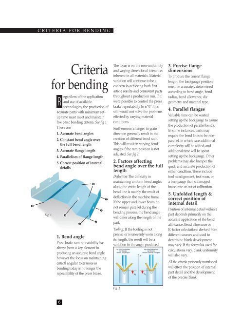
CRITERIA FOR BENDING<br />
1<br />
Fig. 1<br />
Criteria<br />
for bending<br />
R<br />
egardless of the application<br />
and use of available<br />
technologies, the production of<br />
accurate parts with minimum setup<br />
time must meet and maintain<br />
five basic bending criteria. See fig 1.<br />
These are:<br />
1. Accurate bend angles<br />
2. Constant bend angle over<br />
the full bend length<br />
3. Accurate flange length<br />
4. Parallelism of flange length<br />
5. Correct position of internal<br />
details<br />
5<br />
3<br />
1. Bend angle<br />
Press brake ram repeatability has<br />
always been a key element in<br />
producing an accurate bend angle,<br />
however the focus on maintaining<br />
critical angular tolerances in<br />
bending today is no longer the<br />
repeatability of the press brake.<br />
4<br />
2<br />
2<br />
2<br />
The focus is on the non-uniformity<br />
and varying dimensional tolerances<br />
in<strong>here</strong>nt in all materials. Material<br />
variation will continue to be a<br />
concern in achieving both first<br />
article results and consistent parts<br />
throughout a production run. If it<br />
were possible to control the press<br />
brake repeatability to ±"0", this<br />
still would not solve the problems<br />
effected by varying material<br />
conditions.<br />
Furthermore, changes in grain<br />
direction generally result in the<br />
creation of different bend radii.<br />
This will result in varying bend<br />
angles if the ram position is not<br />
adjusted. See fig 2.<br />
2. Factors affecting<br />
bend angle over the full<br />
length<br />
Deflection: The difficulty in<br />
maintaining uniform bend angles<br />
along the entire length of the<br />
bend line is mainly the result of<br />
deflection in the machine frame.<br />
If the upper and lower beam do<br />
not remain parallel during the<br />
bending process, the bend angle<br />
will differ along the length of the<br />
part.<br />
Tooling: If the tooling is not<br />
precise or is unevenly worn along<br />
its length, the result will be a<br />
variation in the angle produced.<br />
low sliding/low hardness<br />
low thickness<br />
direction along the grain<br />
high sliding/high hardness<br />
high thickness<br />
direction transversal to the grain<br />
3. Precise flange<br />
dimensions<br />
To produce the correct flange<br />
length, the backgauge position<br />
must be accurately determined<br />
according to bend angle, bend<br />
radius, bend allowance, die<br />
geometry and material type.<br />
4. Parallel flanges<br />
Valuable time can be wasted<br />
setting up the backgauge to assure<br />
the production of parallel bends.<br />
In some instances, parts may<br />
require the bend lines to be nonparallel,<br />
in which case additional<br />
complexity will be added, and<br />
additional time will be spent<br />
setting up the backgauge. Other<br />
problems may also hamper the<br />
quick and accurate production of<br />
either condition. These include<br />
tool misalignment, tool wear, or<br />
a backgauge that is damaged,<br />
inaccurate or out of calibration.<br />
5. Unfolded length &<br />
correct position of<br />
internal detail<br />
Position of internal detail within a<br />
part depends primarily on the<br />
accurate application of the bend<br />
allowance. Bend allowance or<br />
K-factor calculations derived from<br />
different sources and used to<br />
determine blank development<br />
may vary. If the formulas used for<br />
calculations vary, blank uniformity<br />
will also vary.<br />
All the criteria previously mentioned<br />
will effect the position of internal<br />
part detail and the development<br />
of the precise blank.<br />
Fig. 2<br />
6