Download PDF brochure here - LVD
Download PDF brochure here - LVD
Download PDF brochure here - LVD

Create successful ePaper yourself
Turn your PDF publications into a flip-book with our unique Google optimized e-Paper software.
PRESS BRAKES<br />
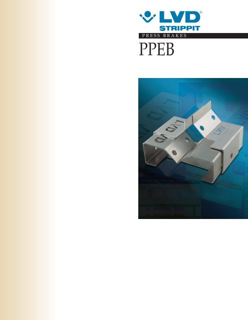
PPEB
THE PPEB SYSTEM<br />
The Ultimate<br />
CNC Hydraulic<br />
Press Brakes<br />
M<br />
eeting the demands of a<br />
constantly changing marketplace<br />
requires flexibility,<br />
reliability and the use of advanced<br />
production techniques that ensure<br />
end-product quality.<br />
Flexible automation has become<br />
a key element in the success of<br />
any manufacturer. <strong>LVD</strong> PPEB<br />
and Easy-Form ® press brakes<br />
represent the latest technology<br />
in press brake automation,<br />
providing industry with the<br />
means to respond to an everevolving<br />
marketplace.<br />
Features such as these help PPEB<br />
and Easy-Form press brakes lead<br />
the way in process automation.<br />
User-friendly PC-based<br />
CNC Control<br />
■ Powerful CADMAN ® Touch<br />
PC-based Windows ® Control<br />
ensures fail-safe operation of<br />
the machine while offering the<br />
operator considerable assistance<br />
in part programming<br />
■ Exclusive CADMAN-B 3D<br />
bending software allows<br />
automatic programming of the<br />
part and precise determination<br />
of the blank size<br />
2
■ Bending sequences are<br />
automatically determined from<br />
the user-drawn 2D part created<br />
with the simple-to-use graphics<br />
editor<br />
■ All axes of the press brake,<br />
including the CNC crowning<br />
system, are calculated by the<br />
control and are automatically<br />
positioned for optimum<br />
bending results<br />
■ 2D & 3D color graphics<br />
simulate part creation and<br />
display material handling<br />
sequencing for optimum part<br />
production<br />
■ Tool libraries and interactive<br />
databases are maintained<br />
automatically for application<br />
of the precise bend allowance<br />
factors and angle correction<br />
values, ensuring accurate first<br />
time bends with minimal or<br />
no trial bending<br />
■ CADMAN ® Touch control<br />
provides the fastest and most<br />
accurate way to produce parts<br />
on a press brake today<br />
■ Graphic interface ensures fast<br />
art to part times<br />
Rigid Frame Design<br />
■ Press brakes up to 400 tons are<br />
designed and built utilizing a<br />
welded one-piece frame,<br />
machined without repositioning,<br />
guaranteeing machine precision<br />
■ Hydraulic cylinders are machined<br />
from a solid steel billet<br />
■ Pistons are steel forgings,<br />
precision ground and<br />
micropolished for years of<br />
trouble-free service<br />
Microprocessor<br />
Technology for<br />
Optimum Precision<br />
■ Servo-controlled using<br />
state-of-the-art hydraulics and<br />
electronics to ensure perfect<br />
control of the bending process<br />
■ Double bed referenced<br />
encoders are connected to<br />
the bed in such a way that<br />
deformation of the side frames<br />
during bending does not<br />
influence the positioning<br />
accuracy of the upper beam<br />
(Y1,Y2)<br />
Easy-Form ® Laser<br />
Measuring System<br />
■ Patented system (EP 1 102 032)<br />
allows exact measurement of<br />
the angle during the bending<br />
process<br />
■ Laser sensing mechanism tracks<br />
the plate during the bending<br />
process and transmits the digital<br />
information in real time to the<br />
CNC control unit<br />
■ CNC unit processes the<br />
information and subsequently<br />
recalculates the depth<br />
adjustment to obtain the<br />
correct angle in real time –<br />
with no process interruption<br />
and no loss of production time<br />
Programmable Crowning<br />
System V-axis<br />
■ CNC crowning ensures the ram<br />
and table are parallel during the<br />
bending operation<br />
■ Sheet thickness, length, die<br />
opening and tensile strength<br />
data are entered into the control<br />
■ Force and related deflection<br />
of the table and ram are<br />
automatically determined,<br />
preloading is optimally<br />
obtained for each bend<br />
With <strong>LVD</strong> PPEB and Easy-Form<br />
press brakes, you obtain an<br />
optimal bending process and<br />
excellent bending results —from<br />
the first piece.<br />
Windows® is a registered trademark of Microsoft Corporation<br />
3
CADMAN ®<br />
TOUCH<br />
CADMAN ®<br />
Touch<br />
Power at your<br />
finger tips<br />
<strong>LVD</strong>’s new generation<br />
CADMAN ® Touch control<br />
employs the latest in infrared<br />
touch screen technology on a<br />
Windows ® embedded PC based<br />
control unit, combining the<br />
power of the CNC control with<br />
the speed and simplicity of touch<br />
screen programming.<br />
Key Features:<br />
Powerful<br />
A multitasking control features on board<br />
integration with <strong>LVD</strong>’s CADMAN-B 3D<br />
offline software, seamlessly linking the<br />
online intelligent bending database with the<br />
offline bending software.<br />
Intuitive<br />
A new user interface minimizes input to the<br />
control.<br />
Fast ‘Art to Part’<br />
CADMAN ® Touch has been designed to<br />
minimize the operator’s input from drawing<br />
to part.<br />
Flexible<br />
2D and 3D files can be input directly at the<br />
machine control, allowing the flexibility to<br />
program parts both on and offline.<br />
Easy to use<br />
CADMAN ® Touch’s intuitive icon driven<br />
interface ensures that operators find using<br />
CADMAN ® Touch easy and productive.<br />
Highly reliable<br />
The infrared touch screen technology used<br />
in the CADMAN ® Touch control is a robust<br />
industrial design, successfully at work in<br />
other <strong>LVD</strong> products.<br />
Network compatible<br />
CADMAN ® Touch is fully network capable,<br />
permitting integration to CADMAN-B 3D<br />
offline and workshop networks for<br />
programming and backup.<br />
Press brakes equipped with the CADMAN ®<br />
Touch control also feature a jog button on<br />
the foot pedal, allowing the operator to ‘jog’<br />
individual axes of the machine for fine<br />
adjustments.<br />
Graphic user interface<br />
Part database<br />
Fast 2D part programming<br />
4<br />
Bending simulation
INTELLIGENT BENDING SOFTWARE<br />
CADMAN ® -B 3D simplifies the<br />
programming of formed parts and<br />
automatically determines the correct<br />
unfolding of the part, the bend<br />
sequence, gauging positions and tool<br />
selection, all optimized for minimum<br />
tool stations and part turns. By utilizing<br />
an “intelligent”database shared with<br />
the press brake, CADMAN-B 3D<br />
ensures that a correct part is achieved<br />
from the first part.<br />
Virtual bending simulation<br />
Parametric tooling<br />
■ Automatically calculates the<br />
optimum bend sequences using<br />
3D data<br />
■ Model matching of imported 2D<br />
unfolded parts based on the bending<br />
technology<br />
■ Automatically calculates the<br />
optimum tool station set-up and<br />
provides a complete graphical report<br />
for the press brake operator<br />
Productview tree<br />
Three point gauge fingers<br />
■ Utilizes a true 3D solid model of<br />
your press brake and all its options<br />
to check interference and collision<br />
between the part, tools and machine<br />
■ Generates a complete 3D bending<br />
simulation, automatically<br />
downloaded to your <strong>LVD</strong> press brake<br />
for easy reference during bending<br />
production<br />
Tool setup<br />
3D view for part & tooling<br />
■ Provides automatic definition of<br />
inclined, parallel and multi-bends<br />
and simplified definition of<br />
hemming bends and preliminary<br />
bends<br />
■ Complete flexibility to manually or<br />
semi-automatically sequence, gauge<br />
and bend parts<br />
Automatic collision detection<br />
3D simulation of hemming bends<br />
5
CRITERIA FOR BENDING<br />
1<br />
Fig. 1<br />
Criteria<br />
for bending<br />
R<br />
egardless of the application<br />
and use of available<br />
technologies, the production of<br />
accurate parts with minimum setup<br />
time must meet and maintain<br />
five basic bending criteria. See fig 1.<br />
These are:<br />
1. Accurate bend angles<br />
2. Constant bend angle over<br />
the full bend length<br />
3. Accurate flange length<br />
4. Parallelism of flange length<br />
5. Correct position of internal<br />
details<br />
5<br />
3<br />
1. Bend angle<br />
Press brake ram repeatability has<br />
always been a key element in<br />
producing an accurate bend angle,<br />
however the focus on maintaining<br />
critical angular tolerances in<br />
bending today is no longer the<br />
repeatability of the press brake.<br />
4<br />
2<br />
2<br />
2<br />
The focus is on the non-uniformity<br />
and varying dimensional tolerances<br />
in<strong>here</strong>nt in all materials. Material<br />
variation will continue to be a<br />
concern in achieving both first<br />
article results and consistent parts<br />
throughout a production run. If it<br />
were possible to control the press<br />
brake repeatability to ±"0", this<br />
still would not solve the problems<br />
effected by varying material<br />
conditions.<br />
Furthermore, changes in grain<br />
direction generally result in the<br />
creation of different bend radii.<br />
This will result in varying bend<br />
angles if the ram position is not<br />
adjusted. See fig 2.<br />
2. Factors affecting<br />
bend angle over the full<br />
length<br />
Deflection: The difficulty in<br />
maintaining uniform bend angles<br />
along the entire length of the<br />
bend line is mainly the result of<br />
deflection in the machine frame.<br />
If the upper and lower beam do<br />
not remain parallel during the<br />
bending process, the bend angle<br />
will differ along the length of the<br />
part.<br />
Tooling: If the tooling is not<br />
precise or is unevenly worn along<br />
its length, the result will be a<br />
variation in the angle produced.<br />
low sliding/low hardness<br />
low thickness<br />
direction along the grain<br />
high sliding/high hardness<br />
high thickness<br />
direction transversal to the grain<br />
3. Precise flange<br />
dimensions<br />
To produce the correct flange<br />
length, the backgauge position<br />
must be accurately determined<br />
according to bend angle, bend<br />
radius, bend allowance, die<br />
geometry and material type.<br />
4. Parallel flanges<br />
Valuable time can be wasted<br />
setting up the backgauge to assure<br />
the production of parallel bends.<br />
In some instances, parts may<br />
require the bend lines to be nonparallel,<br />
in which case additional<br />
complexity will be added, and<br />
additional time will be spent<br />
setting up the backgauge. Other<br />
problems may also hamper the<br />
quick and accurate production of<br />
either condition. These include<br />
tool misalignment, tool wear, or<br />
a backgauge that is damaged,<br />
inaccurate or out of calibration.<br />
5. Unfolded length &<br />
correct position of<br />
internal detail<br />
Position of internal detail within a<br />
part depends primarily on the<br />
accurate application of the bend<br />
allowance. Bend allowance or<br />
K-factor calculations derived from<br />
different sources and used to<br />
determine blank development<br />
may vary. If the formulas used for<br />
calculations vary, blank uniformity<br />
will also vary.<br />
All the criteria previously mentioned<br />
will effect the position of internal<br />
part detail and the development<br />
of the precise blank.<br />
Fig. 2<br />
6
<strong>LVD</strong> SOLUTIONS<br />
<strong>LVD</strong> Solutions<br />
T<br />
hese features of <strong>LVD</strong> press<br />
brake technology address the<br />
problems of bending and<br />
ensure the quality of every end<br />
product produced.<br />
1. Bend Angle<br />
Precision Engineering: The <strong>LVD</strong><br />
PPEB precision hydraulic press<br />
brakes are designed by "finite<br />
elements analysis." All models are<br />
equipped with bed-referenced<br />
linear encoders and the latest<br />
servo-controlled hydraulic<br />
systems to ensure precise control<br />
of the upper beam position and<br />
repeatability.<br />
170<br />
CADMAN ® Control/Software:<br />
The <strong>LVD</strong> CADMAN ® Touch press<br />
brake control assures first time<br />
bend angle results by the automatic<br />
application of the exclusive<br />
CADMAN angle correction<br />
database. Previous bending data<br />
experience on specific tools and<br />
materials are cross-referenced and<br />
automatically applied.<br />
Easy-Form ® Laser: The patented<br />
Easy-Form Laser angle control<br />
system controls the bend angle in<br />
real time without slowing the<br />
bending process.<br />
2. Factors affecting bend<br />
angle over full length<br />
Deflection compensation<br />
system, V-Axis: The <strong>LVD</strong> CNC<br />
two-piece wedge deflection<br />
compensation system corrects<br />
the non-parallel condition of<br />
the bed/ram relationship<br />
created by deflection of the<br />
machine during bending.<br />
See fig 3.<br />
Tooling: <strong>LVD</strong> precision-ground<br />
tooling, with the patented STONE ®<br />
radius, assures accurate bend<br />
angles along the entire bending<br />
length. STONE tooling is produced<br />
with a progressive radius on both<br />
sides of the V-opening, allowing<br />
the material to flow into the die<br />
more evenly and with less drag.<br />
This unique design of the V-die<br />
reduces the friction between the<br />
material and the die encountered<br />
when bending, by creating a<br />
rolling condition as the material<br />
enters the die. See fig 4a & b.<br />
STONE ® tooling also provides:<br />
• Reduced tool wear<br />
• Tool interchangeability<br />
• Reduced residue on<br />
stainless steel<br />
• Improved material control<br />
• Reduced tonnage requirements<br />
• Symmetric bending<br />
Fig. 4a. Normal radius<br />
Progressive radius<br />
% of slipping / rolling<br />
Bend angle<br />
% of slipping / rolling<br />
Bend angle<br />
Fig. 3<br />
Fig. 4b. STONE radius<br />
7
<strong>LVD</strong> SOLUTIONS<br />
3. Precise flange dimensions<br />
Intelligent database: <strong>LVD</strong> uses<br />
this method to obtain the correct<br />
position of the backgauge (with<br />
consideration for the bend<br />
allowance).<br />
A piece of known data (e.g. .059"<br />
mild steel, 4" x 4") is entered onto a<br />
setup page on the control. See fig 5a.<br />
After performing a 90-degree bend,<br />
the control requests the following<br />
information: length of leg 1, length<br />
of leg 2. This information is then<br />
stored in a database. See fig 5b.<br />
When programming parts of the<br />
same material and tooling parameters,<br />
the database information is<br />
automatically used to give precise<br />
flange lengths the first time. This<br />
is possible because the database<br />
Fig. 5a<br />
contains actual proven values and<br />
not theoretical values. <strong>LVD</strong> has<br />
performed tests on various types<br />
and thicknesses of material, using<br />
different V-dies.<br />
This intelligent database which is<br />
preloaded on all machines<br />
together with a tooling library,<br />
can be extended with actual<br />
bending results.<br />
4. Parallel and nonparallel<br />
flanges<br />
Tool alignment: The <strong>LVD</strong> design<br />
assures precision alignment of the<br />
upper punch and lower V-die,<br />
allowing quick set-up and<br />
changeover time.<br />
The latest technology AC drives<br />
and encoders are used to ensure<br />
the highest possible accuracy and<br />
repeatability.<br />
Backgauge accuracy: <strong>LVD</strong><br />
backgauge systems offer the<br />
ultimate in flexibility in the<br />
production of both parallel and<br />
non-parallel flanges. The unique<br />
three-point gauge fingers allow<br />
automatic calculation and setting<br />
of both the backgauge and side<br />
stop positions for accurate part<br />
production. See fig 6.<br />
5. Unfolded length and<br />
correct position of internal<br />
detail<br />
<strong>LVD</strong>’s CADMAN software:<br />
Automatically applies information<br />
from the bend allowance<br />
database, making it possible for<br />
the user to determine exact<br />
positions of internal details and<br />
the correct dimensions for the<br />
undeveloped blank.<br />
Having proven data from the<br />
press brake in advance of blank<br />
production means no alterations<br />
are necessary to the part throughout<br />
its production. Accurate blank<br />
development, laser or punch press<br />
processing and bending are<br />
assured by using proven data<br />
provided by the CADMAN<br />
software. See fig 7.<br />
Fig. 7<br />
Fig. 5b<br />
Fig. 6 Three-point gauge fingers<br />
8
EASY-FORM ®<br />
LASER<br />
Easy-Form ®<br />
Laser<br />
Typical problems:<br />
• High scrap rates<br />
• Small batches<br />
• Material variation<br />
• Thickness variations<br />
• Constant need for angle<br />
corrections<br />
Fig. 8a<br />
<strong>LVD</strong>’s solution<br />
The patented Easy-Form ® Laser<br />
angle measuring system controls<br />
the bend angle in real time without<br />
slowing the bending process.<br />
See fig 8a & b.<br />
The unique design of the<br />
Easy-Form system allows the<br />
machine to adapt to variation<br />
in material consistency and<br />
compensates for any changes<br />
in radius as a result of grain<br />
direction changes.<br />
See fig 8c.<br />
Fig. 8c<br />
Fig. 8d<br />
First time bend angles and<br />
consistent part repeatability are<br />
assured. See fig 8d.<br />
The Easy-Form Laser system<br />
guarantees the desired angle<br />
from the first bending operation.<br />
The angle measuring system,<br />
located on the front and back side<br />
of the press brake table, consists<br />
of two laser monitors linked with<br />
an intelligent bending database in<br />
the CADMAN ® Touch control. As<br />
the bending sequence of the press<br />
brake is initiated, the sensing<br />
device transmits the digital<br />
information in real time to the<br />
CNC control unit, which processes<br />
it and subsequently recalculates<br />
the correct depth adjustment to<br />
obtain the correct angle. The<br />
bending process is not interrupted,<br />
and no production time is lost.<br />
Independent of<br />
Measuring Device<br />
Distance<br />
Fig. 8b<br />
Independent of<br />
Die Orientation<br />
Independent of<br />
Off-center Bending<br />
Conditions<br />
9
BACKGAUGES<br />
Whether you require a basic twoaxis<br />
backgauge or a more complex<br />
system to allow multi-bend set-ups<br />
and the production of taper bends,<br />
<strong>LVD</strong> can offer a solution that takes<br />
the guess work out of all axis<br />
position calculations by using the<br />
CADMAN advanced software.<br />
Five-axis backgauge X-R-Z1-Z2-X'<br />
Six-axis backgauge X1R1Z1-X2R2Z2<br />
PPEB-EQ PPEB-5 PPEB-8 PPEB-EFL PPEB-H<br />
X-R-Z1-Z2<br />
●<br />
X-R<br />
●<br />
X-R-Z1-Z2-X' ● ●<br />
Modules X1R1-X2R2 ❍<br />
X1R1Z1-X2R2Z2 ❍ ❍ ❍<br />
● Standard up to 400 T<br />
❍ Optional<br />
10
Two-axis backgauge (X-R) with manual Z-axis.<br />
Pneumatic clamping for finger positioning on PPEB-5<br />
Five-axis backgauge X-R-Z1-Z2-X’ on PPEB-8 and PPEB-EFL<br />
Six-axis modular backgauge X1R1Z1-X2R2Z2 up to 400T<br />
PP8250 - X = 23.6” (600 mm), PP8251 - X = 39.3” (1000 mm)<br />
Six-axis modular backgauge X1R1Z1-X2R2Z2 for 500T & 640T<br />
X = 47.2” (1200 mm), R = 11.3” (300 mm)<br />
15.7” (400 mm)<br />
Standard PPEB backgauge with<br />
three gauge positions allows<br />
gauging to 39.3” (1000 mm)<br />
with material support<br />
Standard eight-axis three-point<br />
gauging finger PPEB-8<br />
1.96”<br />
(50 mm)<br />
1.96”<br />
(50 mm)<br />
3.85”<br />
(98 mm)<br />
1.37”<br />
(35 mm)<br />
19.6” (500 mm)<br />
on 500T & 640T<br />
Standard backgauge<br />
finger PPEB-5<br />
3.93”<br />
(100 mm)<br />
0.29” (7,5 mm)<br />
1.96”<br />
(50 mm)<br />
11
OPTIONS<br />
Features Designed for Productivity<br />
Quick set-up time<br />
■ Quick-acting manual or hydraulic clamping<br />
■ Vertical removable self-seated tooling<br />
■ Precision hardened and ground tooling<br />
■ In process angle measurement<br />
Hydraulic clamping system on table PP3160<br />
Self-seating manual clamping system PP3090<br />
Self-seating hydraulic clamping system PP3100<br />
Easy-Form ® Laser 90<br />
Easy-Form ® Laser 130<br />
Easy-Form ® Laser 200
Safety<br />
& Increased Productivity<br />
■ Safe operation<br />
■ Programmable tooling<br />
■ Front sheet supports<br />
■ CNC controlled sheet followers<br />
PP5320 Lazer Safe protection<br />
PP3000 Hemming table in combination with EFL90<br />
PP1115 Front sheet supports<br />
PP8402 T1, T2 CNC sheet supports with CNC<br />
vertical adjustment / Standard duty<br />
PP8402 Heavy duty
TECHNICAL SPECIFICATIONS<br />
Technical Specifications<br />
PPEB<br />
Type 80/15 80/20 80/25 80/30 80/Turbo 110/30 110/40<br />
Pressing force ton 90 90 90 90 90 120 120<br />
Working length inch A 59 78 98 120 120 157<br />
Distance between uprights inch B 41 61 80 102 102 124<br />
Stroke inch C 7.9 7.9 7.9 7.9 7.9 7.9<br />
Distance table/ram inch E 15.7 15.7 15.7 15.7 15.7 15.7<br />
Gap inch D 15.7 15.7 15.7 15.7 15.7 15.7<br />
Table width inch F 4.7 4.7 4.7 4.7 4.7 4.7<br />
Approach speed* inch/min 307 307 307 307 378 307 307<br />
Working speed** inch/min 24 24 24 26 52 28 28<br />
Return speed inch/min 272 272 272 272 472 272 272<br />
Motor HP 12 12 12 12 24 24 24<br />
Oil Gal 33 33 33 33 66 66<br />
Type 220/30 220/30 Plus 220/40 220/40 Plus 220/42 220/42 Plus 220/50 220/50 Plus 220/61<br />
Pressing force ton 240 240 240 240 240 240 240 240 240<br />
Working length inch A 120 120 157 157 168 168 196 196 240<br />
Distance between uprights inch B 102 102 124 124 150 150 179 179 198<br />
Stroke inch C 7.9 11.8 7.9 11.8 7.9 11.8 7.9 11.8 7.9<br />
Distance table/ram inch E 15.7 22.4 15.7 22.4 15.7 22.4 15.7 22.4 15.7<br />
Gap inch D 15.7 15.7 15.7 15.7 15.7 15.7 15.7 15.7 15.7<br />
Table width inch F 4.7 4.7 4.7 4.7 4.7 4.7 4.7 4.7 4.7<br />
Approach speed* inch/min 283 283 283 283 283 283 283 283 283<br />
Working speed** inch/min 50 50 50 50 50 50 50 50 50<br />
Return speed inch/min 472 472 472 472 472 472 472 472 472<br />
Motor HP 60 60 60 60 60 60 60 60 60<br />
Oil Gal 92 92 92 92 92 92 92 92 92<br />
* For CE-countries only if the machine is equipped with an optional safety system<br />
** For CE-countries working speed is limited to safety norm<br />
General specifications subject to change without notice.<br />
Different combinations of stroke and daylight are available in our standard range by increments of +3.93”(100 mm).<br />
14
110/42 110/Turbo 135/30 135/40 135/42 135/Turbo 170/30 170/40 170/42 170/50 170/Turbo<br />
120 120 150 150 150 150 190 190 190 190 190<br />
168 120 157 168 120 157 168 196<br />
150 102 124 150 102 124 150 179<br />
7.9 7.9 7.9 7.9 7.9 7.9 7.9 7.9<br />
15.7 15.7 15.7 15.7 15.7 15.7 15.7 15.7<br />
15.7 15.7 15.7 15.7 15.7 15.7 15.7 15.7<br />
4.7 4.7 4.7 4.7 4.7 4.7 4.7 4.7<br />
307 425 307 307 307 425 236 236 236 236 425<br />
28 52 28 28 28 52 28 28 28 28 52<br />
272 472 272 272 272 472 307 307 307 307 472<br />
24 35 24 24 24 35 35 35 35 35 60<br />
66 66 66 66 92 92 92 92<br />
220/61 Plus 320/30 320/40 320/45 320/61 400/40 400/45 400/61 500/40 500/45 500/61 640/45 640/61 640/81<br />
240 350 350 350 350 440 440 440 550 550 550 700 700 700<br />
240 120 157 177 240 160 177 240 160 177 240 177 240 315<br />
198 102 124 150 198 124 150 198 124 148 198 148 198 277<br />
11.8 11.8 11.8 11.8 11.8 11.8 11.8 11.8 11.8 11.8 11.8 11.8 11.8 11.8<br />
22.4 22.4 22.4 22.4 22.4 22.4 22.4 22.4 22.4 22.4 22.4 22.4 22.4 22.4<br />
15.7 15.7 15.7 15.7 15.7 15.7 15.7 15.7 15.7 15.7 15.7 15.7 15.7 15.7<br />
4.7 7.9 7.9 7.9 7.9 7.9 7.9 7.9 7.9 7.9 7.9 7.9 7.9 7.9<br />
283 283 283 283 283 236 236 236 236 236 236 212 212 212<br />
50 33 33 33 33 26 26 26 21 21 21 21 21 21<br />
472 307 307 307 307 283 283 283 189 189 189 236 236 236<br />
60 60 60 60 60 60 60 60 60 60 60 90 90 90<br />
92 106 106 106 106 132 132 132 185 185 185 225 225 225<br />
15
CONFIGURATIONS<br />
Custom-Made Machines<br />
Features<br />
■ Increased daylight<br />
■ Increased stroke<br />
■ Increased throat gap<br />
■ Automatic tool changing<br />
■ Automated material handling<br />
■ Programmable tooling<br />
Tandem Operation<br />
■ Synchronized operation of two<br />
machines with single CNC control<br />
■ Independent operation of each<br />
machine with separate control<br />
■ Dissimilar tonnage and lengths in<br />
tandem<br />
■ CNC deflection compensation<br />
Easy-Form 220/35 and PPEB 220/35 in tandem<br />
PPEB 640T<br />
Special tooling application<br />
16
HEAVY DUTY APPLICATIONS<br />
PPEB 2000/140<br />
Special tooling<br />
PPEB 1500/100 and PPEB 800/60 in tandem<br />
PPEB 1000/50<br />
17
TYPICAL HEAVY<br />
DUTY APPLICATIONS<br />
When it comes to heavy<br />
bending applications, <strong>LVD</strong><br />
has the custom solution for:<br />
■ Earth moving equipment<br />
■Yellow goods<br />
■ Lighting poles<br />
■ Transportation<br />
■ Defense / Aerospace / Marine<br />
■ Industrial and commercial machinery
TECHNICAL<br />
SPECIFICATIONS<br />
Technical Specifications<br />
PPEB-H<br />
Type 800/45 800/61 800/80 1000/61 1000/80 1000/100 1000/120<br />
Pressing force ton 880 880 880 1100 1100 1100 1100<br />
Working length inch A 177 240 315 240 218 293 472<br />
Distance between uprights inch B 148 198 277 198 277 316 356<br />
Stroke inch C 23.6 23.6 23.6 23.6 23.6 23.6 23.6<br />
Distance table/ram inch E 34.3 34.3 34.3 34.3 34.3 34.3 34.3<br />
Gap inch D 15.7 15.7 15.7 15.7 15.7 15.7 15.7<br />
Table width inch F 11.8 11.8 11.8 11.8 11.8 11.8 11.8<br />
Approach speed* inch/min 236 236 236 212 212 212 212<br />
Working speed** inch/min 24 24 24 21 21 21 21<br />
Return speed inch/min 236 236 236 212 212 212 212<br />
Motor HP 145 145 145 145 145 145 145<br />
Oil Gal 396 396 396 396 396 396 396<br />
Type 1250/61 1250/80 1250/100 1250/120 1600/80 1600/120 2000/140 3000/150<br />
Pressing force ton 1375 1375 1375 1375 1760 2200 3300<br />
Working length inch A 240 318 393 472 315 472 551 590<br />
Distance between uprights inch B 198 277 316 356 258 356 490 472<br />
Stroke inch C 23.6 23.6 23.6 23.6 23.6 23.6 35.4 31.5<br />
Distance table/ram inch E 34.3 34.3 34.3 34.3 39.4 39.4 63.0 78.8<br />
Gap inch D 19.7 19.7 19.7 19.7 23.6 23.6 49.2 33.5<br />
Table width inch F 11.8 11.8 11.8 11.8 19.7 19.7 31.5 35.4<br />
Approach speed* inch/min 189 189 189 189 142 142 182 165<br />
Working speed** inch/min 16 16 16 16 16 16 21 14<br />
Return speed inch/min 200 200 200 200 170 170 200 130<br />
Motor HP 145 145 145 145 2x90 2x90 2x120 2x120<br />
Oil Gal 396 396 396 396 476 476 792 925<br />
* For CE-countries only if the machine is equipped with an optional safety system<br />
** For CE-countries working speed is limited to safety norm<br />
Upon request, other specifications are also available.<br />
General specifications subject to change without notice.<br />
19
A D D R E S S E S<br />
HEADQUARTERS<br />
Strippit Inc.<br />
12975 Clarence Center Rd.<br />
USA-AKRON NY 14001<br />
UNITED STATES<br />
Tel. + 1 716 5424511<br />
Fax + 1 716 5425957<br />
e-mail: info@strippit.com<br />
<strong>LVD</strong> Company nv<br />
Nijverheidslaan 2<br />
B-8560 GULLEGEM<br />
BELGIUM<br />
Tel. + 32 56 43 05 11<br />
Fax + 32 56 43 25 00<br />
e-mail: info@lvd.be<br />
JOINT VENTURES<br />
<strong>LVD</strong>-HD<br />
Huangshi City,<br />
Hubei Province, China<br />
SUBSIDIARIES*<br />
<strong>LVD</strong> BeNeLux nv<br />
Gullegem, Belgium<br />
<strong>LVD</strong> GmbH<br />
Lahr, Germany<br />
<strong>LVD</strong> s.a.<br />
Raismes, France<br />
<strong>LVD</strong> Italia s.r.l.<br />
Parma, Italy<br />
<strong>LVD</strong> Limited<br />
Oxfordshire, United Kingdom<br />
<strong>LVD</strong> SWE-NOR A/S<br />
Oslo, Norway<br />
<strong>LVD</strong> GR E.P.E.<br />
Volos, Greece<br />
<strong>LVD</strong>-Polska Sp. z.o.o.<br />
Kedzierzyn-Kozle, Poland<br />
<strong>LVD</strong> SIT d.o.o.<br />
Ajdovscina, Slovenia<br />
<strong>LVD</strong> S 2 =<br />
Tornala, Slovakia<br />
<strong>LVD</strong> Napomar s.a.<br />
Cluj, Romania<br />
<strong>LVD</strong> do Brasil Ltda.<br />
Joinville, Brazil<br />
Magal <strong>LVD</strong> India Pvt. Ltd.<br />
Bangalore, India<br />
P.T. <strong>LVD</strong> Center<br />
Jakarta, Indonesia<br />
<strong>LVD</strong> (Malaysia) Sdn. Bhd<br />
Shah Alam, Malaysia<br />
<strong>LVD</strong> Company Ltd.<br />
Bangkok, Thailand<br />
<strong>LVD</strong>-Strippit (Shanghai) Co., Ltd.<br />
Shanghai, China<br />
* For full address details of your local<br />
subsidiary or agent, or to download the<br />
latest literature, please visit our website:<br />
www.lvdgroup.com<br />
01.2011 PPEB 2.000 ENG Subject to alterations