Computational study of sludge pump design with vortex impeller
Computational study of sludge pump design with vortex impeller
Computational study of sludge pump design with vortex impeller

Create successful ePaper yourself
Turn your PDF publications into a flip-book with our unique Google optimized e-Paper software.
. 18<br />
m 2012<br />
th International Conference<br />
ENGINEERING MECHANICS 2012 pp. 191–201<br />
Svratka, Czech Republic, May 14 – 17, 2012 Paper #87<br />
COMPUTATIONAL STUDY OF SLUDGE PUMP DESIGN WITH<br />
VORTEX IMPELLER<br />
M. !ervinka *<br />
Abstract: This paper presents a computational <strong>study</strong> <strong>of</strong> <strong>sludge</strong> <strong>pump</strong> <strong>design</strong> <strong>with</strong> <strong>vortex</strong> <strong>impeller</strong>. It<br />
contains two <strong>design</strong> variants <strong>of</strong> <strong>vortex</strong> <strong>impeller</strong>, which is supported by CFD calculations in ANSYS<br />
Fluent. By modeling the problem in Fluent, it has been verified that such <strong>impeller</strong>s could be fitted into the<br />
existing spiral casing <strong>with</strong> channel <strong>impeller</strong>. It was verified that the original operating parameters were<br />
maintained. Results <strong>of</strong> these <strong>design</strong> solutions and evaluation <strong>of</strong> effect <strong>of</strong> some construction modifications<br />
on the <strong>pump</strong> characteristics have been shown.<br />
Keywords: Sludge <strong>pump</strong>, <strong>vortex</strong> <strong>impeller</strong>, characteristics, <strong>design</strong>, <strong>Computational</strong> Fluid Dynamic.<br />
1. Introduction<br />
Sludge <strong>pump</strong>s are used in many different branches <strong>of</strong> industry. We can find them in wastewater<br />
treatment plants, industry, home, etc. These <strong>pump</strong>s are very <strong>of</strong>ten used for polluted water <strong>pump</strong>ing<br />
<strong>with</strong> abrasive particles. For this reason, these <strong>pump</strong>s can differ in construction, shape or used materials<br />
from classical hydrodynamic <strong>pump</strong>s. This paper describes a <strong>design</strong> <strong>of</strong> <strong>vortex</strong> <strong>impeller</strong> which can be<br />
fitted into existing spiral casing <strong>of</strong> original <strong>sludge</strong> <strong>pump</strong> <strong>with</strong> channel <strong>impeller</strong>. In the following<br />
chapters, this <strong>design</strong> will be introduced. It was proposed using the original operating parameters and<br />
the <strong>impeller</strong> is based on the principle <strong>of</strong> <strong>vortex</strong> <strong>impeller</strong> <strong>with</strong> commercial name TURO. These<br />
<strong>impeller</strong>s are patented by Swiss company Egger. The second <strong>design</strong> variant <strong>of</strong> <strong>impeller</strong> is based on the<br />
<strong>vortex</strong> <strong>impeller</strong> which is called SuperVortex and is made by Danish company Grunfos. Models were<br />
created for both <strong>impeller</strong>s and the CFD (<strong>Computational</strong> Fluid Dynamic) computations for both <strong>design</strong><br />
variants were made to assess suitability <strong>of</strong> use. For solution and subsequent evaluation <strong>of</strong> this problem<br />
we used the values obtained from CFD calculations.<br />
2. TURO <strong>impeller</strong><br />
The Turo <strong>impeller</strong> has lots <strong>of</strong> advantages. First, it is placed in a different position compared to the<br />
channel <strong>impeller</strong>s; thus the large <strong>vortex</strong> under <strong>impeller</strong> is created. These <strong>impeller</strong>s are used to <strong>pump</strong><br />
polluted water <strong>with</strong> high content <strong>of</strong> abrasive particles therefore only approximately 15% <strong>of</strong> impurities<br />
get into contact <strong>with</strong> the <strong>impeller</strong>. For this reason there is less danger <strong>of</strong> abrasive wear than <strong>with</strong><br />
classical channel <strong>impeller</strong>s. Next advantage is that these <strong>impeller</strong>s usually have a stable characteristic<br />
and in most cases only very low radial force acts on the <strong>impeller</strong>. Another advantage is a very simple<br />
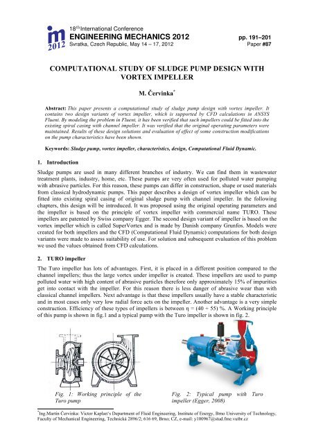
construction. Efficiency <strong>of</strong> these types <strong>of</strong> <strong>impeller</strong>s is between ! = (40 ÷ 55) %. A Working principle<br />
<strong>of</strong> this <strong>pump</strong> is shown in fig.1 and a typical <strong>pump</strong> <strong>with</strong> the Turo <strong>impeller</strong> is shown in fig. 2.<br />
Fig. 1: Working principle <strong>of</strong> the<br />
Turo <strong>pump</strong><br />
Fig. 2: Typical <strong>pump</strong> <strong>with</strong> Turo<br />
<strong>impeller</strong> (Egger, 2008)<br />
* Ing.Martin "ervinka: Victor Kaplan‘s Department <strong>of</strong> Fluid Engineering, Institute <strong>of</strong> Energy, Brno University <strong>of</strong> Technology,<br />
Faculty <strong>of</strong> Mechanical Engineering, Technická 2896/2; 616 69, Brno; CZ, e-mail: y100967@stud.fme.vutbr.cz
192 Engineering Mechanics 2012, #87<br />
3. Design <strong>of</strong> <strong>impeller</strong>s<br />
As mentioned above two models <strong>of</strong> <strong>impeller</strong>s were created. At first the Turo <strong>impeller</strong> model was<br />
created. Basic equations described in (Feranec, 200) were used to <strong>design</strong> this <strong>impeller</strong>. Original<br />
parameters <strong>of</strong> the <strong>pump</strong> are shown in Tab. 1. These parameters and known dimensions <strong>of</strong> spiral casing<br />
were used and main dimensions <strong>of</strong> Turo <strong>impeller</strong> were <strong>design</strong>ed. The model <strong>of</strong> Turo <strong>impeller</strong> can be<br />
seen in fig. 3. Secondly, the other <strong>impeller</strong> model was created by cranking the vanes from the Turo<br />
<strong>impeller</strong> and by creating the so called spur. For this reason this <strong>impeller</strong> will be called “Turo <strong>with</strong><br />
spur” and it can be seen in fig. 4.<br />
3.1. Main dimensions <strong>of</strong> <strong>impeller</strong><br />
According to basic equations, main dimensions were created. In the following chapter, basic equations<br />
and calculated main dimensions can be seen.<br />
Tab. 1: Original operating parameters.<br />
Title Sign Value Unit<br />
Flow rate Q 35.8 [ l/s ]<br />
Head H 21.5 [ m ]<br />
Density # 1050 [ kg/m 3 ]<br />
Speed n 1450 [1/min]<br />
Power P 15 [ kW ]<br />
Number <strong>of</strong> blades z 8 [ - ]<br />
Inlet, outlet angle <strong>of</strong> blade $ 1 , $ 2 90 [ ° ]<br />
Diameter <strong>of</strong> <strong>impeller</strong> D 2<br />
!= g.H<br />
u 2<br />
2<br />
2<br />
u 2 2 = 2.g.H<br />
!<br />
= 2.g.H<br />
u 2<br />
2 (1)<br />
(2)<br />
u 2 =<br />
2.g.H<br />
!<br />
(3)<br />
u 2 =2!n.R 2 = 2.g.<br />
H<br />
!<br />
(4)<br />
D 2 =84,8. 1 n .<br />
H<br />
! =84,8. 1<br />
1450 . 21,5<br />
1,17 =!0, 2507 m (5)<br />
According to equations (1) – (4), we can obtain a final equation (5) for the <strong>impeller</strong> diameter. Based<br />
on this the value <strong>of</strong> diameter was chosen as D 2 = 0,25 m
Červinka M. 193<br />
Impeller width b 2<br />
b 4<br />
b 2<br />
!3 (6)<br />
Or by other equation<br />
b 2 = b 4<br />
3 = 0,08<br />
3 = 0,026666 =>!0,027 m (7)<br />
b 2 = 0,25÷0,3 .D s =!0,3.0,126!= 0,0378 m (8)<br />
From results <strong>of</strong> equations (7) and (8), the value <strong>of</strong> <strong>impeller</strong> width was chosen as b 2 = 0,03 m.<br />
Fig. 3: The Turo <strong>impeller</strong> model<br />
Fig. 4: The Turo <strong>with</strong> spur <strong>impeller</strong> model<br />
3.2. Design <strong>of</strong> CFD model<br />
Geometrical models <strong>of</strong> both <strong>impeller</strong>s were created in Gambit 2.4.6. The computational mesh<br />
contained approximately 6 million hexahedral cells; the worst cell had skewness equal to 0. 7711. The<br />
whole model was split into 5 volumes: <strong>impeller</strong>, space above <strong>impeller</strong>, spiral casing, suction and<br />
displacement. The computation was done in ANSYS Fluent 12. 1 and 2 equation k- % viscosity model<br />
<strong>with</strong> non – equilibrium wall function was used. A steady calculation <strong>with</strong> second order upwind was<br />
performed. To create all <strong>of</strong> these characteristics, an overall range <strong>of</strong> flow rate must be taken into<br />
account. Following <strong>design</strong> points were computed : 1,25* Q N (45 l.s -1 ); Q N (36 l.s -1 ); 0,75* Q N (27 l.s -1 );<br />
0,5* Q N (18 l.s -1 ); 0,25* Q N (9 l.s -1 ) and finally, last point 0,1* Q N (3,6 l.s -1 ) for better projection <strong>of</strong><br />
characteristics at low flow rate was added.<br />
4. Evaluation<br />
4.1. Characteristics <strong>of</strong> <strong>pump</strong><br />
A focus was put on the following characteristics Y – Q, ! – Q, P – Q. As stated in (Pochyl& et. al.,<br />
2009), the Y – Q characteristic should be considered as stable if the following condition <strong>of</strong> stability is<br />
fulfilled across the whole range <strong>of</strong> the flow rate:<br />
!Y<br />
!Q
194 Engineering Mechanics 2012, #87<br />
The characteristics <strong>of</strong> <strong>pump</strong> <strong>with</strong> Turo <strong>with</strong> spur <strong>impeller</strong> are in principle the same as Turo. In fig. 5<br />
the relation between specific energy and flow rate can be seen. It is as stable as the Turo <strong>impeller</strong><br />
characteristic but the decrease <strong>of</strong> specific energy and related head can be seen. At the <strong>design</strong> optimum<br />
for Turo <strong>with</strong> spur <strong>impeller</strong> we obtained head H = 20, 47 m, power P = 12843 W and efficiency ! =<br />
56, 1%, i.e. a decrease compared to the original operating parameters. The difference <strong>of</strong> specific<br />
energy between the <strong>design</strong> variants is shown in fig. 8.<br />
Fig. 5: Y – Q characteristics for both <strong>design</strong><br />
variants<br />
Fig. 6: P – Q characteristics for both <strong>design</strong><br />
variants<br />
Fig. 7: ! – Q characteristics for both <strong>design</strong><br />
variants<br />
Fig. 8: The difference <strong>of</strong> specific energy<br />
between Turo and Turo <strong>with</strong> spur <strong>impeller</strong>s<br />
4.2. Specific energy in different volumes <strong>of</strong> <strong>pump</strong><br />
The characteristics <strong>of</strong> specific energy in dependence on flow rate for different volumes, as introduced<br />
in chapter 3.2, are shown in fig. 9 – 12. The characteristics for the Turo <strong>impeller</strong> are shown in fig. 9,<br />
10 and for the Turo <strong>with</strong> spur are in fig. 11, 12. For both <strong>impeller</strong> volumes, characteristics are unstable<br />
at a low flow rates, which has a negative impact on total characteristics although they are considered<br />
as stable. Both variants have similar shapes <strong>of</strong> these characteristics for the same volumes.
Červinka M. 195<br />
Fig. 9: Y – Q characteristics in specific<br />
volumes for Turo <strong>impeller</strong><br />
Fig. 10: Y – Q characteristics in specific volumes<br />
for Turo <strong>impeller</strong><br />
Fig. 11: Y – Q characteristics in specific volumes<br />
for Turo <strong>with</strong> spur <strong>impeller</strong><br />
Fig. 12: Y – Q characteristics in specific<br />
volumes for Turo <strong>with</strong> spur <strong>impeller</strong><br />
4.3. Axial force<br />
The axial force applied to <strong>impeller</strong>s was obtained, like other values, from CFD computation. The axial<br />
force applied on <strong>impeller</strong>s is shown in fig. 13 and the axial force applied only on <strong>impeller</strong> vanes for<br />
both <strong>design</strong> variants is shown in fig. 14. The axial force is oriented in positive direction <strong>of</strong> z – axis, i.e.<br />
it is negative values are directed into the <strong>impeller</strong> and the shaft is subjected to a compressive stress.<br />
Values <strong>of</strong> axial force for the Turo <strong>with</strong> spur are approximately three times larger than for the Turo.<br />
This is probably due to larger vanes <strong>of</strong> the Turo <strong>with</strong> spur; therefore fluid can act on the <strong>impeller</strong> by<br />
larger force. The axial force is not large for this type <strong>of</strong> <strong>pump</strong>; however it can be lowered by using<br />
construction adjustment stated in (Gan'o, 1999). The best solution for these <strong>impeller</strong>s is compensatory<br />
vanes at the back <strong>of</strong> supporting disk; these vanes can help to minimalize the effect <strong>of</strong> axial force.
196 Engineering Mechanics 2012, #87<br />
Fig. 13: Axial force on <strong>impeller</strong>s<br />
Fig. 14: Axial force on <strong>impeller</strong> vanes<br />
4.4. Influence <strong>of</strong> construction modification<br />
The influence <strong>of</strong> construction modification on <strong>pump</strong> characteristics was examined in this chapter.<br />
Three solutions <strong>of</strong> gap between the <strong>pump</strong> casing and the <strong>impeller</strong> were created. First solution was a<br />
conical gap <strong>with</strong> angle 15°, then a very small cylindrical gap, which was almost like wall behind the<br />
<strong>impeller</strong> and the last solution was a large cylindrical gap between these parts. For better illustration,<br />
these gaps are shown in fig. 15. The results from computation and evaluation <strong>of</strong> influence <strong>of</strong> each<br />
<strong>design</strong> variant are also shown. After obtaining results from CFD computation, we created all <strong>pump</strong><br />
characteristics, which are shown in fig. 16, 17 and 18. The first solution (conical gap) shows the best<br />
results. The second solution (very small gap) has unstable Y – Q characteristic and the efficiency is<br />
lower than for conical gap. The large cylindrical gap has quite similar characteristics as a very small<br />
cylindrical gap. According to results presented in this chapter, it can be said that the conical gap <strong>with</strong><br />
15° angle achieved the best results and shapes <strong>of</strong> characteristics. The computation was made only for<br />
the Turo <strong>impeller</strong>.<br />
Fig. 15: Types <strong>of</strong> gaps a) Conical gap; b) Very small cylindrical gap; c) Large cylindrical gap
Červinka M. 197<br />
Fig. 16: Y - Q characteristics for different types <strong>of</strong> gaps<br />
Fig. 17: P - Q characteristics for different types <strong>of</strong> gaps<br />
Fig. 18: ! – Q characteristics for different types <strong>of</strong> gaps
198 Engineering Mechanics 2012, #87<br />
4.5. Rotational motion in <strong>pump</strong><br />
The model <strong>of</strong> the whole <strong>pump</strong> is quite extensive and it is hard to show the behavior <strong>of</strong> fluid in each<br />
part. Velocity vectors and differences between <strong>design</strong> variants <strong>of</strong> <strong>impeller</strong> are shown. The graphic<br />
interpretation gives us a possibility to show vortices occurring in our model space, fluid behavior, etc.<br />
4.5. 1 Turo <strong>impeller</strong><br />
The main focus was put on fluid behavior in the inter vane channel. Velocity vectors are displayed in<br />
created cuts, which are shown in fig. 19. Velocity vectors in the <strong>impeller</strong> space are shown in fig. 20 –<br />
23. Firstly, we considered an inlet to the <strong>impeller</strong> as it is whole upper face but the figures below show<br />
that the fluid began to leave the <strong>impeller</strong> in the region <strong>of</strong> larger radius. That is caused by rotation and<br />
<strong>vortex</strong> movement in the <strong>impeller</strong>. The figures also illustrated that the main <strong>vortex</strong> in the channel has<br />
counter-clockwise direction <strong>of</strong> rotation (fig. 20, 21) and it is opposite towards the output radius <strong>of</strong> the<br />
<strong>impeller</strong> (fig. 23). Therefore, the main <strong>vortex</strong> changes the direction <strong>of</strong> rotation as the fluid goes<br />
through inter blade channel. The magnitude <strong>of</strong> relative velocities is highest at <strong>impeller</strong> inlet, i.e. the<br />
area <strong>of</strong> small diameter <strong>of</strong> the <strong>impeller</strong>.<br />
Fig. 19: The cuts in vane channel<br />
Fig. 20: Relative velocity vectors in cut no.1<br />
Fig. 21: Relative velocity vectors in cut no.2
Červinka M. 199<br />
Fig. 22: Relative velocity vectors in cut 3<br />
Fig. 23: Relative velocity vectors in cut no.4 and<br />
no.5<br />
4.5. 2 Turo <strong>with</strong> spur<br />
The evaluation <strong>of</strong> the fluid motion in the <strong>pump</strong> space was also made for the Turo <strong>with</strong> spur <strong>impeller</strong>.<br />
For this <strong>design</strong>, velocity vectors in the same cuts are shown and only small differences between both<br />
<strong>impeller</strong>s can be seen. The velocity vectors in the cuts are shown in fig. 24 - 27. At the inlet to the<br />
inter blade channel <strong>of</strong> <strong>impeller</strong> a negative property <strong>of</strong> the spur can be observed; it shrinks the inlet area<br />
such that the fluid cannot flow into the channel as well as for Turo <strong>impeller</strong>. According to Grundfos<br />
Company, which produces SuperVortex <strong>impeller</strong>s, the spur should prevent the occurrence <strong>of</strong> small<br />
disturbing vortices nearby the <strong>impeller</strong>. Unfortunately, this property cannot be confirmed from<br />
achieved results due to limitations <strong>of</strong> our hardware capacity and this would probably need a finer<br />
computational mesh in this area.<br />
Fig. 24: Relative velocity vectors in cut 1 Fig. 25: Relative velocity vectors in cut 2
200 Engineering Mechanics 2012, #87<br />
Fig. 26: Relative velocity vectors in cut 3 Fig. 27: Relative velocity vectors in cut 4 and 5<br />
The differences at the inlet to <strong>impeller</strong>s can be seen in fig. 28, 29. An interesting property <strong>of</strong> spur is<br />
that it prevents the flow <strong>of</strong> fluid into the <strong>impeller</strong> channel. It negatively affects the <strong>pump</strong> characteristic<br />
and it causes a decrease <strong>of</strong> the characteristic as is described in chapter 4.1.<br />
Fig. 28: Relative velocity vectors in inlet section<br />
above <strong>impeller</strong> for the Turo <strong>impeller</strong><br />
Fig. 29: Relative velocity vectors in inlet section<br />
above <strong>impeller</strong> for the Turo <strong>with</strong> spur <strong>impeller</strong><br />
5. Conclusions<br />
Basic equations for <strong>design</strong> <strong>of</strong> Turo <strong>impeller</strong> are presented in this paper. The Turo <strong>impeller</strong> fulfilled<br />
operating parameters <strong>of</strong> the original <strong>pump</strong>. From achieved results it would be possible to change only<br />
the <strong>impeller</strong>s <strong>with</strong> just a slight construction adaptation <strong>of</strong> the <strong>pump</strong> casing. The Turo <strong>with</strong> spur<br />
<strong>impeller</strong> was based on the principle <strong>of</strong> SuperVortex <strong>impeller</strong>; a decrease <strong>of</strong> characteristics values can<br />
be seen in this variant. The reason <strong>of</strong> this decrease follows from the fact that the spur has been<br />
<strong>design</strong>ed such that it overlaps a part <strong>of</strong> the vane channel which caused a partial blockage. To improve<br />
this we can <strong>design</strong> the spur from the middle <strong>of</strong> the vane so that it would not block the fluid at inlet. We<br />
cannot confirm that the spur has a proper function because the results are not as predicative as we<br />
needed. The axial force acting on <strong>impeller</strong>s <strong>of</strong> this type <strong>of</strong> <strong>pump</strong>s is not large. Moreover, it can be<br />
improved by some construction adjustments as mentioned in chapter 4.3. Both <strong>impeller</strong>s have a stable<br />
Y – Q characteristic; this is very important in terms <strong>of</strong> occurrence <strong>of</strong> undesired pressure and flow<br />
pulsations. Finally, the influence <strong>of</strong> construction <strong>design</strong> <strong>of</strong> some parts <strong>of</strong> <strong>pump</strong> casing on <strong>pump</strong><br />
characteristics was examined. This paper has shown three different solutions <strong>of</strong> a gap between the<br />
<strong>impeller</strong> and the <strong>pump</strong> casing. From results shown in chapter 4.4, it can be seen to what extent the
Červinka M. 201<br />
characteristic can be influenced by this change. There is an evident overall decrease <strong>of</strong> Y - Q<br />
characteristic for a very small gap while this characteristic becomes unstable, which is unacceptable.<br />
The large gap, which was created as cylindrical, again shows decrease <strong>of</strong> Y – Q characteristic and in<br />
the area <strong>of</strong> low flows it is on boundary <strong>of</strong> stability. From obtained results, the original conical gap can<br />
be assessed as the best solution <strong>of</strong> these <strong>design</strong> variants.<br />
Acknowledgement<br />
The author is grateful for funding and supporting this research to the Grant Agency <strong>of</strong> Czech Republic<br />
under project “Mathematical and Numerical Modeling <strong>of</strong> Flow in Pipe Junction and its Comparison<br />
<strong>with</strong> Experiment” <strong>with</strong> registration number 101/09/1539 as well as the junior research grant <strong>with</strong> sign<br />
FSI-J-12-21/1698 and the senior research grant FSI-S-12-2, which are provided by VUT, FSI.<br />
References<br />
Pochyl&, F.; Haluza, M.; Drábková, S. (2009) “Stability <strong>of</strong> Q-Y characteristic <strong>of</strong> centrifugal <strong>pump</strong>”. In<br />
Engineering Mechanics 2009 – book <strong>of</strong> extended abstract, Svratka, Czech Republic, May 11-14, 2009, ISBN<br />
978-80-86246-35-2, pp. 989-996.<br />
Pochyl&, F.; Haluza, M.; Klas, R. (2009) “The stability <strong>of</strong> Y(Q) characteristic curve”. IAHR Symposium on<br />
Hydraulic Machinery and Systems, Timisoara, Romania, September 20-24, 2010, pp. 1-6.<br />
Feranec, M. (200) Aplikácie !erpadiel system Turo na !erpanie zne!isten"ch kvapalín. Olomouc: Sigma -<br />
v&zkumn& ústav.<br />
Gan'o, M. (1999) Axiálna sila hydrodynamick"ch !erpadiel s radiálnym obe#n"m kolesom. Bratislava:<br />
Slovenská technická univerzita v Bratislav(.<br />
Egger, Emile & Cie SA. (2008) Turo <strong>vortex</strong> <strong>pump</strong>s [online]. Egger. Available at WWW:<br />
http://www.egger<strong>pump</strong>s.com/index.phpid=6&L=2.