MANUAL Blowby-Meter - TetraTec Instruments GmbH
MANUAL Blowby-Meter - TetraTec Instruments GmbH
MANUAL Blowby-Meter - TetraTec Instruments GmbH

You also want an ePaper? Increase the reach of your titles
YUMPU automatically turns print PDFs into web optimized ePapers that Google loves.
<strong>TetraTec</strong> <strong>Instruments</strong> <strong>GmbH</strong><br />
Gewerbestrasse 8<br />
D-71144 Steinenbronn<br />
Deutschland<br />
Email: info@tetratec.de<br />
Tel.: 07157/5387-0<br />
Fax: 07157/5387-10<br />
<strong>MANUAL</strong><br />
<strong>Blowby</strong>-<strong>Meter</strong><br />
BBM-...<br />
Integrated Orifice Device with Differential - (DPO10E-... & 3051CD...) or<br />
with Temperature, Differential and Absolute Pressure Sensor<br />
(DPO10E-... & 3095CD...) inclusive HART Communication<br />
*** VERSION 2.0 ***<br />
Stand: 12.08.2008
Manual<br />
BBM <strong>Blowby</strong>-<strong>Meter</strong><br />
GENERAL HINTS<br />
Typographical Conventions<br />
Displayment Means<br />
marks a work procedure, which you must implement<br />
references marks which you should not neglect otherwise your health or the<br />
operability of the equipment is endangered<br />
marks important additional information, hints and recommendations<br />
referring to precautionary measures mark during the handling of electrostatically<br />
unloading-endangered elements or modules.<br />
Displayment Types<br />
Menue Items<br />
Texts of screen displays were shown in cursive letter<br />
(i.e.: End Program).<br />
Predefined Parameter<br />
Parameter which are set at the delivery of the unit as factory settings were underlined.<br />
(i.e.: 0 ... 9999)<br />
SAFTEY HINTS<br />
Please consider the references of this manual as well as the operating conditions and<br />
permissible data, which are specified in the data sheets of the device, so that the equipment<br />
functions perfectly and for a long time remains operational:<br />
Adhere with operational planning and the enterprise of the equipment to the general rules of the<br />
technology!<br />
Installation and maintenance work may take place only with technical personnel and with suitable<br />
tools!<br />
Consider the valid accident prevention and safety regulations for electrical devices during the<br />
enterprise and maintenance of the equipment!<br />
Switch off power supply before interferences into the system in any case!<br />
Meet suitable measures, in order to exclude unintentional operation or inadmissible impairment!<br />
Ensure after an interruption of the electrical supply a defined and controlled restart of the process!<br />
page 2<br />
BBM_man_e.doc
Manual<br />
BBM <strong>Blowby</strong>-<strong>Meter</strong><br />
TABLE OF CONTENTS<br />
GENERAL HINTS.............................................................................................................. 2<br />
Typographical Conventions................................................................................................ 2<br />
Displayment Means ............................................................................................................ 2<br />
Displayment Types............................................................................................................. 2<br />
SAFTEY HINTS................................................................................................................. 2<br />
TABLE OF CONTENTS .................................................................................................... 3<br />
FIELD OF APPLICATION ................................................................................................. 4<br />
DESCRIPTION .................................................................................................................. 4<br />
Introduction...................................................................................................................... 4<br />
Design of the Integrated Orifice ..................................................................................... 4<br />
Principle of Measurement ............................................................................................... 4<br />
Basis for Calculation ....................................................................................................... 5<br />
Modular Design of the Integrated Orifice....................................................................... 6<br />
Applications Pre-Calculations and Calibration ............................................................. 7<br />
Dimensions and Weight .................................................................................................. 8<br />
MOUNTING AND FITTING INTO PIPE............................................................................. 9<br />
Orientation of the Pressure Taps ................................................................................... 9<br />
Putting in Operation ...................................................................................................... 10<br />
Switch Positions Valve Manifold .................................................................................. 11<br />
FLOW DEVICES (EXCERPT) ......................................................................................... 12<br />
Modular Parts................................................................................................................. 12<br />
Connecting Bolts ........................................................................................................... 12<br />
Gaskets........................................................................................................................... 13<br />
ASSEMBLY AND CHECKS OF THE INTEGRATED ORIFICE ...................................... 13<br />
Application and Visual Check....................................................................................... 13<br />
Assembly........................................................................................................................13<br />
PRESSURE CHECK ....................................................................................................... 15<br />
Procedure .......................................................................................................................15<br />
ABBREVIATIONS ........................................................................................................... 15<br />
CONTACT ....................................................................................................................... 15<br />
BBM_man_e.doc page 3
Manual<br />
BBM <strong>Blowby</strong>-<strong>Meter</strong><br />
FIELD OF APPLICATION<br />
These operating instructions must be observed for the assembly, maintenance and repair<br />
of the <strong>Blowby</strong>-<strong>Meter</strong> BBM. Manufacturer’s operating instructions for the pressure transmitter<br />
MU are enclosed.<br />
The operating instructions in their current versions must therefore be available to those<br />
persons in charge of the above works.<br />
Description<br />
Introduction<br />
Flow measurement is one of the most complex and demanding tasks in industry. Even<br />
today there does not exist a universal measuring instrument for all applications. Consequently<br />
both, manufacturers and users, face the task of selecting the most suitable method<br />
of measurement for each single application. Flow meters based on the differential pressure<br />
method are rated very highly.<br />
Design of the BBM <strong>Blowby</strong>-<strong>Meter</strong><br />
The <strong>Blowby</strong>-<strong>Meter</strong> BBM consists of an orifice bridge DPO10E with orifice disc according to<br />
calculations based on standards and is additionally equipped with evaluation sensors. Normally<br />
the DPO10E from nominal widths 6 – 15 are produced consisting of three pieces,<br />
partially with removable orifice. A differential pressure transmitter MU that preferably<br />
meets the devices recommendations is screwed onto the DPO10E. The MU is delivered<br />
with or without display according to customer’s specifications (standard: Rosemount 3051<br />
without display). Optionally a valve manifold VB may be fitted for testing, venting and shutting<br />
off. For use in water vapour measurement an angle WI is integrated to effect the formation<br />
of condensate.<br />
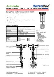
Principle of Measurement<br />
The principle of measurement is based on the incorporation of an orifice into the flow inside<br />
a pipe. Incorporating the orifice results in a difference between the static pressure of<br />
inlet and outlet of the throttle’s opening. The flow capacity can be determined by the<br />
measured effective pressure, the fluid’s properties, and by the operating conditions. (Picture<br />
1).<br />
The principle of measurement is so popular because related terms, definitions and specifications<br />
for equipment have been laid down in form of standards already at a very early<br />
stage.<br />
page 4<br />
BBM_man_e.doc
Manual<br />
BBM <strong>Blowby</strong>-<strong>Meter</strong><br />
pic 1<br />
Basis for Calculation<br />
Basis for Calculation is laid down in ISO 5167, VDI/VDE 2040 and VDI/VDE 2041.<br />
For estimates the following equations may be used:<br />
Liquid media:<br />
Gaseous media:<br />
Vaporous media:<br />
qm (kg/h) = 0,025 * d^2 * (pressure difference * density)^0,5<br />
qm (kg/h) = 0,025 * d^2 * Epsilon * (pressure difference * density)^0,5<br />
qm (kg/h) = 0,025 * d^2 * (pressure difference/density)^0,5<br />
qv<br />
= qm / density<br />
qn<br />
= qm / density (in relation to nominal conditions)<br />
qm<br />
= mass flow kg/h<br />
qv<br />
= volume flow rate m³/h<br />
d<br />
= diameter (of measuring hole) mm<br />
pressure difference = over the measuring orifice in mbar<br />
density<br />
= operating density kg/m³<br />
Epsilon<br />
= expansion constant (if pressure difference and<br />
pressure values differ very much, otherwise<br />
practice caution!))<br />
Factor<br />
= 0,025 (comprehends dimension states see<br />
VDI/VDE2040 and an assumed flow coefficient)<br />
BBM_man_e.doc page 5
Manual<br />
BBM <strong>Blowby</strong>-<strong>Meter</strong><br />
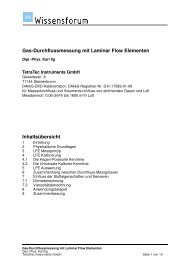
Modular Design of the Integrated Orifice<br />
The Integrated Orifice as produced and delivered by the manufacturer complies with all<br />
rules and regulations presently in force.<br />
The Integrated Orifice has both ATEX and FM certification.<br />
The Integrated Orifice complies with the guideline for pressure devices.<br />
In case of repair and maintenance works or any changes correct function may only<br />
be guaranteed by <strong>TetraTec</strong> <strong>Instruments</strong> <strong>GmbH</strong> if original parts are used and<br />
operating and assembly instructions are adhered to.<br />
1 Orifice device DPO10E<br />
2 Valve Manifold VB<br />
3 Differential Pressure Transmitter MU<br />
4 Circular Gasket<br />
5 Flat Gasket<br />
6 Screws<br />
Table 1<br />
page 6<br />
BBM_man_e.doc
Manual<br />
BBM <strong>Blowby</strong>-<strong>Meter</strong><br />
Applications Pre-Calculations and Calibration<br />
The compact orifice devices may be used for flow-rate measurement of gases,<br />
liquids and vapors.<br />
The orifice devices may be pre-calculated and manufactured according to norm<br />
(ISO5167), (VDI/VDE 2040/2041) and corresponding to customer needs.<br />
Calibration is always recommended for small nominal widths < 50 and for measuring bores<br />
< 12,5 mm or ß < 0,2 or. ß > 0,8.<br />
Specifications for Operations<br />
Nominal width: 6 to 15<br />
Nominal pressure:<br />
0,1 to 11 bar abs (option 41 bar abs)<br />
Temperature:<br />
-10 to +60°C<br />
Types of gaskets:<br />
B, C, D, E, F, L<br />
Redundant measurement: 2 of 3 e. g.<br />
Output signals:<br />
differential pressure, pressure, temperature, local<br />
display and flow-rate qm, qv, qn<br />
CENELEC-Approvals (e. g. Rosemount 3051C)<br />
Safety<br />
Pressure-proof housing<br />
Non incendive<br />
BAS97ATEX1089X<br />
II 1G EEx ia IIC T5 (To= -60 to +40°C)<br />
II 1G EEx ia IIC T4 (To= -60 to +70°C)<br />
U in max = 30 Vdc<br />
I in max = 200 mA<br />
P in max = 0,9 W<br />
Ceq = 0,012 µ F<br />
KEMA00ATEX2013X<br />
II 1/2 GD EEx d IIC T5 (To= -50 to +80°C)<br />
II 1/2 GD EEx d IIC T6 (To= -50 to +65°C)<br />
Dust rating T90°C IP66<br />
BAS00ATEX3105X<br />
II 3 GD EEx nL IIC T6 (To= -40 to 0°C)<br />
U in max = 55 Vdc<br />
Dust rating T80°C (To= -20 to 40°C) IP66<br />
BBM_man_e.doc page 7
Manual<br />
BBM <strong>Blowby</strong>-<strong>Meter</strong><br />
Dimensions and Weight<br />
Dimensions<br />
Mounting length and width:<br />
Length for sandwich construction 320 mm ,<br />
Width for sandwich construction min. 250 mm<br />
,<br />
Line connection<br />
G ¾” i<br />
(other mounting lengths upon request)<br />
Mounting height<br />
Differential PressureTransmitter<br />
MU (3051 CD)<br />
220 mm<br />
Valve Manifold VB +82 mm<br />
Integral orifice device see table (all figures are mm)<br />
DN 6 10 15<br />
PN 10 / 40 90,5 107,5 152<br />
Table 2 Mounting height integral orifice device DPO10E<br />
(other dimensions upon request)<br />
Weight<br />
Integral orifice device DPO10E<br />
DN PN kg<br />
6 - 15 40 1,8<br />
Table 3 (other dimensions upon request)<br />
Valve manifold VB<br />
Differential Pressure Transmitter MU (e. g. Rosemount 3051CD)<br />
2,1 kg<br />
2,3 kg<br />
page 8<br />
BBM_man_e.doc
Manual<br />
BBM <strong>Blowby</strong>-<strong>Meter</strong><br />
Mounting and Fitting into Pipe<br />
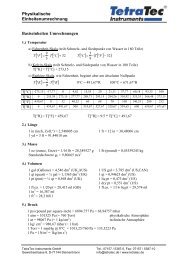
Orientation of the Pressure Taps<br />
Measuring Liquid Media<br />
pic 1<br />
Measuring Gaseous Media<br />
pic 2<br />
BBM_man_e.doc page 9
Manual<br />
BBM <strong>Blowby</strong>-<strong>Meter</strong><br />
Putting in Operation<br />
1. Fitting of the orifice device must be carried out according to rules and regulations<br />
regarding the installation of PLT-field devices presently in force. The orifice device<br />
must be fitted centrally when the in-line type (sandwich-installation) is installed.<br />
2. Electric connection must be performed according to the operating instructions of the<br />
MU’s manufacturer.<br />
3. When in operation, zero adjustment must be carried out immediately.<br />
4. The differential pressure output signal 4-20 mA is provided in linear mode (differential<br />
pressure mbar / current mA ).<br />
5. Data may be checked or new data may be entered with the HART-Communicator<br />
(250 Ohms resistance).<br />
6. The multi variable MU 3095 MA transmits a flow rate signal.<br />
7. Warning<br />
Before putting the orifice device in operation the specifications and certifications must be observed.<br />
Do not tighten or loosen any connecting bolts. The orifice device has undergone a pressure<br />
test before delivery.<br />
When using the valve manifold option be sure to proceed according to table 3 and<br />
choose the appropriate setting. Venting screws are designed to serve as pressure<br />
compensation in the pressure transmitter or to blow out the short differential pressure<br />
ducts. No hot water vapors must be blown out.<br />
page 10<br />
BBM_man_e.doc
Manual<br />
BBM <strong>Blowby</strong>-<strong>Meter</strong><br />
Switch Positions Valve Manifold<br />
Function Valve 1 Valve 2 Valve 3 Pos. of svalves<br />
Measuring open closed open 1<br />
Zeroadjustment,<br />
closed open closed 2<br />
pressure<br />
compensation<br />
at sensor<br />
of pressure<br />
transmitter<br />
Pressure<br />
compensation<br />
closed open closed 3<br />
when<br />
dismantling<br />
the pressure<br />
transmitter<br />
Venting Blowing<br />
out<br />
open closed open 4<br />
Putting in<br />
Operation<br />
open open open 5<br />
Leak Test<br />
Table 4<br />
BBM_man_e.doc page 11
Manual<br />
BBM <strong>Blowby</strong>-<strong>Meter</strong><br />
Flow Devices (Excerpt)<br />
Modular Parts<br />
Name of Part<br />
Material<br />
DPO10E DN 6 –15<br />
1.4571<br />
G ¼“ to ¾“<br />
Orifice 1.4571<br />
VB Standard 1.4404<br />
WI Standard 1.4408<br />
Differential Pressure Transmitter – Diaphragm<br />
1.4404<br />
material<br />
Table 5<br />
Connecting Bolts<br />
Name of Part<br />
Hexagon Head Bolt Inch<br />
7/16” UNF x 26<br />
Hexagon Head Bolt Inch<br />
7/16‘‘ UNF x 32<br />
Hexagon Head Bolt Inch<br />
7/16‘‘ UNF x 37<br />
Hexagon Head Bolt Inch<br />
7/16‘‘ UNF x 46<br />
Hexagon Socket<br />
M6 x 20<br />
Table 6<br />
Material<br />
A2-70<br />
A2-80<br />
A2-80<br />
A2-80<br />
A2-70<br />
page 12<br />
BBM_man_e.doc
Manual<br />
BBM <strong>Blowby</strong>-<strong>Meter</strong><br />
Gaskets<br />
Flat Gaskets<br />
Name of Part<br />
Flat Gasket Rosemount<br />
MU 30 x 26 x 2<br />
Table 7<br />
Material<br />
PTFE filled with glas<br />
Circular Gasket<br />
Name of Part<br />
Circular Gasket (Elastomere)<br />
25,07 x 2.62 Standard<br />
Circular Gasket (Elastomere)<br />
20 x 2.65 DIN<br />
Circular Gasket (Elastomere)<br />
10 x 2 DIN<br />
Table 8<br />
Material<br />
FFKM (Simriz)<br />
Kalrez 6375<br />
FFKM (Simriz)<br />
Kalrez 6375<br />
FFKM (Simriz)<br />
Kalrez 6375<br />
Assembly and Checks of the Integrated Orifice<br />
Application and Visual Check<br />
Assembly<br />
Only parts listed in tables 1 to 8 may be used to install the compact orifice<br />
device.<br />
All parts of the custom-made orifice device must undergo a visual check for<br />
damage or any instructions marked on the device.<br />
P1. Mount differential pressure transmitter (standard connection MU<br />
Rosemount 3051CD without coplanar flange) onto modular parts such as<br />
DPO10E with measuring orifice, VB or WI (at an angle of 90° for vaporous<br />
media).<br />
P2. Insert original gasket (Rosemount Typ 3051) into part at MU-side and<br />
connect modular part with bolts (table 6) according to the following<br />
procedure (previously fitted gasket still inside the MU may be used if<br />
undamaged).<br />
BBM_man_e.doc page 13
Manual<br />
BBM <strong>Blowby</strong>-<strong>Meter</strong><br />
P3. Apply fitting paste (manufactured by OPTIMOL Ölwerke <strong>GmbH</strong>, Munich,<br />
Product-No. 08464-215) to top of all five threads as well as at the<br />
transition of shaft and head.<br />
P4. Screw bolts crosswise into the part with the threads using a torque meter,<br />
tightening them – one by one and in several goes – to the same torque<br />
level (torque 40 Nm).<br />
P5. Tighten bolts crosswise – one by one and in several goes – to the<br />
maximum torque level (torque 50 Nm).<br />
P6. Check clearance of fastened parts using a feeler gauge; clearance<br />
between fastened parts must be evenly ≤ 0,1 mm.<br />
P7. Wait 60 min ( see P5. ).<br />
P8. Check – one bolt after the other – in crosswise direction if bolts are still<br />
tightened at maximum torque (50 Nm ).<br />
P9. Fit MU (DIN 19213 – Pressure Transmitter Connection) onto<br />
integral orifice device DPO10E.<br />
P10. Fit universal gasket (table 8) (Elastomere) circular gaskets on the module<br />
side and connect MU with bolts (table 6) according to the following<br />
procedure:<br />
P11. Prepare bolts as in P3.<br />
P12. Screw bolts crosswise into the part with the threads using a torque meter,<br />
tightening them – one by one and in several goes – to the same torque<br />
level (torque 50 Nm).<br />
P13. Check clearance of fastened parts using a feeler gauge; clearance<br />
between fastened parts must be evenly ≤ 0,1 mm.<br />
P14. Fitting of integral orifice device DPO10E (standard connection) onto<br />
modular parts VB or WI (at an angle of 90° when used for vapors).<br />
P15. Put VB (table 4) into switch position 5 when fitting it.<br />
P16. Insert circular gaskets (table 8) (Elastomere) in modular part VB and<br />
connect parts with bolts (table 6) as in P3. and P4. (50 Nm).<br />
P17. Check clearance of fastened parts as in P13.<br />
P18. Fitting of integral orifice device DPO10E (DIN pressure transmitter<br />
connection) onto modular parts VB or WI (at an angle of 90° when used<br />
for vapors).<br />
P19. Put VB (table 4) into switch position 5 when fitting it.<br />
P20. Insert circular gaskets (table 8) (Elastomere) into modular part DPO10E and<br />
connect parts with bolts (table 6) as in P3. und P12. at a torque of 50 Nm.<br />
P21. Check clearance of fastened parts as in P13.<br />
page 14<br />
BBM_man_e.doc
Manual<br />
BBM <strong>Blowby</strong>-<strong>Meter</strong><br />
Pressure Check<br />
Procedure<br />
Seal DPO10E with a blind flange as well as connecting flange for pressure admission.<br />
When checking with gaseous media at high nominal pressures be sure to reduce volume<br />
as much as possible for safety reasons.<br />
After the measuring device has been sealed with flanges and the valves 1,2,3 have been<br />
opened on the VB (switch position 5 [see 3.3 page 10]), it is lowered into a water bath as far<br />
as over the connection to the MU.<br />
Admit pressure evenly, not abruptly up to the test pressure level.<br />
The measuring device is kept at the test pressure level for five minutes; check for any rising<br />
water bubbles; if there are no bubbles the pressure check has been completed.<br />
Use water or nitrogen as test medium.<br />
Pressure check is performed at a test pressure of 130 % of nominal pressure for liquids or<br />
110 % of nominal pressure for gaseous media.<br />
Abbreviations<br />
DPO10E = Integral orifice device built into pipe<br />
MU = Differential pressure transmitter<br />
VB = Valve manifold for testing and shutting off<br />
DIN = Pressure transmitter connection in compliance with DIN 19213<br />
Standard = Pressure transmitter connection for Rosemount MU 3051CD and 3095 MA without<br />
coplanar flange<br />
WI = Angle for measurement of vaporous media (formation of condensate)<br />
GDB = Device data sheet for the flow measuring device (Integrated Orifice)<br />
8. Richtlinie 97/23/EG (Druckgeräterichtlinie)<br />
Contact<br />
Gewerbestr. 8<br />
71144 Steinenbronn<br />
Tel. +49-(0)7157/53 87-0<br />
Fax +49-(0)7157/53 87-10<br />
Email: info@tetratec.de<br />
Internet: www.tetratec.de<br />
BBM_man_e.doc page 15