LMF-V5 Manual - TetraTec Instruments GmbH
LMF-V5 Manual - TetraTec Instruments GmbH
LMF-V5 Manual - TetraTec Instruments GmbH
- No tags were found...

You also want an ePaper? Increase the reach of your titles
YUMPU automatically turns print PDFs into web optimized ePapers that Google loves.
Operating Instructions andReference <strong>Manual</strong><strong>LMF</strong>Table of Contents1 INTRODUCTION ............................................................................................................................ 11.1 Product description...................................................................................................................11.1.1 Hardware.................................................................................................................................11.1.2 Software ..................................................................................................................................11.2 Proper use..................................................................................................................................21.3 Warranty and Liability...............................................................................................................32 SAFETY.......................................................................................................................................... 42.1 Basic Safety Instructions .........................................................................................................42.1.1 Responsibility of the Operator.................................................................................................42.1.2 Responsibility of the Staff........................................................................................................42.1.3 Inevitable remaining dangers by the equipment .....................................................................42.2 Safety notes for the operation of the device ..........................................................................62.2.1 Set-up, installation...................................................................................................................62.2.2 Operating conditions, ambient conditions ...............................................................................62.2.3 Power supply, electric connection of devices with mains connection.....................................62.2.4 Power supply of OEM devices ................................................................................................62.2.5 Cleaning of the device.............................................................................................................62.2.6 Behaviour after turn-on of type PLC .......................................................................................62.2.7 Calibration, measuring accuracy.............................................................................................72.2.8 Structural changes on devices and measuring sections.........................................................72.3 Limit parameter access ............................................................................................................82.3.1 Level allocation of the parameters ..........................................................................................82.3.2 Definition of users and their right of access............................................................................83 COMPONENTS OF A <strong>LMF</strong> SYSTEM .......................................................................................... 103.1 Overview...................................................................................................................................103.2 Primary elements.....................................................................................................................113.2.1 Active pressure transmitter ...................................................................................................113.2.2 Counter..................................................................................................................................123.2.3 Miscellaneous .......................................................................................................................124 OPERATIONAL CONTROLS ...................................................................................................... 134.1 Front panel operational controls of Controller S320 ...........................................................134.2 Interfaces of Controller S320 .................................................................................................154.3 Additional front panel operational controls with installation in a recumbent 19“ cabinet164.4 Back side interfaces with installation in a recumbent 19“ cabinet ....................................175 INTERFACES FOR REMOTE CONTROL................................................................................... 185.1 Set up RS232 interface............................................................................................................185.1.1 Default settings in the configuration file: ...............................................................................185.1.2 Interface settings in the terminal program.............................................................................195.1.3 Test function of the serial interface .......................................................................................195.1.4 Test function of the link interface ..........................................................................................195.2 Set up network interface.........................................................................................................195.2.1 Enter IP address ...................................................................................................................195.2.2 Adjust port number................................................................................................................195.2.3 Set IP address and port number in the terminal program.....................................................205.2.4 Test connection.....................................................................................................................205.2.5 Restrictions of access ...........................................................................................................20<strong>LMF</strong> <strong>V5</strong>.8Page iii
Operating Instructions andReference <strong>Manual</strong><strong>LMF</strong>5.3 Query and change of parameters ..........................................................................................225.3.1 Physical units ........................................................................................................................225.3.2 Query parameters .................................................................................................................225.3.3 Change parameters ..............................................................................................................225.4 Virtual inputs and outputs......................................................................................................245.4.1 Communication .....................................................................................................................245.4.2 Timeouts................................................................................................................................245.4.3 Access control.......................................................................................................................255.5 List of the remote control commands of the COMM interface............................................265.5.1 CONTROL.............................................................................................................................265.5.2 CTD.......................................................................................................................................265.5.3 CTI.........................................................................................................................................265.5.4 CVP .......................................................................................................................................265.5.5 DATE.....................................................................................................................................275.5.6 DEFAULTS............................................................................................................................275.5.7 DISCARD ..............................................................................................................................275.5.8 DLIST ....................................................................................................................................275.5.9 DMODE .................................................................................................................................285.5.10 DPAGE .............................................................................................................................285.5.11 EDITMENU .......................................................................................................................285.5.12 EVAL.................................................................................................................................285.5.13 FACDBG ...........................................................................................................................285.5.14 GASMIX ............................................................................................................................295.5.15 HELP.................................................................................................................................295.5.16 INPUT ...............................................................................................................................305.5.17 IVALVE .............................................................................................................................305.5.18 IZERO ...............................................................................................................................305.5.19 LASTSTATES...................................................................................................................315.5.20 LEAK.................................................................................................................................315.5.21 LOGLEVEL .......................................................................................................................315.5.22 MEAS................................................................................................................................315.5.23 OUTPUT ...........................................................................................................................315.5.24 PORTMAP ........................................................................................................................315.5.25 PRIMARY..........................................................................................................................325.5.26 PROG ...............................................................................................................................325.5.27 PROGMENU.....................................................................................................................325.5.28 QUIT .................................................................................................................................325.5.29 RPAR ................................................................................................................................325.5.30 SAVE ................................................................................................................................335.5.31 SCRIPTINFO ....................................................................................................................335.5.32 SISEND.............................................................................................................................335.5.33 STOP ................................................................................................................................335.5.34 TEMP ................................................................................................................................345.5.35 TESTMENU ......................................................................................................................345.5.36 TIMESTAT ........................................................................................................................345.5.37 VERS ................................................................................................................................345.5.38 ZERO ................................................................................................................................346 SYNTAX ....................................................................................................................................... 356.1 Figure formats for the input of numerical parameter values..............................................356.2 Format strings for protocol printout functions ....................................................................356.3 Control expressions................................................................................................................366.3.1 Operators and their priorities.................................................................................................366.3.2 Variables ...............................................................................................................................376.3.3 Functions...............................................................................................................................387 OPERATION MODES .................................................................................................................. 407.1 STANDARD MODE...................................................................................................................40Page iv <strong>LMF</strong> <strong>V5</strong>.8
Operating Instructions andReference <strong>Manual</strong><strong>LMF</strong>7.1.1 Program selection .................................................................................................................407.2 LEAK TESTING ........................................................................................................................407.3 MEASUREMENT by taking the mean.....................................................................................417.4 Special modes for the experienced user ..............................................................................417.4.1 Test mode .............................................................................................................................417.4.2 Controller mode.....................................................................................................................427.4.3 Nullification............................................................................................................................447.4.4 Editing mode .........................................................................................................................458 PARAMETER STRUCTURE........................................................................................................ 478.1 Parameter structure and overview ........................................................................................478.1.1 C parameter nozzle combinations ........................................................................................478.1.2 D Parameter display configurations ......................................................................................478.1.3 E parameter extension flow elements...................................................................................478.1.4 F parameter switch over vectors...........................................................................................478.1.5 I parameter initialization analog outputs ...............................................................................478.1.6 M-Parameter – gas mixtures.................................................................................................478.1.7 P-Parameter – measuring programs.....................................................................................488.1.8 R parameter - read parameter, measurement results of the measuring programs ..............498.1.9 S-parameter - system parameter ..........................................................................................508.1.10 U parameter - sub programs.............................................................................................509 LIST OF PARAMETERS.............................................................................................................. 519.1 C parameter: nozzle combinations........................................................................................519.2 D parameter: display lists.......................................................................................................519.2.1 D0000-D0049 block: linkage program mode with display list ...............................................519.2.2 D0100-D0499 block: linkage of display pages to a display list.............................................529.2.3 D1000-D1999 block: definitions of the display pages...........................................................539.3 E parameter: extension primary elements............................................................................549.4 F parameters: switch over vectors ........................................................................................549.5 I parameter: initial values of outputs.....................................................................................559.5.1 I0200 block: initial values of impulse valves .........................................................................559.6 M parameter: gas mixtures.....................................................................................................569.6.1 M0xxx block: definition of gas mixtures ................................................................................569.7 S parameter: system parameter.............................................................................................579.7.1 S0000 block: general parameters .........................................................................................579.7.2 S0350 block: error conditions of inputs and outputs.............................................................599.7.3 S0500 block: user administration..........................................................................................609.7.4 S1000 block: preselection of program ..................................................................................609.7.5 S1100 block: stabilization period nullification........................................................................619.7.6 S1200 block: flip-flops (flags)................................................................................................619.7.7 S1300 block: virtual outputs..................................................................................................629.7.8 S1400 block: SPS control inputs...........................................................................................629.7.9 S1500 block: input/output allocations ...................................................................................649.7.10 S1600 block: impulse valves ............................................................................................659.7.11 S1800 block: digital outputs..............................................................................................679.7.12 S2000/S3000 block: analog input channels .....................................................................679.7.13 Extended parameter set for integrated analog inputs ......................................................699.7.14 Extended parameter set for serial analogs inputs ............................................................699.7.15 Extended parameters set for R parameter as inputs........................................................699.7.16 Extended parameter set for integrated counter inputs .....................................................709.7.17 S4000-S7000 block: Linearization and type of primary elements ....................................719.7.18 Extended parameter set for leakage measuring (LMS)....................................................729.7.19 Extended parameter set for critical nozzles......................................................................729.7.20 Extended parameter set for orifices..................................................................................729.7.21 Extended parameter set for gas meters ...........................................................................73<strong>LMF</strong> <strong>V5</strong>.8Page v
Operating Instructions andReference <strong>Manual</strong><strong>LMF</strong>9.7.22 Extended parameter set for accutubes.............................................................................739.7.23 Extended parameter set for betaflow................................................................................739.7.24 S8000 block: linearization outputs ....................................................................................749.7.25 Extended parameter set for integrated analog outputs ....................................................749.7.26 S9000 block: special functions .........................................................................................759.7.27 S9300 block: protocol printout ..........................................................................................769.7.28 S9500 block: definition of connection for virtual inputs and outputs.................................789.8 P parameter: measuring program definitions ......................................................................799.8.1 Px000 block: primary element, basic description..................................................................799.8.2 Px010 block: primary measured variable..............................................................................799.8.3 Px020 block: test pressure absolute (Pabs) .........................................................................809.8.4 Px030 block: measuring temperature (Tem).........................................................................819.8.5 Px040 block: measuring humidity (Hum) ..............................................................................819.8.6 Px050 block: reference pressure absolute (PabsB) .............................................................819.8.7 Px060 block: reference temperature (TemB)........................................................................839.8.8 Px070 block: reference humidity (HumB) .............................................................................839.8.9 Px075 block: auxiliary input 0 (Aux0)....................................................................................849.8.10 Px080 block: auxiliary input 1 (Aux1) ...............................................................................859.8.11 Px085 block: auxiliary input 2 (Aux2) ...............................................................................869.8.12 Px090 block: auxiliary input 3 (Aux3) ...............................................................................879.8.13 Px095 block: auxiliary input 4 (Aux4) ...............................................................................889.8.14 Px100 block: volume flows/ frequencies...........................................................................889.8.15 Px120 block: mass flow ....................................................................................................899.8.16 Px130 block: heating capacity ..........................................................................................909.8.17 Px140 block: density.........................................................................................................909.8.18 Px160 block: viscosity.......................................................................................................919.8.19 Px180 block: speed ..........................................................................................................919.8.20 Px190 block: pressure drop ..............................................................................................919.8.21 Px300 block: ratio formation .............................................................................................939.8.22 Px310 block: functions......................................................................................................949.8.23 Px350 block: calculated R parameters .............................................................................969.8.24 Px400 and Px450 blocks: control .....................................................................................989.8.25 Px500 block: limit values ................................................................................................1009.8.26 Px550 block: automatic program toggle .........................................................................1019.8.27 Px700 block: process times ............................................................................................1019.8.28 Px800 block: display parameters depending on the program ........................................1029.8.29 Px900 block: analog outputs...........................................................................................1039.9 U parameter: sub programs .................................................................................................1039.10 Ryxxx block: readparameter, measurement results..........................................................10610 BASIC UNITS – CONVERSION (X AND Y FACTORS)............................................................ 11411 INDICATIONS TO THE METHODS OF CALCULATION.......................................................... 11811.1 Ideal gas law ..........................................................................................................................11811.2 Correlation between the flow measured variables ............................................................11811.3 Adjustable kinds of gas ........................................................................................................11911.4 Density calculation................................................................................................................12011.5 Viscosity calculation.............................................................................................................12111.6 Measuring sensors and reference sensors ........................................................................12111.6.1 Measuring sensors .........................................................................................................12211.6.2 Reference sensors..........................................................................................................12311.6.3 Auxiliary ..........................................................................................................................12411.7 Correction calculations.........................................................................................................12511.7.1 Correction calculations of the <strong>LMF</strong> (S9200) ...................................................................12511.7.2 Example: corrected mass flow........................................................................................12711.7.3 Calibration of the <strong>LMF</strong> by using calibration leaks...........................................................128Page vi <strong>LMF</strong> <strong>V5</strong>.8
Operating Instructions andReference <strong>Manual</strong><strong>LMF</strong>12 LINEARIZATION OF SENSORS AND PRIMARY ELEMENTS ................................................ 12912.1 Linearization of the analogous value sensors with analogous or serial output ............12912.2 Linearization of primary elements .......................................................................................13012.2.1 LFE according to Hagen-Poiseuille ................................................................................13012.2.2 LFE according to Universal Flow....................................................................................13112.2.3 Overcritical nozzles according to DIN EN ISO 9300 ......................................................13112.2.4 Gas meter .......................................................................................................................13112.2.5 Orifices, Venturi tubes, Pitot tubes / Accutubes... ..........................................................13113 ALLOCATION OF THE SENSORS AND PRIMARY ELEMENTS ............................................ 13214 MEASURING AND CORRECTION PROCESSES .................................................................... 13415 UNCERTAINTY OF MEASUREMENT BUDGET ...................................................................... 13615.1 Basic considerations Qv , Qm , ρ(p , T, xv) .........................................................................13615.2 Percentage of uncertainty of measurement caused by leakage in the test section design13615.3 Uncertainties of measurement on comparative measurements with Laminar FlowElements:.............................................................................................................................................13715.4 Uncertainties of measurement with comparative measurements with orifices: ............13815.5 Uncertainties of measurement with comparative measurements with critical nozzles:13916 PLC INTERFACE ....................................................................................................................... 14016.1 PLC modes of operation.......................................................................................................14016.2 Overview of test steps and functions..................................................................................14016.3 Detailed information for the particular test steps ..............................................................14216.3.1 Wait for PLC start ...........................................................................................................14216.3.2 Program selection...........................................................................................................14216.3.3 Pre-fill..............................................................................................................................14316.3.4 Fill ...................................................................................................................................14316.3.5 Calm................................................................................................................................14316.3.6 Measuring .......................................................................................................................14316.3.7 Evaluate result ................................................................................................................14416.3.8 Display results.................................................................................................................14416.3.9 Ventilation .......................................................................................................................14416.3.10 Display result digitally .....................................................................................................14416.3.11 Wait for PLC stop............................................................................................................14516.4 Overview of the signals ........................................................................................................14516.4.1 Control inputs..................................................................................................................14516.4.2 Control outputs................................................................................................................14516.4.3 Status outputs .................................................................................................................14516.4.4 Result outputs .................................................................................................................14516.5 Standard configuration of the PLC digital interface ..........................................................14616.6 Schematic signal functions..................................................................................................14816.6.1 Regular testing schedule ................................................................................................14816.6.2 Testing schedules with malfunction................................................................................149<strong>LMF</strong> <strong>V5</strong>.8Page vii
Operating Instructions andReference <strong>Manual</strong><strong>LMF</strong>1 Introduction1.1 Product descriptionThe <strong>LMF</strong> system consists of hardware and software.1.1.1 HardwareController S320 and one or several measuring sections are vital components of the hardware.The controller in its core consists of a very accurate floating point calculator in a standard switchboardinstallation rack. A very high flexibility is given by the modularity of the hardware and software.The controller can be inserted in cases specific for application. To make easier the specific operationof the application, these cases can be equipped with additional buttons, displays or a PLC interface.The measuring sections can also be inserted in the case according to size and number, be mountedon a mounting plate or be supplied loosely. Measuring sections typically consist of an arrangement ofvolumes or flow elements and connected sensors and/or correcting elements.For being able to communicate with the analog or digital sensors, final control elements or a PLC, thecontroller is equipped with plug-in cards according to the application. In addition to various plug-incards for special jobs the following plug-in cards are used frequently:Typ100-KartenTyp200-KartenTyp310-KarteTyp400-KarteTyp500-KarteTyp510-KarteTyp520-KarteTwo analog-digital convertersTwo digital-analog convertersAn analog-digital converter and a digital-analog converter each, 14 bit each, cycletime only 10 ms, conversion time 3ms. Hence, particularly suitable for fast control.Bus module for digital extension modules, e.g., for PLC interfaceTwo inputs for pulse transmittersTwo frequency countersTwo frequency generators with adjustable pulse-width modulationFor detailed information and other cards please see our homepage.1.1.2 SoftwareThe software is arranged hierarchically:• Operating system• Config (registration and linearization of the plug-in cards, if necessary, and configuration of theserial interfaces)• <strong>LMF</strong> software, initialized specifically for application• Switchable parameter sets for different measuring tasks (program 0 to 9)Originally there has been different software for different types of application. But over and over againthere have been requests for measuring systems exceeding the limitations between the softwarepackages. Thus these different software packages have been integrated in the <strong>LMF</strong> software versionby version. The applications now result from the specific configuration of the software. The <strong>LMF</strong>software therefore includes the following applications:<strong>LMF</strong> LaminarMasterFlow Originally for the evaluation of Laminar Flow Elements(LFE), in the meantime generally for the evaluation ofprimary elements for flow measurements, i.e., in additionto LFEs also orifices, nozzles, Pitot tubes, gas meters etc.Combined with actuators also for the regulation ofpressure and flow.PCS PressureControlSystem For pressure controlLFC LaminarFlowControl Flow meterLMS LeakageMeasuringSystem Leakage measuring in closed volumesCVS-CAL Constant Volume SamplingCalibrationCalibration equipment for CVS devices<strong>LMF</strong> <strong>V5</strong>.8 Page 1
Operating Instructions andReference <strong>Manual</strong><strong>LMF</strong>1.2 Proper useThe devices of the series <strong>LMF</strong> are exclusively determined according to the sales confirmation• for measuring and controlling of- volume flow- mass flow- pressure• For the calibration of other devices measuring and controlling such parameters• For metering of gaseous media• For leak testingApproved as a medium are (according to the sales confirmation)• air• gases- argon- carbon dioxide- carbon monoxide- helium- hydrogen- nitrogen- oxygen- methane- propane- n-butane- natural gas- laughing gasNote:The proper use is exclusively restricted to the application and the media specified in the salesconfirmation. I.e., even the use for one of the purposes mentioned above and the operation with amedium mentioned above will be recognized as improper use, provided that the device has not beenspecified for that purpose!Tests and an approval in written form will be required with changes by <strong>TetraTec</strong> <strong>Instruments</strong> <strong>GmbH</strong>.When being used as a measuring unit in complex machines, a combination of machines, an assemblyline or system, the signal outputs must exclusively be used for the information of a superior control(e.g. PLC).When being used as an independent laboratory measuring instrument with control function theregulations and indications for emergency stop functions and for the recovery of voltage after powerfailure must be observed.Proper use is also including• observing of all notes of the operating instructions• observance of the inspection and maintenance work.Other or expanded uses will be regarded as improper use. <strong>TetraTec</strong> <strong>Instruments</strong> will not be liable forany damages arising from that.Page 2 <strong>LMF</strong> <strong>V5</strong>.8
1.3 Warranty and LiabilityOperating Instructions andReference <strong>Manual</strong><strong>LMF</strong>Our „General Sales and Delivery Specifications“ are valid in principle. They will be available for theoperator by the conclusion of a contract at the latest. Warranty and liability claims in the case ofdamages to persons and property will be excluded, if they are caused by one or more of the followingreasons:• Improper use of the device.• Faulty installing, taking into operation, operating and maintaining of the device and of theaccessories (sensors, LFE).• Operating of the device with defect safety equipment or safety and protection devices beinginstalled improperly or not operatively.• Ignoring of the instructions of the operating instructions in regard of transport, storage, installation,taking into operation, operation, maintenance and setting of the device.• Arbitrary structural changes of the device, arbitrary changing of the measuring section and of themeasurement set-up.• Inadequate monitoring of accessory parts being subject to wear.• Repairs performed faulty.• Disasters resulting from circumstances caused by a third party or force majeure.<strong>LMF</strong> <strong>V5</strong>.8 Page 3
Operating Instructions andReference <strong>Manual</strong><strong>LMF</strong>2 SafetyPlease get used to the safety instructions absolutely before the installation is started!2.1 Basic Safety InstructionsA basic requirement for a save handling and a trouble-free operation of this equipment is theknowledge of the basic safety instructions and of the safety regulations.This operating instructions, particularly the safety instructions, must be observed by all personsworking with the equipment.Furthermore the rules and regulations for the prevention of accidents valid for the site must beobserved.2.1.1 Responsibility of the Operator• The operator is responsible that only persons will be working with the equipment who have beenget used to the basic regulations of safety of work and prevention of accidents and who have beeninstructed in the handling of the equipment.• The responsibility of the staff must be clearly determined for the mounting, taking into operation,operating, setting and servicing.• The safety-conscious working of the staff will be inspected regularly.2.1.1.1 Training of the Staff• Only trained and introduced staff must work with the equipment.• The staff must have read, understood and confirmed by signature the safety chapter and thewarning notes included in this operating instructions.• Staff to be trained must only work with the equipment being supervised by an experienced person.2.1.1.2 Informal Safety Measures• The operating instructions have to be kept at the location of the equipment all the time.• Complementary to the operating instructions the generally accepted and local regulations for theprevention of accidents and for environmental protection must be provided and be observed.• All instructions for safety and danger of the equipment and of the measuring section have to bekept legibly.2.1.2 Responsibility of the StaffAll persons having been ordered to work on the equipment will be responsible before starting work• to observe the basic regulations of the safety of work and the prevention of accidents.• to read the safety chapter and the warning notes of this operating instructions and to confirmhaving read and understood them with their signature.2.1.3 Inevitable remaining dangers by the equipmentThe devices of the series <strong>LMF</strong> have been constructed according to the state of the art and therecognized safety regulations. However, it is possible that by their use danger for life and physicalcondition of the operator or a third person or damage of the equipment or other real values may occur.The devices must only be used• for proper use• and in a correct safety condition.Malfunctions which may have impact on the safety must immediately be corrected.Page 4 <strong>LMF</strong> <strong>V5</strong>.8
2.1.3.1 Dangers by Electric EnergyOperating Instructions andReference <strong>Manual</strong><strong>LMF</strong>Only an electric specialist must be allowed to work on the power supply.Check the electrical equipment of the machine regularly. Immediately remove loose connectionsand broken cables and replace them by new cables.All necessary repairs must be performed by a certified service engineer of <strong>TetraTec</strong> <strong>Instruments</strong>.If work is indispensable on voltage-carrying components, a second person should be consulted toswitch off the main switch, if necessary.CAUTION: TO EXCLUDE FIRE RISK OR DANGER OF AN ELECTRIC IMPACT, PROTECT THEDEVICE FROM RAIN, MOISTURE AND EXCESSIVE HUMIDITY.2.1.3.2 Dangers by extrinsic gases(applies only if gaseous media other than air are used)Gases have the following dangerous properties depending on the type of gas:• Oxygen and laughing gas have a fire-supporting impact• Laughing gas and xenon have a hallucinogenic or anesthetic to toxic impact according to theirconcentration• Carbon monoxide is toxic• Hydrogen, carbon monoxide and the hydrocarbons as for example propane are ignitable and mayform explosive mixtures when being mixed with air• By admixing gases (except oxygen) to the breath air its concentration of oxygen will decline, sothat a suffocating effect with high concentrations will be initialized.Therefore: Avoid emission of extrinsic gases. Discharge dispersing extrinsic gases to exhaust gas system. Possibly work in a well ventilated environment. Examine measuring setup regularly for leakage.2.1.3.3 Dangers by pressureInsufficiently fixed or aged flexible tubings, pipes etc. may become loosely or may burst. Possibleconsequences:• Parts may fly or whirl around and may cause damages or injuries.• Involuntary movements or distractions caused by frightening may cause damages to property,injuries etc.• Strong noise development, thus reduction of the response time and risk of hearing damages.<strong>LMF</strong> <strong>V5</strong>.8 Page 5
Operating Instructions andReference <strong>Manual</strong><strong>LMF</strong>2.2 Safety notes for the operation of the device2.2.1 Set-up, installationThe device must be set-up completely sealed at a dry place free of dust and free of vibration. Thecabinet must not be opened at all. There are no parts in it to be maintained by the user / customer.The opening and vent holes of the cabinet must not be covered. Sufficient aerial circulation has to beprovided. A clearance of at least 1 cm must be guaranteed on the bottom side of the device.With assembly in a switch cupboard / built-in cupboard the operating temperature limits must beobserved.With loosely delivered measurement value transducers and primary elements it must be observed thatthe installation is free of contamination and in correct positional arrangement on the measuring point.If necessary, sensitive readings recorders must be particularly protected against damage.The sensors and primary elements must not be exchanged or be allocated wrongly at all.The allocation to the suitable measuring channel as well as to the suitable device must be absolutelykept. If the assembly / connection is exchanged, the calibration of the devices will get lost.If sensors are integrated in the device it must be put up horizontally.2.2.2 Operating conditions, ambient conditionsOperating temperature: 5°C to 40°C.working pressure: atmospheric pressurerange of humidity: 0...90% of relative humidity, not condensing!Before the device is turned on it must be adapted to the room temperature, the device must not bewith dew at all.2.2.3 Power supply, electric connection of devices with mains connection110 - 230 VAC (50/60 hertz) for devices with mains connection:Only the provided power cords or power cords with equivalent test sign must be used. The quality ofthe power supply must be according to EN 60204.24 VDC for devices with control voltage supply:Caution: The connection of the cabinet (protective earth) must be carried out with themains connectors located in the back wall!2.2.4 Power supply of OEM devicesController S320 is supplied with 24 V.2.2.5 Cleaning of the deviceWipe with moist cloth2.2.6 Behaviour after turn-on of type PLCThe device can be configured in such a way that it will run in the automatic test cycle mode when it isturned on after a power supply failure and voltage has returned.In this mode some of the digital control outputs are active!The operator is responsible for the protection against a restart of the machines /assemblies controlled by the PLC, which may be immediately dangerous for personsand appliances!Page 6 <strong>LMF</strong> <strong>V5</strong>.8
2.2.7 Calibration, measuring accuracyOperating Instructions andReference <strong>Manual</strong><strong>LMF</strong>The devices are delivered by <strong>TetraTec</strong> <strong>Instruments</strong> being calibrated and readily configured. Anychange of the calibration coefficient or other scaling factors and constants used internally may makethe calibration invalid or reduce the measuring accuracy.2.2.8 Structural changes on devices and measuring sectionsAll measures of conversion require tests and written approval by <strong>TetraTec</strong> <strong>Instruments</strong>. No changes, attachments or conversions of the device or measuring section must be carried outwithout approval of the manufacturer. Only use original spare parts and wearing parts.Parts supplied by third companies will have no guarantee of being constructed and manufacturedappropriately in regard of stress and safety , or that they meet metrological requirements.• The exchange of sensors and laminar sections must be coordinated with <strong>TetraTec</strong> <strong>Instruments</strong>,since a new measurement may be necessary possibly.• Only sensors and laminar sections supplied and calibrated by <strong>TetraTec</strong> <strong>Instruments</strong> must be used.<strong>LMF</strong> <strong>V5</strong>.8 Page 7
Operating Instructions andReference <strong>Manual</strong><strong>LMF</strong>2.3 Limit parameter accessIt is possible to limit the parameter access in the editing mode.The first paragraph of this chapter explains, according to which scheme the parameters are allocatedto access levels defined by the factory. In the second paragraph there is information about thedefinition of own user groups and a documentation of the user groups preset by the factory and theirpasswords.Note:The operator or his system administrator is responsible for the changing of at least the passwords, todocument them and to keep this documentation at a save place.Further information• For the consequences of the restrictions of access in the editing mode see chapter 7.4.4.2• Access restriction for TCP connection see chapter 5.2.52.3.1 Level allocation of the parametersAn amount of levels is allocated to each single parameter by the factory. This is carried out by theattribute „level=n“. Here „n“ is a number the single bits of which encode the respective level.ExamplesTerm = ExplanationBinarylevel=1 0001 parameter is only accessible in level 0level=12 1100 parameter is accessible in levels 2 and 3level=9 1001 parameter is accessible in levels 0 and 32.3.2 Definition of users and their right of accessUp to 10 users can be defined in the block S05XX. Each user has a designation (e.g. „setter“), apassword, and an amount of levels which he is able to access. Just like the allocation of theparameters the allocation of users to levels is carried out by indicating a number, the particular bits ofwhich indicate whether the user has access to the parameters in this level or not.ExampleS0500="Egon"S0501=1S0502=1234S0500="Egon"S0501=7S0502=1234These parameters define a user with the name „Egon“ (this name has to be selectedwhen entering the editing mode). The user’s password is „1234“ and he has accessto all parameters which are visible in level 0 (since 1 = 0001 binary)As above, but the user „Egon“ has only access to parameters of the levels 0, 1 and 2(since 7 = 0111 binary).Further information• For block S05XX see chapter 9.7.3Page 8 <strong>LMF</strong> <strong>V5</strong>.8
Operating Instructions andReference <strong>Manual</strong><strong>LMF</strong>Default settingNormally four users are defined, to whom exactly one level is allocated each. The appropriate fourlevels are arranged hierarchically in ascending order (i.e., the superior levels include all parameters ofthe lower levels respectively) The password is the number of the level respectively:Name Password Access to parameters"Level 0" 0 Px500 to Px523"Level 1" 1 Px400 to Px499 andPx500 to Px523 andPx701 to Px722"Level 2" 2 M0000 to M0999 andPx000 to Px999 andS0000 to S0013 andS0100 to S0311"<strong>TetraTec</strong>" 3 C0000 to C0199 andD0000 to D1999 andE0000 to E9999 andI0200 to I0209 andM0000 to M0999 andPx000 to Px999 andS0000 to S9999NoteIt goes without saying that the level „<strong>TetraTec</strong>“ is only left for authorized staff (i.e., with the exceptionof changing passwords by the operator or his system administrator only employees of <strong>TetraTec</strong><strong>Instruments</strong> <strong>GmbH</strong>), since the changing of basic parameters may result in considerable negativeconsequences.<strong>LMF</strong> <strong>V5</strong>.8 Page 9
Operating Instructions andReference <strong>Manual</strong><strong>LMF</strong>3 Components of a <strong>LMF</strong> System3.1 OverviewAccording to the application different components are used, i.e., your system must not be equippednecessarily with all described components. The following table gives an overview of the componentsand their main operational areas.Evaluation electronic Heart of the evaluation electronic is controller S320 with various interfacecards. For a description see chapters 1.1.1 and 4.InterfacesThe evaluation electronic can display the computed values by digital andanalog interfaces. Analog outputs are also used fort he activation of actuators,e.g., of proportional valves.Protective cabinets Depending on the desired protective class different protective cabinets areavailable. Depending on the size of the measuring section the protectivecabinet can also accommodate sensors or even the complete measuringsection in addition to the evaluation electronic and the power pack.Primary elements Primary elements is the generic term for LFEs, orifices, Pitot tubes, etc., whichare used for flow measurement. Important sub-groups are:• Active pressure transmitter• Counter• Thermal mass flow meter sensorsThe most current primary elements are described in detail in the followingparagraph.Differential pressure Differential pressure sensors are used, for example, for the measurement ofsensorsthe active pressure of active pressure transmitters.Absolute pressure The absolute pressure of a gas is required for all sorts of calculations, e.g., forsensorsthe calculation of the standard volume flow or mass flow by a active pressuretransmitter. If only the absolute pressure is required on a measuring point, thisabsolute pressure can be measured immediately with an absolute pressuresensor.Relative pressure It turned out as an advantage to use only an absolute pressure sensor for thesensorsambient pressure in the case of several measuring points, and to equip all theother measuring points with relative pressure sensors. At the same time theambient pressure serves as the reference pressure to which all measuringpoints can be equally adjusted (nullification of the relative pressure sensors).Then the absolute pressures on the measuring points are determinedarithmetically.Temperature sensors Just as the absolute pressure the temperature is also required for variouscalculations.Humidity sensors Indeed, air humidity influences the viscosity of air not as much as temperatureor pressure, nevertheless, it is an important measured variable in the case ofhigh requirements of the measuring accuracy. For applications with pure gasesor dry compressed air it is possible to calculate with a fixed value.Port directional Port directional control valves are used in most different types and sizes andcontrol valves for the most different purposes. The valve arrangements for leak testingdevices and for the nullification of the pressure sensors of active pressuretransmitters (option) are to be highlighted.ActuatorsTypical actuators for our applications are proportional valves or electronicpressure control valves. They are used as final control elements for flowcontrols or pressure controls.Cable sets andassembly materialIt has lately been increasingly implemented that the measuring sections aredelivered completely mounted on mounting plates or in cabinets, what makesfinal assembly easier as well as leakproofness and functionality will be betterguaranteed. The <strong>LMF</strong> system is always delivered including all necessarycables or mating plugs.Page 10 <strong>LMF</strong> <strong>V5</strong>.8
3.2 Primary elementsOperating Instructions andReference <strong>Manual</strong><strong>LMF</strong>The primary element most often used by us is the LFE, since among other things its linear behaviourallows a high accuracy over a wide span. Other primary elements like orifices, accutubes, criticalnozzles, gas meters or mass flow meters have other advantages according to the measuring problem,which shall be briefly characterized here.3.2.1 Active pressure transmitter3.2.1.1 LFEMode of operationThe volumetric flow rate through the LFE generates a laminar flow in the capillaries or gaps of theLFE. The pressure drop of the laminar flow section is proportional to the product of the current volumeflow and the current viscosity.AccuracyWith LFE as a primary element the <strong>LMF</strong> system works with a typical measuring accuracy of 0.5 to 1%or better, referred to the measurement value of the current volume flow in the measuring range of 1:10(1:50 optionally). This accuracy is also reached with variable line pressure or variable temperature,provided that the sensors for temperature and absolute pressure are integrated.The system is applicable with slightly diminished accuracy with a span of up to 1:20 (1:100 optionally).For the improvement of the measuring accuracy system-related non-linearities of the LFE as well as ofthe sensors are compensated arithmetically.Conditions of useSince the capillaries of the LFE are easily choked by condensates or particles, LFEs can only beoperated reasonably with well filtered gases (or air).In addition, there can be a temperature restriction by the materials used. E.g., the LFEs of the series50MK10 are limited to 70°C, since the capillaries a re poured in with epoxy resin.LFEs which do not intake atmospherically are operated in closed line systems.3.2.1.2 Orifices, nozzles operated undercriticallyMode of operationA constriction causes an acceleration of the flowing medium and results in a pressure drop which canbe measured between face and back as differential pressure (active pressure). The active pressurebehaves proportionally tot the square of the flow or vice versa: The flow is proportional to the squareroot of the measured active pressure.The pressure drop remains as a result of the turbulences.AccuracyAs a result of the very non-linear characteristic curve a good accuracy can only be guaranteed by avery limited span.Conditions of useIn the case of adequate opening diameter relatively insensitive against fouling. All componentsconsisting of heatable material can also be manufactured by this simple set-up. Another advantage isthe small installation length, especially for the orifices. Here an easy removal is often possible.Orifices and nozzles are operated in closed line systems.3.2.1.3 Venturi tubesFor mode of operation, accuracy and conditions of use the same is valid in principle compared withorifices, however, the active pressure is measured between the inlet and the narrowest point of theventure tube. The soft cross-sectional extension after the constriction has the effect of transformingthe flow energy to pressure energy, whereby the remaining pressure drop is clearly less than theactive pressure. A disadvantage is the clearly bigger installation length and higher manufacturingcosts according to the type of the toroid and conical segments.<strong>LMF</strong> <strong>V5</strong>.8 Page 11
Operating Instructions andReference <strong>Manual</strong><strong>LMF</strong>3.2.1.4 Pitot tubes, Pitot crosses and similarFor mode of operation and accuracy the same is valid in principle compared with orifices, with theexception that the acceleration is not caused by constriction but by displacement of the probes.The operational field differs basically in the fact that the use is not bound to lines, i.e., it can be usedoutside in principle (e.g., as a speedometer aboard an airplane).3.2.2 CounterCounters are incremental or frequency transmitters. A common feature of all counters is, that there willbe no valid measurement value as long as a minimum number of pulses has not been entered. Hence,it cannot be avoided that when the measurement starts a measurement result cannot be displayedand that any measurement result is a gliding and delayed average.3.2.2.1 Turbine wheel gas meterMode of operationA turbine wheel is rotationally moved by the flow. The rotating speed soon reaches a balance with theflow speed. The rotations are counted.3.2.2.2 Drum gas meter, rotary piston gas meter, bellows gas meter, experimental gas meterThe counters of the enumerated models measure the flowing volume. The medium fills one or severalmeasuring chambers alternately and thus drives a speedometer. As a rule, the speedometer suppliesonly one pulse per each rotation, however, there are also types with a finer resolution.3.2.3 Miscellaneous3.2.3.1 Mass flow sensorsMass flow sensors measure the transmission of heat which is performed by the flowing medium. Inaddition, a defined surface (or also a wire) is kept on a constant temperature in the middle of the pipe.The electric power required for that is used as a measure for the transmission of heat and thus for themass flow.An advantage is the small pressure loss combined with high accuracy and small installation length.Main disadvantage is slowness, since a measurement is only valid in thermal balance.3.2.3.2 Overcritical nozzlesWith overcritical nozzles the flow in the constriction is limited by the speed of sound. Hence, anovercritical nozzle can be used very well for generating a certain flow which basically depends on thegeometry of the nozzle, speed of sound (depending on temperature) and tightness (depending onpressure) before the entry into the nozzle. Typical applications are test leaks and regulation tasks.Nozzles can be arranged as nozzle galleries in combination with valves. Therefore different flows canbe switched by the combination of different nozzles.Page 12 <strong>LMF</strong> <strong>V5</strong>.8
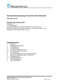
Operating Instructions andReference <strong>Manual</strong><strong>LMF</strong>4 Operational ControlsThere is a distinction to be made between the operational controls, displays and interfaces of thecontroller and the additional operational controls, displays and interfaces of an application whichaccommodates a controller. The function of the operational controls and displays of the controller isindependent of being used for a primary installation in a control box as a switchboard installationdevice, or of being integrated in an application with an own case.The number and type of the additional operational controls, displays and interfaces as well as theversion of the case corresponds with the respective customer requirements and , hence, isdocumented in the part of the documentation specific for application. Hence, only one example can beshown at this point.4.1 Front panel operational controls of Controller S320Controller S320 with its display lines and buttons is the core-piece of the <strong>LMF</strong>.Display linesEach of the three display lines consists of a 6-figure display for numerical values and a smaller 4-figure display for text. This text usually indicates the measuring circuit, unit or a designation of themeasurement value. In applications with two measuring circuits the first line is usually allocated to thefirst measuring circuit, and the second one to the second measuring circuit.<strong>LMF</strong> <strong>V5</strong>.8 Page 13
Operating Instructions andReference <strong>Manual</strong><strong>LMF</strong>ButtonsButton MeaningF1 Short keystroke in the standard mode:Scrolling of different measurement values and operands of measuring circuit 0.Short keystroke in the test mode:Scrolling of different measurement values or analog initial values of all measuringcircuits.Long keystroke in the standard mode:Switching over to he editing mode.Short keystroke in the editing mode:Display next parameter.F2Keeping F3 simultaneously pressed:Return to the standard mode again, but changes will be rejected.Short keystroke in the standard mode:Scrolling of different measurement values and operands of measuring circuit 1.Short keystroke in the test mode:Reduction of the displayed places in the second display line (raw value).F3Long keystroke:Return to the standard mode again, but changes will be taken over.Long keystroke in the standard mode:Switching over to the test mode.Short keystroke in the editing mode:Display previous parameter.ArrowleftArrowrightKeeping F1 simultaneously pressed:Return to the standard mode again, but changes will be rejected.In the test mode on inputs:Restores the factory settings of the sensor after nullification.Reducing of an analog initial value (provided it is just displayed).Otherwise: Reduces the displayed value (provided it can be edited).Long keystroke in the test mode:Nullification of the displayed measurement value.Otherwise: Raises the displayed value (provided it can be edited).Page 14 <strong>LMF</strong> <strong>V5</strong>.8
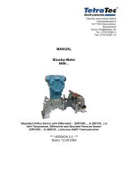
Operating Instructions andReference <strong>Manual</strong><strong>LMF</strong>4.2 Interfaces of Controller S320Interfaces of the controller(Example, assembly with interface cards, specific for order)Slots for interface cardsThe controller is equipped with 5 slots for interface cards. The designation of the slots is imprinted.The slots are marked with „Slot 0“ to „Slot 4“ from the left to the right. The interface cards for analogdigitalconversion (and vice versa) usually operate two analog devices each (sensors or actors), i.e.,they usually have 2 ports. The upper port has the designation „Port0“, the lower one „Port1“. If cablesare provided for the connection of the analogous devices, the connectors wear an adhesive label withan abbreviation for the indication of slot and port according to the pattern „Sl/“.Example: „Sl3/1“ stands for slot 3, port 1, this means the fourth column below.Integrated digital contacts8 outputs and inputs are available in each case, which are normally used for additional operationalcontrols as, e.g., buttons and their lighting. As integrated digital contacts they are not isolated byoptoelectronic coupler. If isolated or additional digital contacts are required, digital expansion modulesare required which can be activated by a type 400 card.Carrying capacity of each connection max. 24V/500mASupplyPower supply of the controller.From the left to the right: 0V, PE, 24VLinkSerial program interface. Connection of a laptop or PC with a serial 1:1 cable (9-pole). It is used by theS320 terminal program to transfer, e.g., the control program, the operating system or the configurationfile.Ser0Serial RS232 interface for the exchange of ASCII data, e.g., for the query or changing of parameters,for the query of measurement values or for remote control commands.Ser1Serial RS485 interfaces, is normally used fort he interlinking of several controllers.Ser2Serial RS485 interfaces, is normally used for the connection of serial sensors.Eth0Ethernet interface (TCP/IP).<strong>LMF</strong> <strong>V5</strong>.8 Page 15
Operating Instructions andReference <strong>Manual</strong><strong>LMF</strong>4.3 Additional front panel operational controls with installation in a recumbent 19“ cabinetNote:It only can be an example here. The real application may have less or more operational controls or theoperational controls may look differently. Completely different cases can be used, even severalcontrollers S320 can be accommodated in one case. The display corresponds with the most currentconfiguration.<strong>LMF</strong> front side (example)ButtonsButton MeaningPOWER For turning on and off of the device (main switch must be turned on). POWERseparates the device not completely from the power grid; in addition the mainswitch (usually on the back side) must be used or the mains plug must beremoved.START Starts, e.g., a mean taking measurement according to the application.STOPLEAKTESTQuits a started application prematurely (e.g. a mean taking measurement or aleak test).Quits the display of the results after untimely or automatic abnormal terminationof a measurement.Moreover, it is equivalent to the keyboard shortcut „F1+F3“ in the controller, i.e.,for returning from the test mode or editing mode to the standard mode.Starts a leak test (optionally).ZEROStarts a nullification of the sensors released for that. Identical function as remotecontrol command „ZERO“.Page 16 <strong>LMF</strong> <strong>V5</strong>.8
4.4 Back side interfaces with installation in a recumbent 19“ cabinetOperating Instructions andReference <strong>Manual</strong><strong>LMF</strong>Note:It only can be an example here. The real application may have another number and other types ofinterfaces. The interfaces can be partly arranged differently. In addition, pneumatic interfaces are alsopossible. Completely different cases can be used. The display corresponds with a largely equippedconfiguration.<strong>LMF</strong> back side (example)Interfaces of the example from the left to the rightMains connection With main switch, fuse holder, fan and nameplate (serial number).The main switch separates the device bipolar from the power grid. Before apower cord is connected, compare the indication of the voltage on the nameplate with the local mains voltage.Digital interfaces Opto-isolated interfaces for digital inputs and outputs, alternatively suppliedinternally or externally. According to the type of the digital expansion module 16outputs, 16 inputs, or 8 outputs and 8 inputs are available.Digital interfaces of this kind are used, e.g., for the connection of a manualremote control, for the activation of valves, etc., or fort he analysis of switches,or they are part of a PLC interface, which, e.g., can be lead out as 39 or 40 poleconnector with the installation in an IP54 protective case.Serial interfaces Here the serial interfaces and the Ethernet interface of the controller are leadoutside. The RS485 interfaces are additionally terminated.The serial interfaces can also be installed on the front panel, if required, but willnot be available on the backside any more than.Analog outputs Analog outputs are indicated by the designation „AO“. They are used, e.g., asan analog measurement value output or fort he activation of actuators with ananalog input signal, e.g. of servo valves.Analog inputs Analog inputs are indicated by the designation „AI“. They are required for theconnection of external analog sensors.<strong>LMF</strong> <strong>V5</strong>.8 Page 17
Operating Instructions andReference <strong>Manual</strong><strong>LMF</strong>5 Interfaces for Remote ControlThe Controller S320 included in the <strong>LMF</strong> uses two logical interfaces (“Link“ and “Comm“) for thecommunication with terminal programs.The interface “Comm“ allows a complete remote control. It is possible to query and changeparameters, query information or trigger actions. The command HELP displays an overview of theavailable commands. Any commercial terminal program can be used for that (ASCII mode), e.g., theterminal program Telnet which is included in the scope of supply with Microsoft Windows.The interface “Link“ supports the additional options of the terminal program S 320 provided with theCD for programming and start of operation.Physically the connection with these interfaces can be established by the Ethernet connection(TCP/IP) or both RS232 connections. The RS232 connection for the interface “Comm“ is normallyindicated as „serial“.If the Ethernet connection is used, both interfaces “ Comm“ and “Link“ are identified by the IP addressof the controller and different port numbers.Exampletelnet IP address and port numbers can be set with the interface “Link“ by using the appropriate RS232connection for this purpose.Notes• The RS485 connections are for a cross linking of several controllers or for the connection of serialsensors in one device. As a final user you normally are not faced with that, except with Commcommands with a RS232 connection, where the device address must be prefixed.• In special cases only the required connections are lead through possibly.5.1 Set up RS232 interfaceThe serial interface is preset, the settings can be seen in the configuration file. However, the settingsare also accessible as a parameter, i.e., they may be changed with the front panel operational controlsor with an existing serial connection.5.1.1 Default settings in the configuration file:Baud rate:The transmission rate of the RS 232 interfaceDefault setting: 9600 Bauds.Parity:Setting of the parity bit.Default setting: NONE (no parity bit)Stop bits:Number of stop bits of the RS 232 transmitterDefault setting: 1 stop bit(the receiver is always set to 1 stop bit)Handshake:Setting of the handshake process:Default setting: noneneither RTS/CTS (only hardware handshake),nor XON/XOFF (software handshake)Other settings are possible, if requested.The settings are saved in the parameters S0006 to S0009, see chapter 9.7.1Page 18 <strong>LMF</strong> <strong>V5</strong>.8
5.1.2 Interface settings in the terminal programOperating Instructions andReference <strong>Manual</strong><strong>LMF</strong>If the terminal program S320 is used, the entries will be saved, so it is not necessary to care about itafterwards. Open the menu „Connect“ and click on „Comm Settings“.The window „Global Settings“ appears with the opened tab „Comm“. Enter the interface you are using, e.g., „com1“, in the left field If you also want to use the link connection, please repeat the settings in the tab „Link“.NoteIf you want to use both interfaces at the same time, you will need a second Comm interface or a USBserial adapter. In this case you certainly enter this other serial interface of your computer in the tab„Link“. However, if you only have one interface or only one cable, you can use the interfacesalternately only. Enter this interface in both tabs then. Close the window „Global Settings“ with „OK“.5.1.3 Test function of the serial interface You will need a serial 1:1 cable with control wire with a 9-pole D Sub jack and a 9-pole D Subconnector (included in delivery). Connect the serial interface of the <strong>LMF</strong> with the serial interface of your computer. If you use a general terminal program, establish the connection with the serial interface of yourcomputer.- or - If you use the terminal program S320, change to tab „CommMsg“ and click on the button „ConnectComm“ in the launch-pad.Press the enter key of your computer.The connection works properly if you receive the response „Press help for details“.5.1.4 Test function of the link interfaceYou will need a computer with the installed terminal program S320 if you want to connect an OEM controller directly: a provided link cable- or - if you want to connect a <strong>LMF</strong> with protective case: a serial 1:1 cable with control wire with a 9-poleD Sub jack and a 9-pole D Sub connector (included in delivery). Connect the link interface of the <strong>LMF</strong> with the serial interface of your computer. Click on „Connect Link“ in the Launch-pad of the terminal program S 320.The connection works properly if the successful setup of the link connection is displayed in thefooter of the terminal program.5.2 Set up network interfaceYou will need a computer with the installed terminal program S320 a working link connection a released IP address5.2.1 Enter IP addressTip:Consult your network administrator for the assignment of the IP address. He can also assign amemorable computer name to the address what makes the access more comfortable later.Make sure that the option „Network enabled“ is active.To open the input mask for the IP address, click on the entry „Network Configuration“ in the menu„System“.Overwrite the Default IP address and customize the Netmask, if necessary.5.2.2 Adjust port numberIt is advisable to maintain the default port number. It is user-designed and it is saved in the parameterS0020. You can read and overwrite this parameter like any other parameter.<strong>LMF</strong> <strong>V5</strong>.8 Page 19
Operating Instructions andReference <strong>Manual</strong><strong>LMF</strong>5.2.3 Set IP address and port number in the terminal programThe terminal program must know the IP address (or, instead, the name of the computer of the <strong>LMF</strong>)and the port number. With Telnet these entries are attached simply at the end with the programrequest by command.If the terminal program S320 is used, the entries will be saved, so it is not necessary to care about itafterwards. Open the menu „Connect“ and click on „Comm Settings“.The window „Global Settings“ appears with the opened tab „Comm“. Enter the IP address or the computer name of the <strong>LMF</strong> and the port number in the right field. If you also want to use the link connection, repeat the settings in the tab „Link“. Close the window „Global Settings“ with „OK“.5.2.4 Test connection If a general terminal program is used, establish the connection by IP address and port number.- or - If the terminal program S320 is used, change to tab „CommMsg“ and click on the button „ConnectComm“ in the launch-pad.Press the enter key of your computer.The connection works properly if you receive the response „Press help for details“.5.2.5 Restrictions of accessBy using a network there will be the problem that there are clearly more computers by which anaccess is possible compared to the access of other interfaces (e.g., RS232). Normally physical accessto the device is not necessary any more. Even access by Internet is possible, for example.To limit the number of computers, by which an access is possible, two string parameters with accesslists exist for each network connection. These two string parameters are indicated as „Allow“ and„Deny“ for the following explanation. Each of these parameters contain an access list for the particularconnection, e.g.S00 Allowfor COMM connection by TCPS0021 DenyS9308S9309AllowDenyfor protocol printout, if S9300=8 (passive output by TCP)S9501 Allowfor virtual inputs and outputsS9502 DenyBasic principles of the TCP/IP network protocol are necessary for the understanding of the accesslists.The following is valid, in principle: Only accesses of IP numbers or computer names can beconfigured. An access is allowed if and only if the Allow list allows access or if the Deny list does notdeny it. If both lists are used, the Allow list has higher priority.Each of both string parameters may contain a list of IP numbers, or computer names as a substitute.The use of computer names only works properly if a valid DNS server is entered in the networkconfiguration of the controller, which can break down the used computer names. In addition, for eachspecification the entry of a net mask is still possible. Several computers are separated by semicolons,the (optional) net mask is separated by a slash. A preceding exclamation mark negates thecomparison.Examples for the syntax of the access lists:# A computer specified by its IP number192.168.28.13# Other display with explicit net mask192.168.28.13/32Page 20 <strong>LMF</strong> <strong>V5</strong>.8
# A computer specified by the namefrodo.example.orgOperating Instructions andReference <strong>Manual</strong><strong>LMF</strong># A complete class C network192.168.28.0/24# All computers except a class C network!192.168.28.0/24# Two computers192.168.28.13;192.168.28.55# Two computers and one class C network192.168.28.13;frodo.example.org;192.168.0.0/24Examples for the use of the access listsTo allow access by the com connection for exactly one single computer, this computer must beincluded in the suitable Allow list. The corresponding Deny list must include all the other computers:S00=192.168.28.13S0021=0.0.0.0/0#Allow list for COMM connection#Deny list for COMM connectionAn alternative configuration is possible with the help of the negation operator:S00=””# Allow list is emptyS0021=!192.168.28.13 # Deny list includes all computers but oneAccess for a local network, as well as for another computer:S00=192.168.28.0/24;myhost.lan # Allow listS0021=0.0.0.0/0# Deny listAccess for all computers with the exception of computer public.example.org:S00=””# Allow list is emptyS0021=public.example.org # Deny listThe examples are also applicable for the other type of connections mentioned above.<strong>LMF</strong> <strong>V5</strong>.8 Page 21
Operating Instructions andReference <strong>Manual</strong><strong>LMF</strong>5.3 Query and change of parametersNoteWhile the <strong>LMF</strong> is in the editing mode, no values can be changed by the interface “Comm“. If valueshave been changed by the interface “Comm“, which still have not been acknowledged by „EXIT“ or„SAVE“, these values cannot be changed in the editing mode using the keyboard.5.3.1 Physical unitsMany of the parameters represent physical values. If, in addition, there are several units (e.g., PSI andmbar as an unit for pressure), the unit can be selected in the editing mode. However, this does notapply for a query or change by remote control. Here the indication of the units is abandoned. This iswhy the values are always applied in SI units. The only exception: mA is used instead of ampere.Hence, with the input of a parameter value the previous conversion to SI units (with the exception mAinstead of A) has to be regarded. The input of physical units is not allowed.5.3.2 Query parametersAny parameter may be queried by simply entering its name. A list of parameters may be queried byreplacing single digits in the name by the question mark.Example:p000?Output of the controller:P0000=0P0001=1P0003=2P0004=1If parameters have been changed, but none of the commands TEMP or SAVE have been used up tonow to make effective the parameters, the currently valid value, followed by a ‚#’ sign, and the newvalue will be displayed.Example:p0000Output of the controller:P0000=0 # 15.3.2.1 Query measurement values and arithmetic valuesThe measurement values and arithmetic values are saved in the R parameters. They can be queriedas well as any other parameter.In addition, there is the option to use the command „RPAR“ which makes available substantially moreinformation.See also chapter 5.5.29.NoteThe R parameters belong to the parameters which cannot be changed.5.3.3 Change parametersMost parameters can be changed by entering an equals sign and a value after the parameter name.Example:P0000=0Output of the controller:P0000=0Page 22 <strong>LMF</strong> <strong>V5</strong>.8
Operating Instructions andReference <strong>Manual</strong><strong>LMF</strong>For the syntax of the indicated value see chapter 6.1The allocated value must be within the valid limits of the respective parameter, otherwise „RangeError“ will be returned. Some parameters are only readable („Read-only“), trying to change them willresult in the message „Access denied“ then.Parameters which have been changed will not become effective immediately, but only if, in addition,TEMP or SAVE is entered.Error messages with the entering of valuesConversion not possible Appears if the number cannot be converted into the demanded figureformat.No matchAppears if an input is recognized as a parameter, but this parameter doesnot exist in the present configuration.Value below minimum! Appears if a value shall be allocated to a parameter which is below actualvalue range.Value exceeds maximum! Appears if a value shall be allocated to a parameter which is below actualvalue range.Illegal CommandAppears if the input is not recognized as a command.<strong>LMF</strong> <strong>V5</strong>.8 Page 23
Operating Instructions andReference <strong>Manual</strong><strong>LMF</strong>5.4 Virtual inputs and outputsIn addition to really existing digital inputs and outputs the application <strong>LMF</strong> also knows virtual oneswhich can be queried or set by a separate network interface.The basic parameters for the connection are set in the parameter block S9500. The expressions whichdetermine the values of the virtual outputs are in the parameter block S1300. Within controlexpressions the value of a virtual input can be read with the function NI.Further information• Control expressions see chapter 6.3• Parameter block S1300 see chapter 9.7.6• Parameter block S9500 see chapter 9.7.285.4.1 CommunicationFor communication with a remote station the system waits for an external starting of connection. Onlyone connection is possible at a time. The communication is carried out with readable (ASCII) strings,single lines are terminated with „Carriage Return“ and „Line Feed“. The system understands thefollowing messages:QUITNI numberQUIT quits the connection. With NI the system is informed of a change of the input signals. Each bit ofthe number indicated as a parameter corresponds to an input. The following figure formats areallowed:• decimal: [0-9]+• decimal: [0-9]+d• hexadecimal: [0-9a-fA-F]+h• dual; %[01]+• octal: &[0-7]+• hexadecimal: $[0-9a-fA-F]+On the other hand, the controller also announces any change of the virtual outputs by this connection.The format in which the data are sent with a change of the outputs is configurable with parameterS9507. The definition of the format corresponds with the format used with the protocol pressure(S93XX), except that exactly one single integer argument is available, namely the current output state.The initial state is sent by the controller once immediately after the connection has been set up so thatthe remote station knows the initial state.Further information• Format strings see chapter 6.25.4.2 TimeoutsConnection errors (e.g. pulled network cable) may, for technical reasons, only be noticed if bothsystems exchange data. To make sure that such errors do not remain unnoticed, the configuration oftimeouts is possible (and recommended).If a reception time-out is configured, then the <strong>LMF</strong> assumes an error, if no command was received bythe remote station for longer than the set time. The existing connection is cancelled and the systemwaits for a new connection. Attention: If a reception time-out is configured, the remote station musttransmit data at regular intervals, otherwise the connection will be cancelled.If a transmission time-out is configured, then the <strong>LMF</strong> itself sends data at least in configured intervals.Since the state of the outputs is ordinarily only transmitted if something has been changed, the currentstate will even be transmitted in the case of a transmission time-out if the time-out has run off.A value of 0 for the respective time-out parameter switches off the time-out process.Page 24 <strong>LMF</strong> <strong>V5</strong>.8
5.4.3 Access controlOperating Instructions andReference <strong>Manual</strong><strong>LMF</strong>Two other parameters permit the restriction of the access to the interface. See also chapter 5.2.5.<strong>LMF</strong> <strong>V5</strong>.8 Page 25
Operating Instructions andReference <strong>Manual</strong><strong>LMF</strong>5.5 List of the remote control commands of the COMM interfaceNoteThe remote control commands will be valid no matter by which physical interface the logical COMMinterface has been built up. If the RS485 interface has been used, the device address must precedethe remote control commands.5.5.1 CONTROLThe command CONTROL displays the parameters for a regulator. Two arguments are expected: Thenumber of the program and the number of the regulator in the program (0 or 1).Example:control 0 0----- Control #0/0 -----P0400 - Mode: 1 (manual)P0401 - Hot edit : FALSEP0402 - T1: +1.000000E-01P0403 - TD: +0.000000E+00P0404 - TI: +1.000000E+00P0405 - VP: +1.000000E+00P0406 - Cor lower limit: +0.000000E+00P0407 - Cor upper limit: +1.000000E+00P0411 - Actual value : R0000P0412 - ActV error mode: 0 (error)P0416 - Reset behavior : 0 (last value)P0417 - Fixed reset val: +0.000000E+00P0420 - SP scale enable: FALSEP0421 - SP input : -1 (fixed value)P0422 - Fixed SP : +0.000000E+00P0425 - SP ramp : 0 (disabled)P0430 - Lin method : 0 (none)P0441 - SP disp unit : 1 (%)P0442 - SP disp digits : 3The parameter number precedes the output of the single parameters in each case. Inactiveparameters are not displayed.In addition to the output of the regulator data the command also sets the active regulator for thecommands CTD, CTI and CVP (see there).5.5.2 CTDUsing the command CTD the D portion of a regulator can be changed. In contrast to the allocation tothe parameter the CTD command changes the D portion with running regulator.The active regulator is the one which has been responded by the command CONTROL at last.5.5.3 CTIThe I portion of a regulator can be changed by the command CTI. In contrast to the allocation to theparameter the command CTI changes the D portion with running regulator.The active regulator is the one which has been responded by the command CONTROL at last.5.5.4 CVPThe V portion of a regulator can be changed by the command CVP. In contrast to the allocation to theparameter the command CVP changes the V portion with running regulator.The active regulator is the one which has been responded by the command CONTROL at last.Page 26 <strong>LMF</strong> <strong>V5</strong>.8
5.5.5 DATEOperating Instructions andReference <strong>Manual</strong><strong>LMF</strong>The command DATE queries date and time of the controller, or sets them. Invoking withoutparameters returns the current values. Invoking with the entry of time and date as an argument setsthe clock to the indicated value. The argument must have the format „dd.mm.yyyy hh:mm:ss“. Thetime will be saved fail-safe.5.5.6 DEFAULTSAll parameters can be reset to the delivery state by the command DEFAULTS. The program requestsfor a second input for user settings not being deleted by mistake.Example:defaultsOutput of the controller:Please enter: "DEFAULTS 4c6a" within 15 secondsInput:defaults 4c6aOutput of the controller:DEFAULTS: OK - will reboot in a momentAfter having established the delivery state the device will be started again, so that changes becomeeffective. With the first start the reset must be confirmed on the controller by pressing F1 additionally.5.5.7 DISCARDDISCARD discards all parameter changes, which have not yet been taken over by TEMP or SAVE.5.5.8 DLISTThe command DLIST displays a display list. A numerical argument (the number of the desired displaylist) is expected.Example:dlist 0Output of the controller:--------- Display list 0 ---------D0100 - Pages in list : 11D0101 - Mode: 1 (row mode)D0102 - Page #0 : 1D0103 - Page #1 : 11D0104 - Page #2 : 12D0105 - Page #3 : 13D0106 - Page #4 : 14D0107 - Page #5 : 15D0108 - Page #6 : 16D0109 - Page #7 : 17D0110 - Page #8 : 18D0111 - Page #9 : 19D0112 - Page #10 : 20The parameter number precedes the output of the single parameters in each case. Inactiveparameters are not displayed.<strong>LMF</strong> <strong>V5</strong>.8 Page 27
Operating Instructions andReference <strong>Manual</strong><strong>LMF</strong>5.5.9 DMODEDMODE displays an overview of the display lists used in the different modes.Example:dmodeOutput of the controller:--------- Display mode mapping ---------Mode 0 (Conti): 0Mode 1 (Poll): 1Mode 2 (Meas): 2Mode 3 (Fill): 3Mode 4 (Calm): 4Mode 5 (Cal): 1Mode 6 (Vent): 1Mode 7 (Wait): 1Mode 8 (MeasResult): 1Mode 9 (Zero): 0Mode 10 (Leak): 0Mode 11 (LeakResult): 05.5.10 DPAGEWith DPAGE single display pages can be displayed.Example:dpage 3Output of the controller:--------- Display page 3 ---------D1030 - Upper row : 10800 (R parameter in P0800)D1031 - Middle row : 10801 (R parameter in P0801)D1032 - Bottom row : 196 (R0196)5.5.11 EDITMENUThe command EDITMENU starts the editing menu of the controller and corresponds with the keyboardshortcut “ F1 (long) ” there.5.5.12 EVALWith EVAL expressions can be tested as they are used in the parameter blocks S14XX or S18XX, forexample.Example:eval meas & (measmode = 1)Output of the controller:meas & (measmode = 1) => Integer (0)The command EVAL can also be used as a small electronic calculator.Example:eval 2.0 * 3.14Output of the controller:2.0 * 3.14 => Float (+6.280000E+00)5.5.13 FACDBGFACDBG serves for the control of debugging displays and it is not provided for being used by the finaluser.Page 28 <strong>LMF</strong> <strong>V5</strong>.8
5.5.14 GASMIXOperating Instructions andReference <strong>Manual</strong><strong>LMF</strong>The command GASMIX displays information of a gas mixture. As a parameter the number of the gasmixture (0 .. 9) has to be indicated.Example:gasmix 0Output of the controller:----- GasMix #0 -----M0000 - Name : "Gas mix 0"M0001 - Count : 2M0010 - 0. Gas: 1 (Air)M0011 - 0. Frac : +5.000000E+01M0015 - 1. Gas: 14 (N2O)M0016 - 1. Frac : +5.000000E+01The parameter number precedes the output of the single parameters in each case. Inactiveparameters are not displayed.5.5.15 HELPHELP displays a short overview of the available commands.Example:helpOutput of the controller:CONTROL prog cQuery controller dataCTD valSet TD for a controllerCTI valSet TI for a controllerCVP valSet VP for a controllerDATE [date/time] Display or set time and dateFormat is dd.mm.yyyy hh:mm:ssDEFAULTSReset to manufacturer settingsDISCARDDiscard modified parametersDLIST nShow display list nDMODEPrint display mode mappingDPAGE pShow display page pEDITMENU Enter the edit menu (hold F1)EVALEvaluate an expressionFACDBGEnable/disable debug facilitiesGASMIX nDisplay gasmix dataHELPPrint command descriptionsINPUT nDisplay analog input dataIVALVE nDisplay impulse valve dataLASTSTATESPrint last statesLEAKStart the leak testLOGLEVELSet the log levelMEASStart measurementOUTPUT nDisplay analog output dataPORTMAP port prog Display analog output port mappingPRIMARY nDisplay primary element dataPROG [sec prog]Query or set the running programPROGMENU Enter the prog menu (hold F2)QUITTerminate the network connectionRPAR nDisplay read parameter nSAVESave parametersSCRIPTINFOScript interpreter infoSISENDSend a command to a serial sensorSTOPStop measurement/soft resetTEMPUse modified parametersTESTMENU Enter the test menu (hold F3)<strong>LMF</strong> <strong>V5</strong>.8 Page 29
Operating Instructions andReference <strong>Manual</strong><strong>LMF</strong>TIMESTATPrint time statisticsVERSPrint the software version numberZEROZero inputsparam Query parameter value (i.e. P1234)param=valueSet parameter (i.e. P1234=1)5.5.16 INPUTINPUT displays information about an analog input. The number of the input (0 to 19) has to beindicated as a parameter. The data correspond with the parameters of an input of the S-parameterblock S2XXX / S3XXX.Example:input 0Output of the controller:----- Input #0 -----S2000 - Type: 0 (internal AI)S2001 - Lin method : 0 (Polynom)S2005 - Lin poly order : 1S2010 - Lin factor #0 : -7.500000E+02S2011 - Lin factor #1 : +1.875000E+02S2020 - Lin X factor : +1.000000E+00S2021 - Lin Y factor : +1.000000E+00S2022 - Serial number : ""S2030 - Offs: +0.000000E+00S2031 - Offs method : 0 (before linearization)S2032 - Zero input : 0 (no)S2033 - Zero timeout : +0.000000E+00S2034 - Zero group : 0S2035 - 4 mA Check : TRUES2036 - Range check : 0 (no)S2039 - Damping : 1S2050 - Port number : 0The parameter number precedes the output of the single parameters in each case. Inactiveparameters are not displayed.5.5.17 IVALVEThe command IVALVE displays information about an impulse valve. The number of the impulse valve(0 .. 9) has to be indicated as a parameter. The data correspond to a block of the parameter rangeS16XX.Example:ivalve 0Output of the controller:----- IValve #0 -----S1600 - Open port : 4S1601 - Close port : 5S1602 - State expr : "(STATE >= 2400) && (STATE < 2500)"The parameter number precedes the output of the single parameters in each case. Inactiveparameters are not displayed.5.5.18 IZEROIZERO zeros a single input. The number of the input must be entered as a parameter. The commandis only permissible in the standard mode. A feedback is carried out only with severe syntax errors ofthe input.Example:izero 0Page 30 <strong>LMF</strong> <strong>V5</strong>.8
5.5.19 LASTSTATESOperating Instructions andReference <strong>Manual</strong><strong>LMF</strong>With LASTSTATES a list of the last 10 internal states can be displayed. This command is applicablesensefully only for troubleshooting and for developer purposes, and it should be used only byspecialist staff.5.5.20 LEAKThe command LEAK starts a leak testing. If the measuring section is equipped accordingly, shut-offvalves are closed on the inputs and outputs of the measuring section and the pressure change will bemeasured for a configurable time.5.5.21 LOGLEVELThe output of messages can be queried or influenced by the command LOGLEVEL. This command isapplicable sensefully only for troubleshooting and for developer purposes, and it should be used onlyby specialist staff.5.5.22 MEASThe command MEAS starts a mean-taking measurement.5.5.23 OUTPUTOUTPUT displays information about an analog output. The number of the output (0 .. 9) has to beindicated as a parameter. The data correspond to the parameters of an output of the S-parameterblock S8XXX.Example:output 0Output of the controller:----- Output #0 -----S8000 - Type: 0 (internal AO)S8001 - Lin method : 0 (Polynom)S8005 - Lin poly order : 1S8010 - Lin factor #0 : +0.000000E+00S8011 - Lin factor #1 : +1.000000E+00S8020 - Lin X factor : +1.000000E+00S8021 - Lin Y factor : +1.000000E+00S8022 - Serial number : ""S8050 - Port number : 0The parameter number precedes the output of the single parameters in each case. Inactiveparameters are not displayed.5.5.24 PORTMAPThe command PORTMAP displays information about the allocation of a R parameter to an output. Thenumber of the table entry and the program are expected as a parameter. The data correspond to theparameters of the P-parameter block PX9XX.Example:portmap 0 0Output of the controller:----- PortMap #0 -----P0900 - Port: 0 (S80XX)P0901 - R parameter : R0000P0902 - Output scale lo: +0.000000E+00P0903 - Output scale hi: +1.000000E+00P0904 - Error handling : 1 (use fixed value)P0905 - Error value : +0.000000E+00<strong>LMF</strong> <strong>V5</strong>.8 Page 31
Operating Instructions andReference <strong>Manual</strong><strong>LMF</strong>The parameter number precedes the output of the single parameters in each case. Inactiveparameters are not displayed.5.5.25 PRIMARYThe command PRIMARY displays information about a primary element. The number of the primaryelement (0 .. 139) has to be indicated as a parameter. The data correspond to the parameters of aprimary element of the parameter blocks S4XXX/S5XXX/S6XXX/S7XXX or EXXXX.Example:primary 1Output of the controller:----- Primary #1 -----S4100 - Type: 0 (standard LFE)S4101 - Cal gas : 1 (Air)S4102 - Cal pressure : +1.013207E+05S4103 - Cal temperature: +2.942610E+02S4104 - Cal humidity : +0.000000E+00S4105 - Lin poly order : 3S4110 - Lin factor #0 : +0.000000E+00S4111 - Lin factor #1 : +5.536489E-04S4112 - Lin factor #2 : -5.144490E-07S4113 - Lin factor #3 : +0.000000E+00S4120 - Lin X factor : +1.000000E-02S4121 - Lin Y factor : +6.000000E+04S4122 - Serial number : "752970-J9"The parameter number precedes the output of the single parameters in each case. Inactiveparameters are not displayed.5.5.26 PROGThe command PROG is used to query or change the currently running program. The command alwaysneeds the number of a measuring circuit as an argument. If only the measuring circuit is indicated,then the program running in this measuring circuit will be displayed. If, in addition, a program numberis indicated, then there will be a change to this program.The command PROG only changes the currently running program. The running program is takenagain from the parameter S100X with a soft reset (e.g., after entering TEMP), or with a restart.5.5.27 PROGMENUThe command PROGMENU invokes the program menu of the controller. The command correspondsto the keyboard shortcut „ F2 (long) “.5.5.28 QUITQUIT quits an existing network connection.5.5.29 RPARThe command RPAR displays information about a R parameter. In contrast to a query via RXXXX notonly the value of the parameter is available, but also additional information, as for example the errorcode. The command needs the number of the R parameter as an argument.Example:rpar 1Page 32 <strong>LMF</strong> <strong>V5</strong>.8
Output of the controller:----- R0001 -----Error = OKVal = +8.548035E+00 PaValDisp = 0.085 mbarDigits = 3= +8.548035E-02 mbarUnit = 3Desc = "Pdif\4U"Operating Instructions andReference <strong>Manual</strong><strong>LMF</strong>The first value with the designation „Val“ is the value in SI units. The second one is the same valueconverted to the respective display unit. „Disp“ is the value which is displayed on the controller display.„Digits“ and „Unit“ are post comma places and unit.5.5.30 SAVESAVE saves changes of parameters fail-safe. It has to be made sure that during the saving process(controller indicates SAVE in the right, upper display) the power supply is not interrupted.5.5.31 SCRIPTINFOSCRIPTINFO displays a list of the functions and variables applicable in expressions as a littlememory.Example:scriptinfoOutput of the controller:----- Script info -----Node heap utilization: 384/384Obj NameType--------------------------V FALSEINTV TRUEINTV CYCLEFLOATV CYCLECOUNT INTV NOKLOCKINTV MEASINTV MEASAVAIL INTV MEASMODE INTV MODEINTV STATEINTF PROGINTF RPARFLOATF DIINTF RESINT„V“ marks a variable and „F“ marks a function in the column „Obj“.5.5.32 SISENDBy SISEND commands can be sent with the RS485 bus to which serial sensors are connected. Thiscommand is applicable sensefully only for troubleshooting and for developer purposes, and it shouldbe used only by specialist staff.5.5.33 STOPQuits a started application prematurely (e.g., a measurement forming an average value or a densitytest).Quits the display of the results after untimely or automatic abnormal termination of a measurement.<strong>LMF</strong> <strong>V5</strong>.8 Page 33
Operating Instructions andReference <strong>Manual</strong><strong>LMF</strong>5.5.34 TEMPWith TEMP changes in parameters are temporarily taken over, i.e. up to the next restart of thecontroller.5.5.35 TESTMENUThe command TESTMENU invokes the test mode of the controller. The command corresponds to thekeyboard shortcut „F3 (long)“5.5.36 TIMESTATThe command TIMESTAT displays information about the time of the processing steps carried out inthe controller. The outputs can only be used sensefully by developers.5.5.37 VERSVERS displays the state of the software version and an internal release number.Example:versOutput of the controller:Software Version: 5.000SVN Revision: 854M5.5.38 ZEROThe sequence for the nullification of the sensors is started by the command ZERO. There all sensorswill be zeroed whose inputs are defined as zeroable. This property is saved in the parameters S2x32,where x stands for the number of the input.Depending on the equipment of the measuring section defined working conditions can be produced,e.g., by the switching of the valves which separate the pressure sensors from the measuring sectionand which produce a pressure equalization. Parameter block S1800 defines which valves areswitched in which operating conditions.Up to the achievement of a pressure equalization incl. thermalization a stabilization period isnecessary as a rule. Now it is possible to define up to three stabilization periods and up to threegroups of sensors which are zeroed at the end of the respective stabilization period at the same time.The stabilization periods are saved in the parameters S1100, S1101 and S1102.Each sensor input can be allocated to one of the groups. This allocation is saved in the parametersS2x34, where x stands for the number of the input again.Notes for the sequence• The stabilization periods should be selected in such a way that the assumption is right that thesensor will measure physically a zero value at the end of the stabilization period.• A real sensor will transmit a signal other than zero (offset). It now depends on the setting ofparameter S2x31 whether the offset will be calculated by the signal being really present at theinput (e.g., of a tension), or by the physical value calculated by the linearization polynomial. As arule the latter is to be preferred.• After all stabilization periods have been terminated and all sensor groups have been zeroed, theprevious operating conditions will be continued.• The offset values are not stored fail-safe. To reach this, the command SAVE must be transmittedadditionally. Nevertheless, this has to be used reluctantly, since the Flash ROM is not writeableinfinitely.• Each sensor can be aligned automatically regardless of remote control commands or functionkeys on the device in solid time intervals. The interval is saved in the parameter S2x33.For further information and notes to requirements of the nullification see chapter 7.4.3Fehler!Verweisquelle konnte nicht gefunden werden..Page 34 <strong>LMF</strong> <strong>V5</strong>.8
Operating Instructions andReference <strong>Manual</strong><strong>LMF</strong>6 SyntaxThis chapter includes the syntax of• figure formats for the input of numerical parameter values• format strings, e.g., for protocol print functions (see chapter 9.7.27)• control expressionsThe special syntax of access lists for network connections is documented at an appropriate place, seechapter 5.2.56.1 Figure formats for the input of numerical parameter valuesFigures in exponentnotationFigures in fixed-pointnotation#.#######E##±#.#######E±###.#######±#.#######Integers #######±#######Selection parameters #######±#######• Positive signs may be left out.• The number of digits of mantissa and exponent arevariable.• The values can be also entered in fixed-pointnotation.• A decimal comma instead of a decimal point is notpermissible.• Positive signs may be left out.• The number of the decimal and pre-comma placesis variable.• If queried the display appears in exponent notation• A decimal comma instead of a decimal point is notpermissible.• The number of the digits is variable.• Selection parameters differ from the type „integer“by the fact that only certain values are admitted.6.2 Format strings for protocol printout functionsThe format strings consist of a sequence of:• placeholders with format specification,• control characters, and• normal signs.The syntax %a$fw.ps is followed by a placeholder with format specification, where the following isvalid:• a is the number of the argument of S932X which should be inserted here.• f are single signs which influence the output:- +: An algebraic sign is also displayed with positive figures.- -: The output is done left-aligned within the field width.- !: The output is done concentric within the field width.- 0: In the case of right-aligned output the left side is filled in with zeros.• w is the total width in which the argument is formatted. w is optional.• p is the accuracy. For floating point figures (s = e, E or f) the accuracy is the number of thedecimal places. For integers (f = d) the accuracy is the number of the places. p is optional, if it isnot indicated, then the point in front of it must also be cancelled. If no accuracy is indicated, thenthe default will be 6 for floating point figures and 0 for integers.• s is the real format. ‚d’ is a decimal integer format‚ ‚x’ and ‚X’ are integers in the hexadecimalformat‚ ‚f’ is floating point without exponent, ‚e’ and‚ ‚E’ are floating point with exponent and aprecomma place in the mantissa.<strong>LMF</strong> <strong>V5</strong>.8 Page 35
Operating Instructions andReference <strong>Manual</strong><strong>LMF</strong>Control charactersControl characters are initiated with a backslash. The following control characters are available:• \t Tab character• \\ Backslash• \r Carriage Return• \n LinefeedNormal charactersAll characters not recognized as control characters or as a format specification are copied 1:1 in theoutput.Examples• „%2$d“ displays the value of S9322 as an integer: „42“.• „%2$0.4d“ displays the value of S9322 as an integer with 4 places and leading zeros: „0042“.• „ %2 $ + 0.4d “ displays the value of S9322 as an integer with 4 places, leading zeros and analgebraic sign even with positive figures: „+042“.• „ %2 $ + 010.4d “ displays the value of S9322 as an integer with 4 places, leading zeros, analgebraic sign even with positive figures, and a total width of 10 signs: „+042“.• „ %2 $-+ 010.4d “ displays the value of S9322 as an integer with 4 places, leading zeros, analgebraic sign even with positive figures, and a total width of 10 signs left-aligned: „+042“.• „%0 $.3f“ displays the value of S9320 as a floating point figure with 3 decimal places: „42.000“.• „%0$E“ displays the value of S9320 as a floating point figure with 6 decimal places:„4.200000E01“.• „%0 $.3e“ displays the value of S9320 as a floating point figure with 3 decimal places: „4.200E01“.All 4 strings (S9301-S9304) are displayed.6.3 Control expressionsTo be able to customize the device easier to different application scenarios, expressions are used atmany places for the determination of input or output signals. The calculation is carried out within theseexpressions and access to inputs or status variables used in the software is possible.6.3.1 Operators and their prioritiesOp Name Description PrioId Variable Values of the variable at the analysis time 0Id() Function All functions have exactly one parameter of the type INTEGER. 0The result can be of type INTEGER or FLOAT according to thefunction.() Clamping 0- Unary minus 0+ Unary plus 0! Unary Boole NOT Operand has to be of type INTEGER 0~ Unary NOT Operand has to be of type INTEGER 0_ Debug output The operator _ must be followed by an integer constant. During theanalysis of the expression the integer constant and the value of thefollowing partial expression will be displayed on the console. Thisallows for the test of more complex expressions.0* Multiplication Operands can be INTEGER or FLOAT. Result is of the same typeas of operand./ Division Operands can be INTEGER or FLOAT. Result is of the same typeas of operand.11Page 36 <strong>LMF</strong> <strong>V5</strong>.8
Operating Instructions andReference <strong>Manual</strong><strong>LMF</strong>\ Modulo Operands have to be of type INTEGER. 1& Binary AND Operands are INTEGER 1+ Addition Operands can be INTEGER or FLOAT. Result is of the same type 2as of operand.- Subtraction Operands can be INTEGER or FLOAT. Result is of the same type 2as of operand.| OR bit by bit Operands have to be of type INTEGER. 2^ XOR bit by bit Operands have to be of type INTEGER. 2= Equal Operates with INTEGER or FLOAT types as operands. The resultis an INTEGER with the value 0 or 1.!=, Unequal Operates with INTEGER or FLOAT types as operands. The resultis an INTEGER with the value 0 or 1.< Less than Operates with INTEGER or FLOAT types as operands. The resultis an INTEGER with the value 0 or 1.> More than Operates with INTEGER or FLOAT types as operands. The resultis an INTEGER with the value 0 or 1.>= More than or Operates with INTEGER or FLOAT types as operands. The resultequalis an INTEGER with the value 0 or 1.
Operating Instructions andReference <strong>Manual</strong><strong>LMF</strong>SPSIN1 INTEGER. State of the extension signal #1 (see S1412) when the main cyclestarts.SPSIN2 INTEGER. State of the extension signal #2 (see S1413) when the main cyclestarts.SPSLDET INTEGER. State of the input LDET (see S1409) when the main cycle starts.SPSLOCK INTEGER. TRUE if it waits for the error acknowledgement signal of the PLC.SPSMODE INTEGER. Program mode (corresponds to S0010).SPSREADY INTEGER. TRUE if the program waits for the START signal of the PLC.SPSVDET INTEGER. State of the input VDET (see S1410) when the main cycle starts.SPSZERO INTEGER. State of the input ZERO (see S1406) when the main cycle starts.STATE INTEGER. The state of the internal state machine.STAUTH INTEGER. Includes 1 during the password query, otherwise 0.STCAL INTEGER. Includes 1 during the calibration mode, otherwise 0.STCALM INTEGER. Includes 1 during the stabilization period, otherwise 0.STEDIT INTEGER. Includes 1 in the editing menu, otherwise 0.STFILL INTEGER. Includes 1 during the filling phase, otherwise 0.STLDET INTEGER. Includes 1 during the determination of the system leakage (LMS),otherwise 0.STMEAS INTEGER. Includes 1 during the measuring phase, otherwise 0.STPFIL INTEGER. Includes 1 during the prefilling period, otherwise 0.STPOLL INTEGER. Includes 1 during the polling phase, otherwise 0.STPROG INTEGER. Includes 1 in the program menu, otherwise 0.STSAVE INTEGER. Includes 1 during the saving, otherwise 0.STTEMP INTEGER. Includes 1 during the taking over of parameters, otherwise 0.STVDET INTEGER. Includes 1 during the determination of the test sample volume (LMS),otherwise 0.STVENT INTEGER. Includes 1 during the ventilation phase, otherwise 0.STWAIT INTEGER. Includes 1 during the waiting on PLC stop, otherwise 0.STZERO INTEGER. Includes 1 during the zero phase, otherwise 0.TRUE INTEGER constant. Always has the value 1.Table 2.VariablesNoteThe variables STxxx are set by the help of the state of the internal state machine and they do not onlycover the real operation, but also initializations and transitional states.6.3.3 FunctionsNameDIFFNIPROGRESRES0DescriptionReads a digital input. Result is an INTEGER. The current input value stands in bit0, bit 1 indicates whether a change of state has occurred in the last cycle. So0: Input is steady on OFF.1: Input is steady on ON.2: Input has changed from ON to OFF.3: Input has changed from OFF to ON.Supplies the initial value of a flip flop (see S12nn). The parameter for the function isthe number of the flip flop (0.. 9).Supplies the value of a virtual input. The bit definition corresponds to that of thefunction DI.Returns the program running in a measuring circuit.Returns the evaluation of the test in the respective measuring circuit. Functionresult: 1 = NOTAVAIL, 8 = FAIL, 16 = OK, 32 = NOK, 64 = OFF.Returns the individual value 0 of the test in the respective measuring circuit.Function result: 1 = NOTAVAIL, 2 = LOW, 4 = HIGH, 8 = FAIL, 16 = OK.Page 38 <strong>LMF</strong> <strong>V5</strong>.8
RES1RES2RES3RPARSP0SP1SP2SPSOKTable 3.FunctionsOperating Instructions andReference <strong>Manual</strong><strong>LMF</strong>Returns the individual value 1 of the test in the respective measuring circuit.Function result: 1 = NOTAVAIL, 2 = LOW, 4 = HIGH, 8 = FAIL, 16 = OK.Returns the individual value 2 of the test in the respective measuring circuit.Function result: 1 = NOTAVAIL, 2 = LOW, 4 = HIGH, 8 = FAIL, 16 = OK.Returns the individual value 3 of the test in the respective measuring circuit.Function result: 1 = NOTAVAIL, 2 = LOW, 4 = HIGH, 8 = FAIL, 16 = OK.Reads out a R parameter and supplies the current value. The result is of the typeFLOAT. Unknown R parameters or those with errors make 0.0.Returns the sub program in measuring circuit 0. The number of the sub programparameter set is the parameter.Returns the sub program in measuring circuit 1. The number of the sub programparameter set is the parameter.Returns the sub program in measuring circuit 2. The number of the sub programparameter set is the parameter.Returns TRUE if a test has been carried out in the measuring circuit and the resultis OK.The command SCRIPTINFO includes a memory of the available variables and functions.<strong>LMF</strong> <strong>V5</strong>.8 Page 39
Operating Instructions andReference <strong>Manual</strong><strong>LMF</strong>7 Operation modesThis chapter explains the most important operation modes except the PLC mode. The PLC operationmode is explained in an own chapter, see chapter 16.7.1 STANDARD MODEThe standard mode is the mode which is active after the switch-on. It is also active if one of the othermodes has been quit. As a rule the lower display line is used in the standard mode to display thecurrent measuring program. Nevertheless, this can be initialized and, hence, deviations are possible inthis item.All arithmetic values and measurement values are continuously displayed in the standard mode. Thedisplayed values can be toggled with the function keys „F1“, „F2“ and „F3“ starting from the default.The standard display setting is determined in the parameters and it can be changed in the editingmode.7.1.1 Program selectionThe <strong>LMF</strong> makes available up to 10 different measuring programs. They cannot be distinguished by thesoftware, but they are alternative parameter sets with which, e.g., different sensor sets or measuringranges are selected. To enter the program selection, press the function key „F2“ for approx. 3 seconds.The highest valid program number is displayed in the upper display line.The current program number is displayed in the middle display line, and the accompanyingmeasuring circuit is displayed on the right of it.The lowest valid program number is displayed in the lower display line. Select the desired measuring circuit using the function keys „F1“ and „F3“ (provided that morethan one measuring circuit exist). Select the desired program number using the function keys „“. To take over the changes with mains failure protection, press the function key „F2“ for 3 seconds.-or- To reject the changes, press the key „STOP“ or press the function keys „F1“ and „F2“ at the sametime for 3 seconds.7.2 LEAK TESTINGThis mode is intended as an accessory for the checking of the test section design for tightness.Leakage in the measuring system is the most frequent cause for faulty measurements and measuringdeviations. With this function the test sample and the reference device can be checked for leakage bythe pressure drop method.Fill the system with overpressure and vacuum and separate the pressure supply again.To activate the leakage test press the button "LEAK Test".The parameters S8001 to S8007 (cf. Table 32) determine the display options and the test period. Afterthe pressure drop measurement has been finished the measurement result appears on the LEDdisplays:P0: Pressure at the beginning of the leak testingP1: Pressure at the end of the leak testingPmin: the lowest pressure having appeared during the testPmax: the highest pressure having appeared during the testdpdt: Pressure gradient during the testThe calculation of the result is done by the equation:Initial pressure - final pressurePressure drop / rise per time =Measuring timeThe result is treated with correct signs. To quit the leak testing press the button „STOP“ or press the function keys „F1“ and „F2“ at thesame time and keep them pressed for 3 seconds.Page 40 <strong>LMF</strong> <strong>V5</strong>.8
7.3 MEASUREMENT by taking the meanOperating Instructions andReference <strong>Manual</strong><strong>LMF</strong> To start a measurement by taking the mean, press the button „START“, or transmit the command„MEAS“ by remote control.The <strong>LMF</strong> starts with the cyclic recording of the measurement values and computed values.During the measurement both upper display lines continue to display the current measurementvalues (can be configured). The measuring time is displayed in the lower display line.At the end of the measuring time the results are displayed. For any flow rate and sensor value theminimum values and maximum values are also displayed in addition to average. As long as theresults are displayed, the <strong>LMF</strong> carries out no measurements.NoteThe measurement can be finished prematurely by pressing the button „STOP“ or by pressing of thefunction keys „F1“ and „F3“ at the same time. Even in this case the results will also be displayed.To view the different averages of the sensor values and flow rates toggle them with the functionkey „F1“.To return to the standard mode again, press the button „STOP“ or press the function keys „F1“and F3 “ at the same time.Note:With double section devices the measurement values and results are marked, in addition, with 0 fordistance 0 and with 1 for distance 1. Limits as well as minima and maxima are always indicated withthe accompanying physical value.7.4 Special modes for the experienced user7.4.1 Test modeThe test mode is for looking at the input signals and for editing the output signals. By the simultaneousdisplay of the raw value and the value calculated out of it there is the possibility of a plausibility test. To activate the test mode, keep the function key „F3“ pressed for 3 seconds.In the upper display line the test mode is indicated.In the middle display line the current raw value of the input or output is indicated.In the lower display line the physical value calculated with the linearization polynomial is indicated. Select the desired input or output using the function keys „F1“ and „F3“.NoteOnly inputs which are active in the current program are displayed.If you have selected an input: Press function key „F2“ to change the number of the displayed digits.If you have selected an output: Set desired output signal using the arrow keys „“.NoteIn the test mode the arrow keys „“ have functions for the nullification of the inputs. Absolutelyfollow chapter 7.4.3 for this purpose! To take over the changes with mains failure protection, press the function key „F2“ for 3 seconds.-or- To reject the changes, press the key „STOP“ or press the function keys „F1“ and „F2“ at the sametime for 3 seconds.<strong>LMF</strong> <strong>V5</strong>.8 Page 41
Operating Instructions andReference <strong>Manual</strong><strong>LMF</strong>7.4.2 Controller modeThe <strong>LMF</strong> may include up to two active controllers at the same time per program. Each controller canbe switched in manual or automatic operation. The default mode of operation is determined in theparameters Px400 and Px450, but it can be switched. If the controller mode is activated, the lastsetting applies.7.4.2.1 Overview automatic operation and manual operationThe following settings are possible with automatic operation• Set value• Also the controller parameters T1, TD, TI and VP with activated option „Hotedit“ (parameter Px401or Px451).The new settings will become active immediately.The following settings are possible with manual operation• optionally set value or control value• the controller parameters T1, TD, TI and VPThe switching on and off of a controller is only possible with parameter Px400 or Px450.7.4.2.2 Activate controller mode and select controller Press both arrow keys „“ simultaneously and keep them pressed for 3 seconds.The controlled variables of the first controller are indicated in the three lines of the display. Theupper line displays the actual value, the middle line the set value and the lower line the controlvalue. To indicate the desired controller, scroll forward the function key „F1“ or scroll backward thefunction key „F3“.7.4.2.3 Adjust set valueThe controller set value is saved in parameter Px422 or Px472 and it can be changed in the controllermode using the arrow keys.Automatic operation Change the set value using the arrow keys „“.<strong>Manual</strong> operation If the point flashing on the right is in the lowest line, press the function key „F2“ for a shortmoment.The flashing point jumps to the middle line, i.e. now the set value can be edited. Change the set value using the arrow keys „“.7.4.2.4 Adjust control value (only manual operation) If the point flashing on the right is in the middle line, press the function key „F2“ for a shortmoment.The flashing point jumps to the lower line, i.e. now the control value can be edited. Change control value using the arrow keys „“.7.4.2.5 Switch mode of operation Press the arrow keys „“ simultaneously.The menu „Mode“ is indicated.The current mode is indicated. Change mode using one of the arrow keys „“.Now it is possible to leave the menu „Mode“ or immediately continue with the setting of the controllerparameters.Page 42 <strong>LMF</strong> <strong>V5</strong>.8
Operating Instructions andReference <strong>Manual</strong><strong>LMF</strong> To take over the change with mains failure protection, keep the function key „F2“ pressed for 3seconds.-or- To reject the change, press the key „STOP“ or press the function keys „F1“ and „F2“ at the sametime and keep them pressed for 3 seconds.7.4.2.6 Adjust controller parameterIf the menu „Mode“ is not already active, press the arrow keys „“ simultaneously.If the controller is in automatic operation, set the manual mode of operation with one of the arrowkeys.Scroll with function keys „F1“ or „F3“ to the menus „T1“, TD, TI or „VP“.The menus of the controller parameters indicate the value currently saved in the parameter in themiddle line (see table below). This value can be changed proportionally. The proportional applicationof this value is indicated in the lower line. Set percentage with arrow keys „“. To take over the changes, press the function key „F2“ for 3 seconds.The parameter will be overwritten with mains failure protection, i.e., with the next opening of themenu the value is changed, and the lower line is set to 100% again. To reject the changes, press the key „STOP“ or press the function keys „F1“ and „F2“ at the sametime for 3 seconds.Overview of the controller parameters:T1 Px402 Px452 Time constantTD Px403 Px453 Differential shareTI Px404 Px454 Integral shareVP Px405 Px455 Loop gain7.4.2.7 Leave controller mode To take over changes of the set value and control value, press the function key "F2" for 3 seconds.The changes are valid up to the next switching off or restart of the software (no saving with mainsfailure protection)-or- To reject the changes of the set value and control value, press the key „STOP“ or press thefunction keys „F1“ and „F2“ at the same time and keep them pressed for 3 seconds.<strong>LMF</strong> <strong>V5</strong>.8 Page 43
Operating Instructions andReference <strong>Manual</strong><strong>LMF</strong>7.4.3 NullificationSince the differential pressure sensors and relative pressure sensors may be dependent on position, anullification must always be carried out when changing the place of installation for the differentialpressure sensors or relative pressure sensors.In addition, the nullification should be carried out in regular time intervals to compensate long-termdrifts of the sensors.The nullification applies to all sensor inputs which are released for a nullification. Each sensor inputmay be allocated to one of up to three groups. All sensors of the same group are matched at the sametime.The alignment of pressure sensors only makes sense in a state completely free of flow or free ofpressure. If this operating condition is not automatically produced by valves, suitable operatingconditions must be produced by adequate interventions. For example, it is recommended fordifferential pressure sensors to connect the pressure connections with each other. Effects as draft etc.will be avoided with that.The nullification only makes sense with a thermally well-balanced device. I. e., after the device hasbeen switched on there should be a waiting period of approx. 30 minutes, with a change of theambient temperature caused by a change of location still clearly longer. Independent of that thewaiting period of thermostat sensors may be up to 4 hours! In this case possibly leave the device orthe sensor supply always switched on.The nullification can be carried out for each sensor individually by hand or be started as an automaticcycle by remote control command (RS232, network or PLC) or by keystroke. The automatic function isdocumented in chapter 5.5.387.4.3.1 <strong>Manual</strong> nullification of individual sensorsThe manual nullification is only possible in the test mode. The test mode is not accessible if thecontroller is set by S0010 to external control (e.g. PLC operation). If the controller is set to external control, activate the editing mode with the functional key "F1",scroll to parameter S0010, write down the original value and change the value according to theinformation of parameter S0010 (see chapter 9.7.1). Leave the editing mode by taking over thechange (keep functional key "F2" pressed for 3 seconds).Activate the test mode using function key „F3“ and select the input of the sensor, which should bealigned to zero, using function key „F1“.- or -To align the sensor to zero, keep right arrow key „>„ pressed for 3 seconds.If a nullification is released for the selected sensor, the <strong>LMF</strong> carries out a mean takingmeasurement and calculates an offset correction from it. The process for that is saved inparameter S2x31, and x stands for the number of the input.To restore the offset value of the original factory setting saved in the source text, keep the leftarrow key „
7.4.4 Editing modeOperating Instructions andReference <strong>Manual</strong><strong>LMF</strong>In the editing mode there is access to the parameters which are defined in your application, as far asthey are not classified as a "read-only". There is an overview of the parameter structure in chapter 8,detailed information about the meaning and about the range of adjustment of each parameter can befound in the list of parameters (chapter 9).Editing mode and access by remote control are not possible simultaneously.7.4.4.1 Read-only parameterThere are system parameters which must not be changed. There is no access to them in the editingmode. They can be queried at best by the terminal program, but it is not possible to change them.7.4.4.2 User administrationUp to 10 access levels may be defined, where each level is allocated to one user group. An ownpassword is allocated to each level. Beginning with version 5 it is not the case any more that users ofa high level have also automatically access to the parameters which are accessible in a lower level.Just as for the quality „Read-only“ it can be determined for each parameter in which level access ispossible or not. Particularly users of a high level have the advantage of finding a specific selection ofrelevant parameters for them and they need not search for thousands of parameters.The user groups are defined in the parameter block S0500 (see chapter 9.7.3).7.4.4.3 Activate and use editing mode You are in the standard modePress the key F1 for 3 seconds.You are asked to set an access level.Set the access level using the arrow keys „“ and confirm the setting with function key„F2“.You are asked to set the password which corresponds to the level.Set the password using the arrow keys „“ and confirm the setting with function key „F2“.The first parameter is indicated.In the upper line of the display the parameter identification is indicated, consisting of the initial letterand a four-digit number. In the middle line the value of the parameter is indicated.To indicate the desired parameter, scroll forward with function key „F1“ or scroll back with thefunction key „F3“.To change the value of the indicated parameter, use the arrow keys „“. Depending on thedata format you will find some tips below (sections 7.4.4.4. to 7.4.4.7).Now it is possible to change the next parameter or to leave the editing menu (section 7.4.4.8).7.4.4.4 Editing figures in exponential formAs a default the arrow keys „“ have an effect on the smallest digit of the mantissa. Bypressing function key „F2“ repeatedly it is possible to set the effect of the arrow keys on the exponentor on a certain digit of the mantissa. Thus a very comfortable setting is possible. Exponent and digitsare periodically toggled. If you open a parameter, first of all no particular digit will be selected. Withevery keystroke of the function key „F2“ the digits are selected in the following order:• Exponent• 4th digit following the decimal point• 3rd digit following the decimal point• 2nd digit following the decimal point• 1st digit following the decimal point• Digit before the decimal point including sign• No digit selected.<strong>LMF</strong> <strong>V5</strong>.8 Page 45
Operating Instructions andReference <strong>Manual</strong><strong>LMF</strong>7.4.4.5 Editing of figures in fixed decimal point notationFigures in fixed decimal point notation are always tied together with a physical unit. If the physical unitis changed, the value is converted accordingly, so that a comfortable input is possible.For the qualities of the function key "F2" there is the same as with the figures in exponential form, butwith the difference that the exponent is cancelled and instead the physical unit is changed (e.g., PSIinstead of mbar).7.4.4.6 Editing of integersOnly the arrow keys „“ are available. The values are incremented and decremented atincreasing speed by pressing the key longer.7.4.4.7 Editing of selection parametersSelection parameters are non-numerical parameters with solid values which only can be advanced inturn (toggle parameter). The change is only possible by the arrow keys „„.7.4.4.8 Leave editing mode To take over the change with mains failure protection, keep the function key „F2“ pressed for 3seconds.The changed values are saved in the " persistent data area “ of the Flash ROM.-or- To reject the change, press the key „STOP“ or press the function keys „F1“ and „F2“ at the sametime and keep them pressed for 3 seconds.Page 46 <strong>LMF</strong> <strong>V5</strong>.8
Operating Instructions andReference <strong>Manual</strong><strong>LMF</strong>8 Parameter Structure8.1 Parameter structure and overviewThe individual parameter names are built up of an identification letter and a four-digit number.According to their function they can be summarized in the following content units:8.1.1 C parameter nozzle combinationsCxxxx blockNozzle combinations8.1.2 D Parameter display configurationsD00xx blockD01xx blockD1xxx blockLinkage program mode with display listLinkage of display pages to a display listDefinitions of the display pages8.1.3 E parameter extension flow elementsE0000 block Linearization and type preselection flow elementsThe data of 100 primary elements follow in a distance of 100 each up to the E9900 block, according tothe same setup structure as the S4000 block8.1.4 F parameter switch over vectorsF0000 blockSwitch over vectors for sub programs8.1.5 I parameter initialization analog outputsIxxxx blockInitial values of outputs8.1.6 M-Parameter – gas mixturesIn the block M0000..M0999 up to 10 gas mixtures can be defined.<strong>LMF</strong> <strong>V5</strong>.8 Page 47
Operating Instructions andReference <strong>Manual</strong><strong>LMF</strong>8.1.7 P-Parameter – measuring programs10 different configurations of the measuring system can be deposited in the 10 measuring programs.For the measurement values and arithmetic values of the measuring program the type of gas,allocation of the primary elements and sensors, determination and scaling of the measuring ranges,notation in physical units and comma digits, limits, measuring times, display settings, scaling andallocation of the analog output it is determined here among other things:X is the operation exponent for the measuring program from 0 to 9 here8.1.7.1 Px000 block: Primary elements, basis descriptionPx010 block: Primary signal (differential pressure)Px020 block: Test pressure absolutePx030 block: Measuring temperaturePx040 block: Measuring humidityPx050 block: Reference pressure absolutePx060 block: Reference temperaturePx070 block: Reference humidityPx075 block: Auxiliary input 0 Aux 0Px080 block: Auxiliary input 1 Aux 1Px085 block: Auxiliary input 2 Aux 2Px090 block: Auxiliary input 3 Aux 3Px095 block: Auxiliary input 4 Aux 4Px100 block: Volume flowPx120 block: Mass flowPx130 block: Heating capacityPx140 block: TightnessPx160 block: ViscosityPx180 block: SpeedPx300 block: Ratio formationPx310 block: FunctionsPx350 block: Computed R parametersPx400 block: Control 1Px450 block: Control 2Px500 block: LimitsPx550 block: Automatic program togglePx700 block: Process timesPx800 block: Display optionsPx900 block: Analog outputsPage 48 <strong>LMF</strong> <strong>V5</strong>.8
Operating Instructions andReference <strong>Manual</strong><strong>LMF</strong>8.1.8 R parameter - read parameter, measurement results of the measuring programsThe read parameters are for the quick and direct query of the measurement and arithmetic results. Anoverview of all values can be found in the Ryxxx block. (Y: measuring circuit index)Y here describes the desired measuring circuit (e. g.: 0 is the first distance and 1 is the second onewith the double section device). xxx“ is the placeholder for the address of the value in the Ryxxx block.Measuring circuits are simultaneously active. A measuring program can be allocated to eachmeasuring circuit.8.1.8.1 Error codes with the output of R-parametersThe error codes described here appear with the indication of R parameters on the display (e. g. , in thestandard mode), or by the query with the command „RPAR“. They have no importance for the querywith R????.There are two different error possibilities with the output of R parameters on the display:• On the one hand, the number of the R parameter can be invalid. In this case „RXXXX“ is displayedon the left, and some question marks are displayed on the right.• Secondly the R parameters themselves can be subject to errors, perhaps values could not becomputed because of sensor errors, or the value is not available because the calculation has notbeen carried out. In this case the name and the unit of the R parameter is displayed on the right,but not the numerical value appears on the left, but one of the following texts.Display Internal Code MeaningnoPort ENOPORTThe input does not exist. This message may only appear with Rparameters which represent direct analogous inputs.noCALC ENOTAVAIL The value has not been computed or read.S-OFF EOFF The sensor is switched off.S-FAIL EFAILInput values for the calculation are beyond the range of validity(violation of limits, division by 0...).C-FAIL ERELA value which is required for the calculation has an error, as a resultthe value could not be determined.ConFiG ECONFIGDue to errors in the parameters necessary for the calculation the valuecould not be computed.The syntax of the responses corresponds with those of figures in exponential form or fixed decimalpoint numbers.<strong>LMF</strong> <strong>V5</strong>.8 Page 49
Operating Instructions andReference <strong>Manual</strong><strong>LMF</strong>8.1.9 S-parameter - system parameterIn the system parameter range all basic and general settings and configurations are determined. It isstructured as follows:S0000 block: general parametersS0350 block: error conditions of inputs and outputsS0500 block: user administrationS1000 block: program preselectionS1100 block: nullification of stabilization timesS1200 block: flip-flops (flags)S1300 block: virtual outputsS1400 block: SPS control inputsS1500 block: input and output allocationsS1600 block: impulse valvesS1800 block: digital outputsS2000 block: analog input channels (linearization sensors)S3000 block: analog input channels (linearization sensors)S4000 block: linearization and type primary elementsS5000 block: linearization and type primary elementsS6000 block: linearization and type primary elementsS7000 block: linearization and type primary elementsS8000 block: linearization analog outputsS9000 block: special functionsS9300 block: protocol printoutS9500 block: connection definition for virtual outputsThe behavior of the serial interface RS 232, the sensor element and primary element linearization dataas well as special functions are saved in the system parameter range. The definition of the measuringcircuits and their allocation to the measuring programs serves for simultaneous supply of results forparallel running measurements and their query of results.8.1.10 U parameter - sub programsSub programs are managed in this parameter range.Page 50 <strong>LMF</strong> <strong>V5</strong>.8
Operating Instructions andReference <strong>Manual</strong><strong>LMF</strong>9 List of Parameters9.1 C parameter: nozzle combinationsThe parameter block Cxxxx (C0000-C0199) includes 10 data sets for nozzle combinations with adistance of 20, which can be used for Px000 instead of a primary element. For that purpose a negativeprimary element number has to be indicated for Px000. -1 corresponds to the nozzle combination ofC0000, -2 corresponds to C0020 etc. Only nozzles with the same type of evaluation (according to PTBor CFO calibration) can be combined respectively, calibration gas type, calibration conditions etc. mustalso correspond to each other.In the following the data record is displayed exemplarily with C0000:Parameter Meaning Values ExplanationsC0000 Number of combined nozzles 0 .. 16 0 Nozzle combination invalid1 .. 16 Combine N nozzles fromC0001..C0016C0001 Nozzle #1 0 .. 139 Number of the nozzle data record fromS4000-S7000 or Exxxx...C0016 Nozzle #16 0 .. 139 Number of the nozzle data record fromS4000-S7000 or ExxxxTable 4.Cxxxx block: nozzle combinations9.2 D parameter: display listsThe block Dxxxx defines the display options in the different modes of the program.9.2.1 D0000-D0049 block: linkage program mode with display listParameter Meaning Values ExplanationsD0000 Linkage mode #0 with a 0 .. 49display list.[0]...D0049Table 5.Linkage mode #49 with adisplay list.0 .. 49[0]D0000 block: linkage program mode with display listThe display list N is used in the programmode 0.The display list N is used in the programmode 49.Currently used program modes are:Mode Description0 Continuous operation1 Display of the measurement result during poll and in the standard mode2 Display during measurement3 Fill4 Calm5 Calibrate6 Ventilate7 Wait for SPS STOP8 Display of the measurement result in the SPS mode (separate step)9 Display during nullification10 Display during the system leak test11 Display of the results of the system leak test<strong>LMF</strong> <strong>V5</strong>.8 Page 51
Operating Instructions andReference <strong>Manual</strong><strong>LMF</strong>9.2.2 D0100-D0499 block: linkage of display pages to a display listSeveral display pages are summarized to a page list in block D0100-D0499. Each list may include upto 18 single pages which can be toggled with buttons. A maximum of 40 of such lists can be definedwith a distance of 20. Here, as an example, the definition of list #0, display list #1 follows with D0120.Parameter Meaning Values ExplanationsD0100 Number of pages in list #0. 0 .. 18[1]N pages to be displayed starting fromD0102.D0101 Display mode 0 .. 1[0]0: Display page-by-page. It is possible totoggle with F1 or F3. All displays arealways switched to the new page.1: Display line-by-line. Each display lineuses a cutout from one page. F1 togglesthe upper display to the following page,F2 the middle display, and F3 the lowerdisplay, regardless of the other displays.Scrolling back is not possible.D0102 Page #1 0 .. 99 Number of the first page in the list. Thenumber refers to the page definitions inD1000-D1999.D0119 Page #18 0 .. 99 Number of page 18 in the list. Thenumber refers to the page definitions inD1000-D1999.Table 6.D0100 block: linkage of display pages to a display listPage 52 <strong>LMF</strong> <strong>V5</strong>.8
9.2.3 D1000-D1999 block: definitions of the display pagesOperating Instructions andReference <strong>Manual</strong><strong>LMF</strong>The block D1000-D1999 defines the individual display pages which are referred to in block D0100-D0499. Page #0 is defined in D1000-D1002, page #1in D1010-D1012 etc.In addition to the display of certain predefined data there are two possibilities to indicate the value of Rparameters on the display:• display of a directly allocated parameter• Display of the R parameter, which is saved in an allocated P parameter (see also chapter for that)At this point it is a matter of determining whether a standard size or the value of a R parameter shouldbe displayed, and whether the R parameter is allocated directly or indirectly, if necessary.Parameter Meaning Values ExplanationsD1000 Display value of upper display -7 .. -10 ..59999[-1]-7: Evaluation of measuring circuit 2-6: Evaluation of measuring circuit 1-5: Evaluation of measuring circuit 0-4: Current time-3: Current date-2: Program no. of the measuring circuit-1: Empty display0 .. 2999: R parameter number3000 .. 9999: not covered10000 .. 52999: P parameter no. whichincludes R parameters.There, the thousands digit indicates themeasuring circuit. The ten thousandsdigit indicates, whether the R parameteritself should be used:1xxxx: Use continuous value.2xxxx: Use average.3xxxx: Use sum.4xxxx: Use minimum.D1001 Display value of middle display -7 .. -10 ..59999[-1]D1002 Display value of lower display -7 .. -10 ..59999[-1]Table 7.5xxxx: Use maximum.As D1000As D1000D1000-D1999 block: definitions of the display lists<strong>LMF</strong> <strong>V5</strong>.8 Page 53
Operating Instructions andReference <strong>Manual</strong><strong>LMF</strong>9.3 E parameter: extension primary elementsParameter block Exxxx (E0000-E9999) includes the definitions of 100 additional primary elements(numbers 40-139). The individual elements are arranged in a distance of 100 and they are identicallyin their structure with the definitions in block S4000-S7000.9.4 F parameters: switch over vectorsSwitch over vectors are used if switchable sub programs are used, and the switch over is triggered bythe value of a R parameter. Explanations of the sub programs and several options to determine theirswitch over behaviour can be found in section 9.9.The parameter block Fxxxx (F0000-F0499) includes 50 data sets with a distance of 10, one for apossible sub program respectively. In the following the data set of F0000 is described as an example:Parameter Meaning Values ExplanationsF0000 Number of the R parameter 0...2999which shall be evaluatedF0001 Lower limit Lower limit for the R parameter in F0000F0002 Upper limit Upper limit for the R parameter in F0000F0003 Switch over target in the caseof falling below a value0...9 If the R parameter in F0000 falls belowthe lower limits in F0001, a switch overto the sub program indicated here isF0004Table 8.Switch over target in the caseof exceedingF0000 block: switch over vectorscarried out.0...9 If the R parameter in F0000 exceeds theupper limits in F0002, a switch over tothe sub program indicated here iscarried out.Page 54 <strong>LMF</strong> <strong>V5</strong>.8
9.5 I parameter: initial values of outputsOperating Instructions andReference <strong>Manual</strong><strong>LMF</strong>9.5.1 I0200 block: initial values of impulse valvesThe block I010x describes how existing impulse valves should be set immediately after the programhas been started.Parameter Meaning Values ExplanationsI0200 Initial value for impulse valve 0 0 .. 1[0]0: closed1: openI0201 Initial value for impulse valve 1 0 .. 1 0: closed[0] 1: openI0202 Initial value for impulse valve 2 0 .. 1 0: closed[0] 1: openI0203 Initial value for impulse valve 3 0 .. 1 0: closed[0] 1: openI0204 Initial value for impulse valve 4 0 .. 1 0: closed[0] 1: openI0205 Initial value for impulse valve 5 0 .. 1 0: closed[0] 1: openI0206 Initial value for impulse valve 6 0 .. 1 0: closed[0] 1: openI0207 Initial value for impulse valve 7 0 .. 1 0: closed[0] 1: openI0208 Initial value for impulse valve 8 0 .. 1 0: closed[0] 1: openI0209 Initial value for impulse valve 9 0 .. 1 0: closed[0] 1: open*) only if the impulse valve is available and defined in block S1600.Table 9. I020x block: initial values of impulse valves*)*)*)*)*)*)*)*)*)*)<strong>LMF</strong> <strong>V5</strong>.8 Page 55
Operating Instructions andReference <strong>Manual</strong><strong>LMF</strong>9.6 M parameter: gas mixtures9.6.1 M0xxx block: definition of gas mixturesThe area M0xxx contains 10 definitions for gas mixtures in a distance of 100.Parameter Meaning Values ExplanationsM0000 Name of the mixture String(63) Name of the gas mixture„“M0001 Number of gases 1..10 Defines how many gas entries are validbeginning from M0010.M0010 Gas 0 1 .. 15 1: air2: argon3: carbon dioxide4: carbon monoxide5: helium6: hydrogen7: nitrogen8: oxygen9: methane10: propane11: n butane12: natural gas H13: natural gas L14: laughing gas15: water vapourM0011 Proportion gas 0 1E-3 .. 1E6 Molar proportion of gas 0.M0015 Gas 1 1 .. 15 As M0010M0016 Proportion gas 1 1E-3 .. 1E6 Molar proportion of gas 1.M0020 Gas 2 1 .. 15 As M0010M0021 Proportion gas 2 1E-3 .. 1E6 Molar proportion gas 2.M0025 Gas 3 1 .. 15 As M0010M0026 Proportion gas 3 1E-3 .. 1E6 Molar proportion gas 3.M0030 Gas 4 1 .. 15 As M0010M0031 Proportion gas 4 1E-3 .. 1E6 Molar proportion gas 4.M0035 Gas 5 1 .. 15 As M0010M0036 Proportion gas 5 1E-3 .. 1E6 Molar proportion gas 5.M0040 Gas 6 1 .. 15 As M0010M0041 Proportion gas 6 1E-3 .. 1E6 Molar proportion gas 6.M0045 Gas 7 1 .. 15 as M0010M0046 Proportion gas 7 1E-3 .. 1E6 Molar proportion gas 7.M0050 Gas 8 1 .. 15 as M0010M0051 Proportion gas 8 1E-3 .. 1E6 Molar proportion gas 8.M0055 Gas 9 1 .. 15 as M0010M0056 Proportion gas 9 1E-3 .. 1E6 Molar proportion gas 9.Table 10.M0xxx block: gas mixturesPage 56 <strong>LMF</strong> <strong>V5</strong>.8
9.7 S parameter: system parameterOperating Instructions andReference <strong>Manual</strong><strong>LMF</strong>9.7.1 S0000 block: general parametersParameter Meaning Values ExplanationsS0001 Step-by-step operation 0 .. 1[0]0: switched off1: step operation activeS0002 Display Initialization 0 .. 1[0]0: switched off1: display is initialized again in eachcycleS0003 Watchdog 0 .. 1[0]0: do not use watchdog1: activate watchdogS0005 Bus address RS 485 cross 0 .. 99 Bus address for several usersS0006S0007S0008linkingBaud rate of the serialinterface (Ser0)Serial outputFeedback with commands(echo)Serial outputString blockmark[00]0 .. 8[4]0 .. 1[1]0 .. 2[0]0: 300 Baud1: 6002: 12003: 48004: 96005: 192006: 384007: 576008: 1152000: no feedback1: feedback0: CRLF1: CR2: LF3: ETXS0009 Handshake RTS/CTS 0 .. 1[0]0: off (no handshake)1: on (handshake RTS/CTS)S0010 Mode (mode of operation) 0 .. 31 Bit-encoded value for adjusting themode of operation.Bit 0: 1=complete cycle, 0=sub-cycleBit 1: 1=external check, 0=keysBit 2: 1=external program selectionBit 3: 1=stop interruptsmeasurement, 0=stop quitsmeasurementBit 4: 1=error with measurement quitsa test with several cycles, 0=allcycles are carried outCurrent values:0: standard mode9: LMS with manual control15: PLC cycleS0011 Number of flows 1...999S0012 Program step, if S0011> 1 0,1 0: no program step1: program stepS0013S0014S0015Counter NOKLockout active with n x NOKDetermination system leakage(LMS cycle): number of flowswhose result is ignoredDetermination system leakage(LMS cycle): number of flowswhose result is evaluated0 .. 10[0]0 .. 100[0]1 .. 100[1]0: n = 0, not active1: n = 1, active with 1 x NOK2: .. etc. up to10: n = 10, active at 10 x NOKTotal number of the flows isdetermined by S0014 + S0015.Total number of the flows isdetermined by S0014 + S0015.*)<strong>LMF</strong> <strong>V5</strong>.8 Page 57
Operating Instructions andReference <strong>Manual</strong><strong>LMF</strong>S0016S0017S0018S0019Save system leakagecontinuously afterdeterminationDetermination of the testsample volume (LMS cycle):number of flows whose resultis ignoredDetermination of the testsample volume (LMS cycle):number of flows whose resultis evaluatedSave test sample volumecontinuously afterdetermination0 .. 1[1]0 .. 100[0]1 .. 100[1]0 .. 1[1]S0020 TCP connection 0..65535[54491]S0021 List of permitted remote String(63)stations[„“]S0022 List of unpermitted remote String(63)stations[„“]S0030 Time-out for DNS operations 0.0 .. 90.0[1.0]S0080 Digital output port which is setactive with a runtime error.S0081Digital output port which is setinactive in the case of runtimeerrors.0: Take over only temporarily.1: Save continuously.Total number of the flows isdetermined by S0017 + S0018.Total number of the flows isdetermined by S0017 + S0018.0: Take over only temporarily.1: Save continuously.0: none1..65535: TCP port numberThese remote stations are permittedto establish a connection.These remote stations are notpermitted to provide a connection.Time-out for DNS queries inseconds.-1 .. 99 -1: switched off.Otherwise: The number of the digitaloutput port (DOnn in theconfiguration) which is set active withruntime errors. Caution: This onlyworks with runtime errors whichappear after the reading of theparameters, i.e. not during thestartup phase.-1 .. 99 -1: switched off.Otherwise: The number of the digitaloutput port (DOnn in theconfiguration) which is set inactivewith runtime errors. Caution: Thisonly works with runtime errors whichappear after the reading of theparameters, i.e. not during thestartup phase.S0098 Number of active measuring 1..3 [1]circuitsS0099 Number ofString(63) Readable only.device/series/project[„“]S0101 Standard condition absolute [100000.0] in PascalpressureS0102 Standard condition[293.15] in KelvintemperatureS0103 Standard condition humidity [0.0] 0..1 r.F.S0301 Cycle time 0.02 .. 2.0 in seconds[0.02]S0311 Display update 0.02 .. 5.0 display only each n seconds[0.3]*) only with PLC operationTable 11.S0000 block: general parametersFurther information• Restriction of access for TCP connection see chapter 5.2.5Page 58 <strong>LMF</strong> <strong>V5</strong>.8
9.7.1.1 Several test flows with one test sampleOperating Instructions andReference <strong>Manual</strong><strong>LMF</strong>Optionally several measurements can be carried out with one test sample (without deadaptation,without interruption of the control, if available), where the following cycle is kept (shift and intermediatesteps are not listed):• Select program• Fill• Calm• Measure• Distinction of cases:- the flow which has been just carried out was not the last flow: back to „fill“, then next flow.- the flow which has been just carried out pass was the last flow: go on with „ventilation“.• Ventilation9.7.1.2 Automatic program step:If by S0011> 1 several flows are initialized, there is optionally the possibility to increase the programwith each flow by 1:• 1st Cycle: start routine, as specified by S1400-S1402.• 2nd Cycle: start routine + 1.• etc.The program step is limited by the parameters S1010 (the lowest valid program number of measuringcircuit 0) and S1020 (the highest valid program number of measuring circuit 3). By exceeding thehighest program number there is a program step to the lowest program number (cyclic behavior).9.7.2 S0350 block: error conditions of inputs and outputsBlock S0350 configures by which conditions error flags are set for inputs or outputs. For this purposeinputs and outputs are split in groups: Analogous inputs, analogous outputs, type 400 cards (digitalinputs and outputs) and serial sensors. As soon as there are errors in a group for an adjustable time,an error flag will be set. This error flag is reset as soon as no error occurs any more for a period oftime which is also adjustable. The error flag is made available to the Script Interpreter by the variableFAULT and it can be used, for example, to signal the error condition by a digital output.Parameter Meaning Values ExplanationsS0350 error handling analogousinputs on / off0 .. 1[0]0: switched off1: error analysis activeS0351 time until error occurs 0.02 .. 60.0 time in seconds for which an error[2.0] must permanently be present untilS0352 time until reset of error flag 0.02 .. 60.0[2.0]the mistake flag is set.time in seconds, which must passwithout errors after activation of theerror flag, until the error flag is beingreset again.According to this example block S036n contains parameters for analogous outputs, block S037nparameters for type 400 cards, and block S038n parameters for serial sensors.Further notes:• At present, only a responding of the 4-20mA supervision is evaluated as an error with analogousinputs. In addition, S2n35 / S3n35 must be activated.• Errors with analogous outputs are only returned by type 200 cards in the 4-20mA operation.• The query cycle of the serial sensors depends on the type and on the number of the configuredsensors. An error is triggered when there was no last query, or if with the last query an erroroccurred. The error is triggered in each cycle as long as the sensor has been queriedsuccessfully.<strong>LMF</strong> <strong>V5</strong>.8 Page 59
Operating Instructions andReference <strong>Manual</strong><strong>LMF</strong>9.7.3 S0500 block: user administrationParameter Meaning Values ExplanationsS0500 Description user 0 String(63) Name of the user group[„“]S0501 group affiliation user 0 0 ..$7FFFFFFFBit-encoded, each set bit activates theaffiliation to a group.S0502 Password user 0 0 .. 9999 Password to be enteredThe parameters S0510-S0599 contain other 9 user definitions of the same scheme.Further information• For examples and default settings see paragraph 2.3.2• For consequences of the user-specific restrictions of access in the editing menu see paragraph7.4.4.2.9.7.4 S1000 block: preselection of programA measuring section with a set of sensors for the analysis of a flow element is indicated as measuringcircuit. The LaminarMaster may compute simultaneously up to three measuring circuits being active atthe same time.A program in which the definition of the measuring section is determined can be allocated to eachmeasuring circuit. The analogous output can also be allocated to an active measuring circuit. Thedetailed settings of the analogous output are carried out in the measuring program (Px900).Parameter Meaning Values ExplanationsS1000 Measuring circuit 0 (single section) 0 .. 9 Allocation program 0 – 9S1001 Measuring circuit 1 (double section) 0 .. 9 Allocation program 0 – 9 *)S1002 Measuring circuit 2 (triple section) 0 .. 9 Allocation program 0 – 9 *)S1010 Lowest program number MK 0 0 .. 9 Allocation program 0 – 9S1011 Lowest program number MK 1 0 .. 9 Allocation program 0 – 9 *)S1012 Lowest program number MK 2 0 .. 9 Allocation program 0 – 9 *)S1020 Highest program number MK 0 0 .. 9 Allocation program 0 – 9S1021 Highest program number MK 1 0 .. 9 Allocation program 0 – 9 *)S1022 Highest program number 0 .. 9 Allocation program 0 – 9 *)S1030S1031S1032S1035S1036S1037Toggle program in the measuringcircuit 0 automatically.Toggle program in the measuringcircuit 1 automatically.Toggle program in the measuringcircuit 2 automatically.Waiting time/stabilization time forautomatic program toggle inmeasuring circuit 0.Waiting time/stabilization time forautomatic program toggle inmeasuring circuit 1.Waiting time/stabilization time forautomatic program toggle inmeasuring circuit 2.0 .. 3 0: No toggle.1: Toggle to block Px5502: Toggle to block Px5603: Toggle to block Px550 andPx5600 .. 3 0: No toggle.1: Toggle to block Px5502: Toggle to block Px5603: Toggle to block Px550 andPx5600 .. 3 0: No toggle.1: Toggle to block Px5502: Toggle to block Px5603: Toggle to block Px550 andPx5600 .. 300 Time in seconds, until the nextautomatic toggle is possible.0 .. 300 Time in seconds, until the nextautomatic toggle is possible.0 .. 300 Time in seconds, until the nextautomatic toggle is possible.*)*)*)*)Page 60 <strong>LMF</strong> <strong>V5</strong>.8
S1040S1041S1042Carry out good/bad evaluation withblock Px500 (limits) in the measuringcircuit 0Carry out good/bad evaluation withblock Px500 (limits) in measuringcircuit 1Carry out good/bad evaluation withblock Px500 (limits) in measuringcircuit 2*) will only be evaluated if measuring circuit is active**) only if availableTable 12.S1000 block: measuring circuits and analog outputsOperating Instructions andReference <strong>Manual</strong><strong>LMF</strong>0 .. 1 0: Off, no evaluation1: On, carry out evaluation0 .. 1 0: Off, no evaluation1: On, carry out evaluation0 .. 1 0: Off, no evaluation1: On, carry out evaluation*)*)9.7.5 S1100 block: stabilization period nullificationParameter Meaning Values ExplanationsS1100 Stabilization time before 0 .. 600 Time in secondsnullification, group 0[0.0]S1101 Stabilization time before 0 .. 600 Time in secondsnullification, group 1[0.0]S1102 Stabilization time beforenullification, group 20 .. 600[0.0]Time in secondsTable 13.S1100 block: stabilization periods nullification9.7.6 S1200 block: flip-flops (flags)Up to 10 flip-flops can be defined in block 1200. The initial state of the flip-flop can be queried by theFF function of the script interpreter. The flip-flops are set, if the set print has a value other than 0. Thereinitialization is carried out according to the type of flip-flop respectively:• Type 1: the rest output has a value 0.• Type 2 and 3: after the defined preservation time has expired.Types 2 and 3 differ in trigger behavior: Type 2 can be retriggered, i.e. the set term will be checkedagain in each cycle, and the preservation time will be restarted again, if necessary. Type 3 can not betriggered again, and it falls for one cycle after the preservation time has expired, before the set term isevaluated again.The new output values of the flip-flop will be calculated with the sequence 0..9 in each cycle. A flip-flopdefinition, which queries the output of another flip-flop, reads the new value in the same cycle, if andonly if the number of the queried flip-flop is smaller.The following table shows only one flip-flop, the parameters of nine others follow with S1210, S1220etc.Parameter Meaning Values ExplanationsS1200 Type of flag 0 .. 3[0]0: switched off1: RS flip-flop2: monostable, can be triggered again3: monostable, can not be triggeredagainS1201 „Set“ term String(63)[„“]Term which sets the flag, if its value is 0. Applies for types 1-3.S1202 „Reset“ term String(63) Term which resets the flag, if its value[„“]S1203 Preservation time 0.02 .. 86400[1.0]Table 14.S1200 block: flip-flops (flags)is 0. Applies for type 1.Preservation time for the flags type 2and 3 in seconds.<strong>LMF</strong> <strong>V5</strong>.8 Page 61
Operating Instructions andReference <strong>Manual</strong><strong>LMF</strong>9.7.7 S1300 block: virtual outputsParameter Meaning Values ExplanationsS1300 Term for output 0 String(63)[„“]The term is evaluated in each cycle,if a connection exists.S1301 Term for output 1 String(63)[„“]The term is evaluated in each cycle,if a connection exists.S1302 Term for output 2 String(63)[„“]The term is evaluated in each cycle,if a connection exists.S1303 Term for output 3 String(63)[„“]The term is evaluated in each cycle,if a connection exists.S1304 Term for output 4 String(63)[„“]The term is evaluated in each cycle,if a connection exists.S1305 Term for output 5 String(63)[„“]The term is evaluated in each cycle,if a connection exists.S1306 Term for output 6 String(63)[„“]The term is evaluated in each cycle,if a connection exists.S1307 Term for output 7 String(63)[„“]The term is evaluated in each cycle,if a connection exists.S1308 Term for output 8 String(63)[„“]The term is evaluated in each cycle,if a connection exists.S1309 Term for output 9 String(63)[„“]The term is evaluated in each cycle,if a connection exists.S1310 Term for output 10 String(63)[„“]The term is evaluated in each cycle,if a connection exists.S1311 Term for output 11 String(63)[„“]The term is evaluated in each cycle,if a connection exists.S1312 Term for output 12 String(63)[„“]The term is evaluated in each cycle,if a connection exists.S1313 Term for output 13 String(63)[„“]The term is evaluated in each cycle,if a connection exists.S1314 Term for output 14 String(63)[„“]The term is evaluated in each cycle,if a connection exists.S1315 Term for output 15 String(63)[„“]The term is evaluated in each cycle,if a connection exists.S1316 Term for output 16 String(63)[„“]The term is evaluated in each cycle,if a connection exists.S1317 Term for output 17 String(63)[„“]The term is evaluated in each cycle,if a connection exists.S1318 Term for output 18 String(63)[„“]The term is evaluated in each cycle,if a connection exists.S1319 Term for output 19 String(63)[„“]The term is evaluated in each cycle,if a connection exists.Table 15.S1300 block: virtual outputsFurther information• Syntax of the control expressions see chapter 6.39.7.8 S1400 block: SPS control inputsParameter Meaning Values ExplanationsS1400 Expression which determines String(63)the program for the measuring [„“]circuit 0 in the PLC mode.S1401Expression which determinesthe program for the measuringcircuit 1 in the PLC mode.String(63)[„“]The expression will be evaluatedafter the start signal has beentriggered by the PLC.The expression will be evaluatedafter the start signal has beentriggered by the PLC.Page 62 <strong>LMF</strong> <strong>V5</strong>.8
S1402S1403S1404S1405S1406S1407S1408S1409S1410S1411S1412S1413Table 16.Expression which determinesthe program for the measuringcircuit 2 in the PLC mode.Expression which determinesthe start signal for the PLC inthe PLC mode.Expression which determinesthe GO signal.Expression which determinesthe ACK signal (reset of theNOK counter).Expression which determinesthe ZERO signal.Expression which determinesthe CALMIN signal.Expression which determinesthe CALMAX signal.Expression which determinesthe LDET signal (determinationof the system leakage).Expression which determinesthe VDET signal(determination of the testsample volume).Expression for the extensionsignal #0 (specific to theproduct)Expression for the extensionsignal #1 (specific to theproduct)Expression for the extensionsignal #2 (specific to theproduct)S1400 block: control inputsString(63)[„“]String(63)[„“]String(63)[„“]String(63)[„“]String(63)[„“]String(63)[„“]String(63)[„“]String(63)[„“]String(63)[„“]String(63)[„“]String(63)[„“]String(63)[„“]Operating Instructions andReference <strong>Manual</strong><strong>LMF</strong>The expression will be evaluatedafter the start signal has beentriggered by the PLC.The expression will be evaluated ineach cycle, if the PLC mode is active.The expression will be evaluated ineach cycle, if the PLC mode is active.The expression will be evaluated if alockout exists due to too many errors.The expression will be evaluatedafter the start signal has beentriggered by the PLC.The expression will be evaluatedafter the start signal has beentriggered by the PLC.The expression will be evaluatedafter the start signal has beentriggered by the PLC.The expression will be evaluatedafter the start signal has beentriggered by the PLC.The expression will be evaluatedafter the start signal has beentriggered by the PLC.The expression will be evaluatedafter the start signal has beentriggered by the PLC.The expression will be evaluatedafter the start signal has beentriggered by the PLC.The expression will be evaluatedafter the start signal has beentriggered by the PLC.Further information• Syntax of the control expressions see chapter 6.3<strong>LMF</strong> <strong>V5</strong>.8 Page 63
Operating Instructions andReference <strong>Manual</strong><strong>LMF</strong>9.7.9 S1500 block: input/output allocationsParameter Meaning Values ExplanationsS1500 Number of the digital input for -1 Readable only. Number of the digitalthe STOP key0 .. 99 input or –1 if none is defined.S1501S1502S1503S1504S1505S1506S1507S1508Table 17.Number of the digital input forthe TEST keyNumber of the digital input forthe START keyNumber of the digital input forthe SAVE keyNumber of the digital input forthe TEMP keyNumber of the digital input forthe ZERO keyNumber of the digital input forthe EDIT keyNumber of the digital input forthe PROG keyNumber of the digital input forthe LEAK key[1]-10 .. 99[-1]-10 .. 99[0]-10 .. 99[-1]-10 .. 99[-1]-10 .. 99[3]-10 .. 99[-1]-10 .. 99[-1]-10 .. 99[-1]S1500 block: input/output allocationsReadable only. Number of the digitalinput or –1 if none is defined.Readable only. Number of the digitalinput or –1 if none is defined.Readable only. Number of the digitalinput or –1 if none is defined.Readable only. Number of the digitalinput or –1 if none is defined.Readable only. Number of the digitalinput or –1 if none is defined.Readable only. Number of the digitalinput or –1 if none is defined.Readable only. Number of the digitalinput or –1 if none is defined.Readable only. Number of the digitalinput or –1 if none is defined.Page 64 <strong>LMF</strong> <strong>V5</strong>.8
9.7.10 S1600 block: impulse valvesOperating Instructions andReference <strong>Manual</strong><strong>LMF</strong>Parameter Meaning Values ExplanationsS1600 Number of the digital output for -1the opening of impulse valve 0. 0 .. 99Readable only. Number of the digitalinput or –1 if none is defined.S1601S1602S1610S1611S1612S1620S1621S1622S1630S1631S1632S1640S1641S1642S1650S1651S1652S1660Number of the digital output forthe closing of impulse valve 0.Term which determines thestatus of impulse valve 0.[1]-10 .. 99[-1]String(63)[„“]Number of the digital output for -1the opening of impulse valve 1. 0 .. 99[1]Number of the digital output forthe closing of impulse valve 1.Term which determines thestatus of impulse valve 1.-10 .. 99[-1]String(63)[„“]Number of the digital output for -1the opening of impulse valve 2. 0 .. 99[1]Number of the digital output forthe closing of impulse valve 2.Term, which determines thestate of impulse valve 2.-10 .. 99[-1]String(63)[„“]Number of the digital output for -1the opening of impulse valve 3. 0 .. 99[1]Number of the digital output forthe closing of impulse valve 3.Term, which determines thestate of impulse valve 3.-10 .. 99[-1]String(63)[„“]Number of the digital output for -1the opening of impulse valve 4. 0 .. 99[1]Number of the digital output forthe closing of impulse valve 4.Term, which determines thestate of impulse valve 4.-10 .. 99[-1]String(63)[„“]Number of the digital output for -1the opening of impulse valve 5. 0 .. 99[1]Number of the digital output forthe closing of impulse valve 5.Term, which determines thestate of impulse valve 5.-10 .. 99[-1]String(63)[„“]Number of the digital output for -1the opening of impulse valve 6. 0 .. 99[1]Readable only. Number of the digitalinput or –1 if none is defined.The term is evaluated in each cycleand it determines the status of thevalve.Readable only. Number of the digitalinput or –1 if none is defined.Readable only. Number of the digitalinput or –1 if none is defined.The term is evaluated in each cycleand it determines the status of thevalve.Readable only. Number of the digitalinput or –1 if none is defined.Readable only. Number of the digitalinput or –1 if none is defined.The term is evaluated in each cycleand it determines the status of thevalve.Readable only. Number of the digitalinput or –1 if none is defined.Readable only. Number of the digitalinput or –1 if none is defined.The term is evaluated in each cycleand it determines the status of thevalve.Readable only. Number of the digitalinput or –1 if none is defined.Readable only. Number of the digitalinput or –1 if none is defined.The term is evaluated in each cycleand it determines the status of thevalve.Readable only. Number of the digitalinput or –1 if none is defined.Readable only. Number of the digitalinput or –1 if none is defined.The term is evaluated in each cycleand it determines the status of thevalve.Readable only. Number of the digitalinput or –1 if none is defined.<strong>LMF</strong> <strong>V5</strong>.8 Page 65
Operating Instructions andReference <strong>Manual</strong><strong>LMF</strong>S1661S1662S1670S1671S1672S1680S1681S1682S1690S1691S1692Table 18.Number of the digital output forthe closing of impulse valve 6.Term, which determines thestate of impulse valve 6.-10 .. 99[-1]String(63)[„“]Number of the digital output for -1the opening of impulse valve 7. 0 .. 99[1]Number of the digital output forthe closing of impulse valve 7.Term, which determines thestate of impulse valve 7.-10 .. 99[-1]String(63)[„“]Number of the digital output for -1the opening of impulse valve 8. 0 .. 99[1]Number of the digital output forthe closing of impulse valve 8.Term, which determines thestate of impulse valve 8.-10 .. 99[-1]String(63)[„“]Number of the digital output for -1the opening of impulse valve 9. 0 .. 99[1]Number of the digital output forthe closing of impulse valve 9.Term, which determines thestate of impulse valve 9.S1600 block: impulse valves-10 .. 99[-1]String(63)[„“]Readable only. Number of the digitalinput or –1 if none is defined.The term is evaluated in each cycleand it determines the status of thevalve.Readable only. Number of the digitalinput or –1 if none is defined.Readable only. Number of the digitalinput or –1 if none is defined.The term is evaluated in each cycleand it determines the status of thevalve.Readable only. Number of the digitalinput or –1 if none is defined.Readable only. Number of the digitalinput or –1 if none is defined.The term is evaluated in each cycleand it determines the status of thevalve.Readable only. Number of the digitalinput or –1 if none is defined.Readable only. Number of the digitalinput or –1 if none is defined.The term is evaluated in each cycleand it determines the status of thevalve.Further information• Syntax of the control expressions see chapter 6.3Page 66 <strong>LMF</strong> <strong>V5</strong>.8
9.7.11 S1800 block: digital outputsOperating Instructions andReference <strong>Manual</strong><strong>LMF</strong>Block S1800 allows to allocate expressions for up to 40 digital outputs, which determine the status ofthese outputs. The expressions are evaluated again in each cycle. The following definition of S1800repeats up to 40 times (up to S1995) with an interval of 5.Parameter Meaning Values ExplanationsS1800 Number of the digital output,the state term of which isdetermined in S1801.-10 .. 99[1]S1801Expression which is evaluatedfor the determination of thestatus of the port defined inS1800.S1805 Number of the digital output ,the state term of which isdetermined in S1806.S1806Expression which is evaluatedfor the determination of thestatus of the port defined inS1805.String(63)[„“]-10 .. 99[1]String(63)[„“]etc. etc. etc. etc.Table 19.S1800 block: digital outputsReadable only. Number of the digitalinput or –1 if none is defined.Readable only.Readable only. Number of the digitalinput or –1 if none is defined.Readable only.Further information• Syntax of the control expressions see chapter 6.39.7.12 S2000/S3000 block: analog input channelsParameter Meaning Values ExplanationsS2n00 Type of sensor -1 .. 4 -1: switched off0: integrated analog input1: serial sensor2: R parameter3: integrated frequency counter input4: integrated incremental counterS2n01S2n05S2n10S2n11S2n12S2n13S2n14S2n15S2n16S2n17Type of linearizationChannel / sensorLinearization SENSOR xOrderLinearization SENSOR xCoefficient order 0Linearization SENSOR xCoefficient order 1Linearization SENSOR xCoefficient order 2Linearization SENSOR xCoefficient order 3Linearization SENSOR xCoefficient order 4Linearization SENSOR xCoefficient order 5Linearization SENSOR xCoefficient order 6Linearization SENSOR xCoefficient order 7-1 .. 1 -1: without linearization / polynomial0: polynomial calculation1: PT100/PT1000 linearization0 .. 9 Order of the polynomialCoefficient order 0 a0Coefficient order 1 a1Coefficient order 2 a2Coefficient order 3 a3Coefficient order 4 a4Coefficient order 5 a5Coefficient order 6 a6Coefficient order 7 a7<strong>LMF</strong> <strong>V5</strong>.8 Page 67
Operating Instructions andReference <strong>Manual</strong><strong>LMF</strong>S2n18 Linearization SENSOR xCoefficient order 8 a8Coefficient order 8S2n19 Linearization SENSOR xCoefficient order 9 a9Coefficient order 9S2n20 Linearization SENSOR xX factorScaling factor between sensor rawvalue and polynomial x valueS2n21 Linearization SENSOR xY factorScaling factor between polynomial yvalue and polynomial value in SI unitsS2n22 Serial number of the sensor String(63) Readable onlyS2n30 SENSOR xSensor offset in SI base unit *)Offset value( also applies for PT100)S2n31 SENSOR xOffset process0 .. 1 0: Compensation before characteristic *)curve1: Compensation after characteristicS2n32 Nullification 0 .. 3[0]S2n33S2n34S2n35S2n36Interval for automaticnullificationArrangement for automaticnullification0..97200[0.0]0..2[0]Display sensor error with4 .. 20mA signal if I
Operating Instructions andReference <strong>Manual</strong><strong>LMF</strong>The nullification is triggered by:• Pressing the key „Zero“• Sending the special command „ZERO“ by a serial interface (RS232)• Automatically with defined intervals. The interval is determined for each analogs input byparameter S2x33, S2x33=0.0 disables automatic nullification. All inputs of a nullification group(S2x34) will be nullified together, as soon as the smallest interval within the group has expired.The parameters S110x determine the stabilization time for each group of inputs.Characteristics of nullification:• The nullification is only carried out with the mode of operation „measuring continuously“.• With double section devices the nullification for the differential pressure sensors of both measuringcircuits is carried out simultaneously.• If the system is equipped with several differential pressure sensors for one measuring circuit (e.g.for automatic switching over of range), a nullification is only carried out for the sensor which isused in the program currently active.• The manually triggered nullification is only triggered with PLC operation, if at the time of pressingthe key „ZERO“ the system is in the state „POLL“ . The time interval induced nullification is carriedout in the following state „POLL“ respectively.9.7.13 Extended parameter set for integrated analog inputsS2n50Number of the integratedanalogs inputS2n51 Filter frequency 0 .. 1000[0]Table 21.Extended parameter set for integrated analog inputs0 .. 9 Has access to the input named AInn inthe configuration (nn corresponds withthe number of the analogs input).Filter frequency for the analogs input inHz. If a value 0 is displayed here,the filter of the analogs card will be setto this value then.9.7.14 Extended parameter set for serial analogs inputsS2n60 Preselection of sensor type,Channel determination toSer20 .. 4 0: direct input, send without request,e.g. RPT. It may only occur once andnot in connection with other types. (Thisparameter replaces the previouscommand -3 for sensor port.)1: PDP, differential input2: PDP, static input3: DTM, absolute pressure4: Meriam 1500S2n61 RS485 address 0 .. 99 RS485 address of the serial sensorS2n62Table 22.Read linearization data fromsensor (only PDP)0...1 [0] 0: inactive1: activeExtended parameter set for serial analogs inputs9.7.15 Extended parameters set for R parameter as inputsS2n70 Number of the R parameter 0..2999 To generate the number of the Rparameter, which is read, with the valuefor the input.Table 23.Extended parameters set for R parameter as inputs<strong>LMF</strong> <strong>V5</strong>.8 Page 69
Operating Instructions andReference <strong>Manual</strong><strong>LMF</strong>9.7.16 Extended parameter set for integrated counter inputsS2n80Number of the integratedfrequency input0 .. 9 Has access to the input named FQnn inthe configuration (nn corresponds withthe number of the frequency input).S2n81 Prescaler value 1 .. 8 Exponent for the base 2 of theprescaler value (see documentation ofthe T500 and T510 cards).1: Prescaler 22: Prescaler 43: Prescaler 84: Prescaler 165: Prescaler 326: Prescaler 647: Prescaler 1288: Prescaler 256Table 24.Extended parameter set for integrated counter inputsNote:Since any changing of coefficients may result in loosing calibration, it is generally reserved to themanufacturer <strong>TetraTec</strong> <strong>Instruments</strong>.Error handling:If a serial sensor with direct input (i.e. a sensor sending without being requested) is at the same timeavailable with other serial sensors (e.g. PDP) or several sensors with direct serial inputs the programwill be stopped until the conflict (danger of bus collisions) is eliminated by changing the parameters.This error and communication errors occurring with the initialization of serial sensors are displayedwith a ticker.Serial sensors can be displayed and zeroed like physical inputs.Page 70 <strong>LMF</strong> <strong>V5</strong>.8
9.7.17 S4000-S7000 block: Linearization and type of primary elementsThe data of the primary elements follow each other in an interval of 100.Parameter Meaning Values ExplanationsS4n00 Type of the primary elementand type of evaluation0 .. 120 .. 2140 .. 4345 .. 496080100120[0]S4n01 Type of gas with calibration 0 .. 15[1]Operating Instructions andReference <strong>Manual</strong><strong>LMF</strong>Type of the primary element andtype of evaluation0: standard LFE1: uniflow LFE20:critical nozzle according to PTB21:critical nozzle according to CFO40: orifice with drawing pressure byflange41: orifice with drawing pressurefrom the corner42: orifice with D-D/2 drawing ofpressure45: Venturi nozzle46: Venturi tube, casted rawly47: Venturi tube, finished48: Venturi tube, welded49: SAO nozzle60: accutube61: beta flow (Pdif)62: beta flow (Polynomial aboveReynolds number)80: gas meter100: direct mass flow input120: leakage measuring (LMS)Type of gas with calibration1: air2: argon3: carbon dioxide4: carbon monoxide5: helium6: hydrogen7: nitrogen8: oxygen9: methane10: propane11: n butane12: natural gas H13: natural gas L14: laughing gas L15: water vapourS4n02 Calibration pressure 0 .. 1000000 Absolute pressure in Pascal[101325]S4n03 Calibration temperature 0 .. 1000 Temperature in Kelvin[294.26]S4n04 Calibration humidity 0 .. 1 [0.0] Humidity without dimensionS4n05 Order polynomial 0 .. 9 [1] Order of the polynomialS4n10 Coefficient order 0 [0.0] Coefficient a0S4n11 Coefficient order 1 [1.0] Coefficient a1S4n12 Coefficient order 2 [0.0] Coefficient a2S4n13 Coefficient order 3 [0.0] Coefficient a3S4n14 Coefficient order 4 [0.0] Coefficient a4S4n15 Coefficient order 5 [0.0] Coefficient a5S4n16 Coefficient order 6 [0.0] Coefficient a6S4n17 Coefficient order 7 [0.0] Coefficient a7S4n18 Coefficient order 8 [0.0] Coefficient a8<strong>LMF</strong> <strong>V5</strong>.8 Page 71
Operating Instructions andReference <strong>Manual</strong><strong>LMF</strong>S4n19 Coefficient order 9 [0.0] Coefficient a9S4n20 X factor [0.01] Scaling factor polynomial inputvalue from SI units to polynomialunitsS4n21 Y factor [60000] Scaling factor polynomial outputvalue (flow) from polynomial unitsto SI unitsS4n22Table 25.Serial number of the primaryelementString(63)[„“]Readable only.S4000-S7000 block: linearization and type of primary elements9.7.18 Extended parameter set for leakage measuring (LMS)Parameter Meaning Values ExplanationsS4n40 R parameter of pressure drop 0 .. 2999[110]Number of the R parametercontaining the pressure drop for theleakage measuring.S4n41 Test sample volume -1.0 .. 1.0 Test sample volume in m 3[ 10E-3 ]S4n42 Reference leakage -1.0 .. 1.0 Leakage of the reference leak in[0.0]S4n43 Inherent leakage -1.0 .. 1.0[0.0]Table 26.Extended parameter set for leakage measuring (LMS)m3/s.Inherent leakage of the system inPa/s.9.7.19 Extended parameter set for critical nozzlesParameter Meaning Values ExplanationsS4n50 Nozzle characteristic QVtr 0 .. 1 QVtr in m3/s[0.001]S4n51 C* Correction factor for input [0.0] C* in 1/Papressure dependenceS4n52 CFO calibration nozzle xXt factor[1.0][°K -> °R]Input scaling temperaturecorrectionS4n53 Lower limit input pressure [0.0] PaS4n54 Upper limit input pressure [900000.0] PaTable 27.Extended parameter set for critical nozzles9.7.20 Extended parameter set for orificesParameter Meaning Values ExplanationsS4n60 Internal tube diameter byoperating conditions[0.1] Tube diameter in m (SI unit)on orifice inputS4n61 Diameter of the throttle [0.05] in m (SI unit)opening by operatingconditionsS4n62 smallest Reynolds numberwith interpolation[2000.0] Minimum value without dimensionof the Reynolds numberS4n63 biggest Reynolds number withinterpolation[20000000] Maximum value without dimensionof the Reynolds numberPage 72 <strong>LMF</strong> <strong>V5</strong>.8
S4n64S4n65Table 28.Operating Instructions andReference <strong>Manual</strong><strong>LMF</strong>Tolerance mass flow: Break-off [0.001] Break-off conditions of the iterationconditions of the iterationin kg/s (SI unit)Calculation method flow 0 .. 1 0: Calculation according to DINcoefficient[0]1: Polynomial calculation withdifferential pressureExtended parameter set for critical nozzles9.7.21 Extended parameter set for gas metersParameter Meaning Values ExplanationsS4n70 Input channel 0 .. 9 Channel CTn on counter card[0]S4n71 Volume per pulse [0.001] in m3S4n72 Consider N pulses withcontinuous measuring2 .. 250[2]Only with counter operation:wait for N start pulsesS4n73 Timeout 1 .. 86400[5.0]The flow is set to 0 in continuousoperation, if more time than sethere lies between two pulses. Witha measuring taking the mean thevalue set here will be used as acriteria of interruption for the initialpulse.Table 29.Extended parameter set for gas meters9.7.22 Extended parameter set for accutubesParameter Meaning Values ExplanationsS4n80 K: average KFlow [0.6]S4n81 Tube diameter Di [0.1] in mS4n82S4n83S4n84S4n85S4n86Table 30.Determination temperature forthe correction of the thermalexpansionThermal expansion coefficientof the tube materialSmallest Reynolds numberwith Fra interpolationHighest Reynolds number withFra interpolationTolerance volume flow: Breakoffconditions of the iteration[288.7](519.67 °R)Extended parameter set for critical nozzlesin Kelvin[0.0] in SI[2000] Without dimensionMinimum value of the Reynoldsnumber[20000000] Without dimensionMaximum value of the Reynoldsnumber[0.001] in m3/s (SI unit)Break-off conditions of the iteration9.7.23 Extended parameter set for betaflowParameter Meaning Values ExplanationsS4n90 Neck diameter Di [0.1] in mS4n91 Iteration tolerance [0.001] in kg/sS4n92Table 31.Conversion factor for thedisplay of the K factorExtended parameter set for betaflow[775.428] Factor, which is multiplied by the Kfactor based on SI units, beforebeing made available in the Rparameters.<strong>LMF</strong> <strong>V5</strong>.8 Page 73
Operating Instructions andReference <strong>Manual</strong><strong>LMF</strong>9.7.24 S8000 block: linearization outputsParameter Meaning Values ExplanationsS8n00 Type of output -1, 0 -1: switched off0: integrated analog outputS8n01 Type of linearization -1 .. 0 -1: no linearization0: polynomial calculationS8n05 Linearization output x 0 .. 9 Order of the polynomialorderS8n10 Linearization output xCoefficient order 0 a0coefficient order 0S8n11 Linearization output xCoefficient order 1 a1coefficient order 1S8n12 Linearization output xCoefficient order 2 a2coefficient order 2S8n13 Linearization output xCoefficient order 3 a3coefficient order 3S8n14 Linearization output xCoefficient order 4 a4coefficient order 4S8n15 Linearization output xCoefficient order 5 a5coefficient order 5S8n16 Linearization output xCoefficient order 6 a6coefficient order 6S8n17 Linearization output xCoefficient order 7 a7coefficient order 7S8n18 Linearization output xCoefficient order 8 a8coefficient order 8S8n19 Linearization output xCoefficient order 9 a9coefficient order 9S8n20 Linearization output xScaling factor between sensor raw valueX factorand polynomial x valueS8n21 Linearization output xY factorS8n22 Serial number of the output String(63) Readable onlyScaling factor between polynomial yvalue and polynomial value in SI unitsTable 32.S8000 block: linearization analog outputs9.7.25 Extended parameter set for integrated analog outputsParameter Meaning Values ExplanationsS8n50 Number of the analog port 0 .. 9 Port AOxx in the hardware configuration. *)Table 33.Extended parameter set for integrated analog outputsPage 74 <strong>LMF</strong> <strong>V5</strong>.8
9.7.26 S9000 block: special functionsOperating Instructions andReference <strong>Manual</strong><strong>LMF</strong>Parameter Meaning Values ExplanationsS9000 Measuring time for the 0.1 .. 259200 (in seconds)system leak test[1.0]S9001 Stabilization time before 0 .. 300 (in seconds)system leak test[0.0]S9002 Synchronize measuring. 0 .. 1[0]0: not active1: activeThe measuring taking the mean issynchronized between themeasuring circuits with severalmeasuring circuits.Influence of the synchronization switch S9002:Synchronization not active.Measuring or measuring time starts immediately for all primary elements. However, a gasmeter counts from the next pulse at first, i.e., the real measuring time for the gas meter isshortened. Each primary element measures according to the set measuring time, themeasuring is terminated completely, if all primary elements are ready.Synchronization active:If gas meters are in the system the measuring does not start prior to one of the gasmeters has read the first pulse. The measuring time starts at first and it is used as timeoutup to the first pulse. Then the measuring time is reset again and the measuring starts.The complete measuring is finished, if the measuring of all gas meters has been carriedout. If measuring times of individual measuring circuits are shorter than this time, then themeasuring in these measuring circuits will be already finished before.S9003 Reference pressurecalculation0 .. 1[0]0: not active1: activeS9100 Molar water portion Xv -2 [-2] -2: offcalculate for measuring -1-1: fixed value of S9101system of humidity channel 0..449Ry000...Ry449 R parameterhumidity channelS9101 Fixed value Xv 0 .. 1 [0,01] Fixed value of the molar waterportion XvS9103 Absolute pressure humidity 0 .. 449 Ry000...Ry449 R parametermeasuringabsolute pressureS9105 Temperature humidity 0 .. 449 Ry000...Ry449 R parameterS9110S9111measuringSystem absolute pressurefor measuring programswith relative pressuremeasuringSystem absolute pressureFixed value-2 [-2]-10 ... 190...1.0E06[1.0E05]temperature-2: off-1: fixed value of S91110 to 19: sensor of block S20xx -S39xxFixed value in Pascal<strong>LMF</strong> <strong>V5</strong>.8 Page 75
Operating Instructions andReference <strong>Manual</strong><strong>LMF</strong>S9112 Display unit for the systemabsolute pressurePbas0...16[0]0: pascal [Pa]1: hectopascal [hPa ]2: kilopascal [kPa ]3: millibar [mbar]4: bar [bar ]5: at [at]6: atmosphere [atm ]7: inch mercury at 0°C [inHG]8: inch WC at 4°C [inWS]9: pounds/in² [lbQI]10: pounds/ft² [lbWF]11: mm mercury at 0°C[mmHG]12: mm water at 4°C [mmWS]13: pounds/in2 [PSI]14: torr [Torr]15: mm water at 20°C [mmWS]16: inch water at 20°C [inWS]S9113 Pbas decimal places 0 .. 5 [0] Number of decimal placesS9200S9201S9202S9203S9208Table 34.Correction calculation forvolume and mass flow, withstandardization tocorrection default valuesbelowTest pressure absoluteCorrection default valueMeasuring temperatureCorrection default valueMeasuring humidityCorrection default valueRelative pressureCorrection default valueS9000 block: special functions0 .. 4[0]0: off1: speed of sound (T)2: orifice (tightness)3: orifice (density, dP)4: viscosity0...1.0E06[1.0E05]Test pressure absolute fixed valuein Pascal233.15-333.15 Measuring temperature fixed value[293.15] in Kelvin0..1 [0.0] Measuring humidity fixed value 0..0..1- 1.0 ..1.0*E06 Relative pressure fixed value in[0.0]Pascal9.7.27 S9300 block: protocol printoutProtocol printout functions are defined in block S9300. At the end of each mean taking measurement astring with results of the measurement can optionally be issued by one of the available interfaces or besaved in a file.Parameter Meaning Values ExplanationsS9300 Protocol function after test 0 .. 8 0: inactiveend[0]1: output by link interface2: output by terminal interface3: output by RS485/14: output by RS485/25: output in file without flush6: output in file with flush7: output by network link (active)8: output by network link (passive)„Active network connection“ means, that the program provides a TCP connection to theremote station defined in S9306/S9307. If errors occur the running for a connection isrepeated before each output of a protocol printout string.„Passive network connection“ means, that the program responds to external runnings forconnection on the port defined in S9307. The host name in S9006 will be ignored at thesame time.S9301 Format string #0 with STRING(63) See below.S9302placeholdersFormat string #1 withplaceholders[„“]STRING(63)[„“]See below.Page 76 <strong>LMF</strong> <strong>V5</strong>.8
S9303 Format string #2 withplaceholdersSTRING(63)[„“]S9304 Format string #3 with STRING(63)placeholders[„“]S9305 File name STRING(63)[“”]S9306 Host name STRING(63)[“”]See below.See below.Operating Instructions andReference <strong>Manual</strong><strong>LMF</strong>Name of the file which shall be typedinto, if S9300 = 5 or 6.Name or IP number of the remotestation in the case of output by thenetwork.TCP port number in the case of outputby the network.These remote stations are permitted toestablish a connection.These remote stations are not permittedto provide a connection.Timeout for the providing of aconnection.S9307 Port number 1 .. 65535[54493]S9308 List of permitted remote String(63)stations[„“]S9309 List of unpermitted remote String(63)stations[„“]S9310 Timeout 0.1 .. 90.0[1.0]S9320 Term #0 STRING(63) Term which is inserted for placeholdersin S9301.S9321 Term #1 STRING(63) Term which is inserted for placeholdersin S9301.S9322 Term #2 STRING(63) Term which is inserted for placeholdersin S9301.S9323 Term #3 STRING(63) Term which is inserted for placeholdersin S9301.S9324 Term #4 STRING(63) Term which is inserted for placeholdersin S9301.S9325 Term #5 STRING(63) Term which is inserted for placeholdersin S9301.S9326 Term #6 STRING(63) Term which is inserted for placeholdersin S9301.S9327 Term #7 STRING(63) Term which is inserted for placeholdersin S9301.S9328 Term #8 STRING(63) Term which is inserted for placeholdersin S9301.S9329 Term #9 STRING(63) Term which is inserted for placeholdersin S9301.Table 35.S9300 block: protocol printoutFurther information• For restriction of access see chapter 5.2.5• Syntax of format strings see chapter 6.2• Syntax of the control expressions see chapter 6.3<strong>LMF</strong> <strong>V5</strong>.8 Page 77
Operating Instructions andReference <strong>Manual</strong><strong>LMF</strong>9.7.28 S9500 block: definition of connection for virtual inputs and outputsThe system can provide the result of the terms defined in block S130X by a network connection.Virtual inputs are also provided by this network connection which can be queried in terms with theintegrated function NI(). The following block specifies the connection parameters for the networkconnectionParameter Meaning Values ExplanationsS9500 TCP port 0 .. 65535 Number of the TCP port on which thecontroller waits for incomingconnections. A value of 0 turns off thefeature.S9501 List of permittedremote stationsString(63)[„“]These remote stations are permitted toestablish a connection.S9502 List of unpermitted String(63) These remote stations are not permittedS9505S9506remote stationsTimeout for virtualinputsTimeout for virtualoutputsS9507 Format of the output String(63)[„NO %Xh\r\n“]Table 36.[„“]to provide a connection.0 .. 86400 Value in seconds. If no input is receivedfor a longer period of time than the oneto be set the system will terminate theconnection. A value of 0 turns off thetimeout.0 .. 86400 Value in seconds. If no output value isprovided for a longer period of time thanthe one to be set, because there are nochanges, the sending will be forced. Avalue of 0 turns off the timeout.S9500 block: definition of connection for virtual outputsA string, which indicates in what formatthe output data will be sent.Further information• For restriction of access see chapter 5.2.5• Description of the virtual inputs and outputs see chapter 5.4• Syntax of format strings see chapter 6.2Page 78 <strong>LMF</strong> <strong>V5</strong>.8
Operating Instructions andReference <strong>Manual</strong><strong>LMF</strong>9.8 P parameter: measuring program definitions9.8.1 Px000 block: primary element, basic descriptionParameter Meaning Range ofvaluesPx000 Number primary element -10 . -10 ... 3940 ... 139[0]Px001 Gas by primary element -9 .. 01 .. 15[1]Px003 Tightness calculations 0 .. 2[1]Explanations-10 . -1 nozzle combinations of Cxxxx0 ... 39 flow element of S40xx-S70xx40 ... 139 flow element of E00xx-E99xx-9: gas mixture 9 (see M09xx)...-1: gas mixture 1 (see M01xx)0: gas mixture 0 (see M00xx)1: air2: argon3: carbon dioxide4: carbon monoxide5: helium6: hydrogen7: nitrogen8: oxygen9: methane10: propane11: n butane12: natural gas H13: natural gas L14: laughing gas15: water vapour0: ideal (ideal gas law)1: real, virial coefficient calculation2: real, BIPM recommendation (air only)Px004 Viscosity calculations 0 .. 10: ideal, Daubert & Danner[1]1: real, Kestin-Whitelaw (air only)*) optionally available, **) virial coefficient calculation for natural gas not supportedTable 37.Px000 block: primary element, basic description**)9.8.2 Px010 block: primary measured variableParameter Meaning Range ofvaluesPx010 Sensor / channel no. -1Primary measured variable 0 ... 19[0]Px011 Fixed value +/- 10000[0]Px012 Display unit 0 .. 14[1]Px013 Display decimal places 0 .. 5Explanations-1: fixed value of Px0110 to 19: sensor of block S20xx - S39xxFixed value for sensor in SI unitsDisplay unitDepending on type of measured variableDisplay decimal places[2] Number of decimal placesPx014 Compensation of the primary +/- 100 Offset pressure correction in Pa/bar with *)measured variable by static [0] regard of standard condition absolutepressurepressure (S0101)*) Correction of the dependence of the differential pressure sensor of static pressure (measured byPabs).Table 38.Px010 block: primary measured variable, e.g. differential pressure<strong>LMF</strong> <strong>V5</strong>.8 Page 79
Operating Instructions andReference <strong>Manual</strong><strong>LMF</strong>9.8.3 Px020 block: test pressure absolute (Pabs)Parameter Meaning Range ofvaluesPx020 Sensor / channel no. -3, -2, -1Test pressure absolute 0 ... 19[1]Explanations-3: system absolute pressure-2: ignore input-1: fixed value of Px0210 to 19: sensor of block S20xx - S39xxPx021 Fixed value 0...1.0*E06[1.0E05]Fixed value for sensor in SI units(Pascal)Px022 Display unit 0 .. 16[1]0: pascal [Pa]1: hectopascal [hPa ]2: kilopascal [kPa ]3: millibar [mbar]4: bar [bar ]5: at [at]6: atmosphere [atm ]7: inch mercury at 0°C [inHG]8: inch WC at 4°C [inWS]9: pounds/in² [lbQI]10: pounds/ft² [lbWF]11: mm mercury at 0°C[mmHG]12: mm water at 4°C [mmWS]13: pounds/in2 [PSI]14: torr [Torr]15: mm water at 20°C [mmWS]16: inch water at 20°C [inWS]Px023 Display decimal places 0 .. 5 [1] Number of decimal placesPx024 Correction String(63)[„“]Table 39.Px020 block: test pressure absoluteTerm, by which the test pressure can becorrected. It is possible to have accesson the uncorrected test pressureincluded in the term by the variableTHIS.Example for Px024:It is presumed that the test pressure is measured by a gauge pressure sensor, but for furthercalculations it will be needed as absolute pressure. Then the following settings will be required:(exemplarily for program 0, space characters are to be disregarded)S9110: Selection absolute pressure sensor (Pbas)P0020: Selection gauge pressure sensor (Prel)P0024="THIS + RPAR(0)"Further information:• For parameter S9110 see section 9.7.26• For the allocation of the sensors see section 9.7.12• For the function RPAR() see section 6.3.3• For the available R parameters see section 9.10Page 80 <strong>LMF</strong> <strong>V5</strong>.8
9.8.4 Px030 block: measuring temperature (Tem)Operating Instructions andReference <strong>Manual</strong><strong>LMF</strong>Parameter Meaning Range ofvaluesPx030 Sensor / channel no. -2 [2]Measuring-1temperature0 ... 19Fixed value Fixed value 233.15-573.15of Px031[293.15]Px032 Display unit 0 .. 4[1]Explanations-2: ignore input-1: fixed value of Px0310 to 19: sensor of block S20xx - S39xxFixed value for sensor in SI units(Kelvin)0: Kelvin [K]1: Celsius2: Fahrenheit3: RankinePx033 Display decimal places 0 .. 5 [1] Number of decimal placesPx034 Correction String(63)[„“]Table 40.Px030 block: measuring temperatureTerm, by which the measuringtemperature can be corrected. It ispossible to have access on theuncorrected measuring temperatureincluded in the term by the variableTHIS.9.8.5 Px040 block: measuring humidity (Hum)Parameter Meaning Range of ExplanationsvaluesPx040 Sensor / channel no.Measuring humidity-3, -2, -10 ... 19[3]-3: calculate humidity of system Xv-2: ignore input-1: fixed value of Px0410 to 19: sensor of block S20xx - S39xxPx041 Fixed value 0..1 [0.0] Fixed value for sensor in SI (withoutdimension)Px042 Display unit 0 .. 1[1]0: 0..11: 0..100% r.F.Px043 Display decimal places 0 .. 5 [1] Number of decimal placesPx044 Correction String(63)[„“]Table 41.Px040 block: measuring humidityTerm, by which the measurementhumidity can be corrected. It is possibleto have access on the uncorrectedmeasurement humidity included in theterm by the variable THIS.9.8.6 Px050 block: reference pressure absolute (PabsB)Parameter Meaning Range ofvaluesPx050 Sensor / channel no. -2Reference pressure -1absolute0 .. 19[-2]Px051 Fixed value 0 .. 1.0E06[1.0E05]Explanations-2: ignore input-1: fixed value of Px0510 to 19: sensor of block S20xx - S39xxFixed value for sensor in SI units(Pascal)<strong>LMF</strong> <strong>V5</strong>.8 Page 81
Operating Instructions andReference <strong>Manual</strong><strong>LMF</strong>Px052 Display unit 0...16[1]Px053 Display decimal places 0 .. 5[1]Px054 Correction String(63)[„“]Table 42.Px050 block: reference pressure absolute0: pascal [Pa]1: hectopascal [hPa ]2: kilopascal [kPa ]3: millibar [mbar]4: bar [bar ]5: at [at]6: atmosphere [atm ]7: inch mercury at 0°C [inHG]8: inch WC at 4°C [inWS]9: pounds/in² [lbQI]10: pounds/ft² [lbWF]11: mm mercury at 0°C[mmHG]12: mm water at 4°C [mmWS]13: pounds/in2 [PSI]14: torr [Torr]15: mm water at 20°C [mmWS]16: inch water at 20°C [inWS]Number of decimal placesTerm, by which the reference pressurecan be corrected. It is possible to haveaccess on the uncorrected referencepressure included in the term by thevariable THIS.NoteThe display units and the decimal places correspond with the settings for the absolute test pressure(Px020). Compare also with parameter S9003.Page 82 <strong>LMF</strong> <strong>V5</strong>.8
9.8.7 Px060 block: reference temperature (TemB)Operating Instructions andReference <strong>Manual</strong><strong>LMF</strong>Parameter Meaning Range ofvaluesPx060 Sensor / channel no. -2Reference temperature -10 .. 19[-2]Px061 Fixed value 233.15 .. 333.15[293.15]Px062 Display unit 0 .. 4[1]Px063 Display decimal places 0 .. 5[1]Px064 Correction String(63)[„“]Table 43.Px060 block: reference temperatureExplanations-2: ignore input-1: fixed value of Px0610 to 19: sensor of block S20xx - S39xxFixed value for sensor in SI units(Kelvin)0: Kelvin [K]1: Celsius2: Fahrenheit3: RankineNumber of decimal placesTerm, by which the referencetemperature can be corrected. It ispossible to have access on theuncorrected reference temperatureincluded in the term by the variableTHIS.NoteThe display units and the decimal places correspond with the settings for the measuring temperature(Px030). Compare also with parameter S9003.9.8.8 Px070 block: reference humidity (HumB)Parameter Meaning Range ofvaluesPx070 Sensor / channel no. -3,Reference humidity -2,-10 .. 19[-2]Px071 Fixed value 0 .. 1[0.0]Px072 Display unit 0 .. 1[1]Px073 Display decimal places 0 .. 5[1]Px074 Correction String(63)[„“]Table 44.Px070 block: reference humidityExplanations-3: calculate humidity of system Xv-2: ignore input-1: fixed value of Px0710 to 19: sensor of block S20xx - S39xxFixed value for sensor in SI units(without dimension)0: 0..11: 0..100% r.F.Number of decimal placesTerm, by which the reference humiditycan be corrected. It is possible to haveaccess on the uncorrected referencehumidity included in the term by thevariable THIS.NoteThe display units and the decimal places correspond with the settings for the measurement humidity(Px040). Compare also with parameter S9003.<strong>LMF</strong> <strong>V5</strong>.8 Page 83
Operating Instructions andReference <strong>Manual</strong><strong>LMF</strong>9.8.9 Px075 block: auxiliary input 0 (Aux0)Parameter Meaning Range ofvaluesPx075 Sensor / channel no. -2 [-2]Relative pressure -10 .. 19Explanations-2: ignore input-1: fixed value of Px0810 to 19: sensor of block S20xx - S39xxPx076 Fixed value - 1.0.. 1.0E06 Fixed value for sensor in SI units *)Px077 Display unit 0 .. 16*)[1]0: pascal [Pa]1: hectopascal [hPa ]2: kilopascal [kPa ]3: millibar [mbar]4: bar [bar ]5: at [at]6: atmosphere [atm ]7: inch mercury at 0°C [inHG]8: inch WC at 4°C [inWS]9: pounds/in² [lbQI]10: pounds/ft² [lbWF]11: mm mercury at 0°C[mmHG]12: mm water at 4°C [mmWS]13: pounds/in2 [PSI]14: torr [Torr]15: mm water at 20°C [mmWS]16: inch water at 20°C [inWS]Px078 Display decimal places 0 .. 5 [1] Number of decimal places *)Px079 Correction String(63)[„“]Table 45.Px075 block: auxiliary input 0 (Aux0)Term, by which the auxiliary input canbe corrected. It is possible to haveaccess on the uncorrected input valueincluded in the term by the variableTHIS.*)Page 84 <strong>LMF</strong> <strong>V5</strong>.8
9.8.10 Px080 block: auxiliary input 1 (Aux1)Operating Instructions andReference <strong>Manual</strong><strong>LMF</strong>Parameter Meaning Range ofvaluesPx080 Sensor / channel no. -2 [-2]Relative pressure -10 .. 19Explanations-2: ignore input-1: fixed value of Px0810 to 19: sensor of block S20xx - S39xxPx081 Fixed value -1.0.. 1.0*E06 Fixed value for sensor in SI units *)Px082 Display unit 0 .. 16*)[1]0: pascal [Pa]1: hectopascal [hPa ]2: kilopascal [kPa ]3: millibar [mbar]4: bar [bar ]5: at [at]6: atmosphere [atm ]7: inch mercury at 0°C [inHG]8: inch WC at 4°C [inWS]9: pounds/in² [lbQI]10: pounds/ft² [lbWF]11: mm mercury at 0°C[mmHG]12: mm water at 4°C [mmWS]13: pounds/in2 [PSI]14: torr [Torr]15: mm water at 20°C [mmWS]16: inch water at 20°C [inWS]Px083 Display decimal places 0 .. 5 [1] Number of decimal places *)Px084 Correction String(63)[„“]Table 46.Px080 block: auxiliary input 1 (Aux1)Term, by which the auxiliary input canbe corrected. It is possible to haveaccess on the uncorrected input valueincluded in the term by the variableTHIS.*)<strong>LMF</strong> <strong>V5</strong>.8 Page 85
Operating Instructions andReference <strong>Manual</strong><strong>LMF</strong>9.8.11 Px085 block: auxiliary input 2 (Aux2)Parameter Meaning Range ofvaluesPx085 Sensor / channel no. -2 [-2]Relative pressure 3 -10 .. 19Explanations-2: ignore input-1: fixed value of Px0860 to 19: sensor of block S20xx - S39xxPx086 Fixed value t -1.0.. 1.0*E06 Fixed value for sensor in SI units *)Px087 Display unit 0 .. 16*)[1]0: pascal [Pa]1: hectopascal [hPa ]2: kilopascal [kPa ]3: millibar [mbar]4: bar [bar ]5: at [at]6: atmosphere [atm ]7: inch mercury at 0°C [inHG]8: inch WC at 4°C [inWS]9: pounds/in² [lbQI]10: pounds/ft² [lbWF]11: mm mercury at 0°C[mmHG]12: mm water at 4°C [mmWS]13: pounds/in2 [PSI]14: torr [Torr]15: mm water at 20°C [mmWS]16: inch water at 20°C [inWS]Px088 Display decimal places 0 .. 5 [1] Number of decimal places *)Px089 Correction String(63)[„“]Table 47.Px085 block: auxiliary input 2 (Aux2)Term, by which the auxiliary input canbe corrected. It is possible to haveaccess on the uncorrected input valueincluded in the term by the variableTHIS.*)Page 86 <strong>LMF</strong> <strong>V5</strong>.8
9.8.12 Px090 block: auxiliary input 3 (Aux3)Operating Instructions andReference <strong>Manual</strong><strong>LMF</strong>Parameter Meaning Range ofvaluesPx090 Sensor / channel no. -2 [-2]Relative pressure -10 .. 19Explanations-2: ignore input-1: fixed value of Px0910 to 19: sensor of block S20xx - S39xxPx091 Fixed value -1.0.. 1.0*E06 Fixed value for sensor in SI units *)Px092 Display unit 0 .. 16*)[1]0: pascal [Pa]1: hectopascal [hPa ]2: kilopascal [kPa ]3: millibar [mbar]4: bar [bar ]5: at [at]6: atmosphere [atm ]7: inch mercury at 0°C [inHG]8: inch WC at 4°C [inWS]9: pounds/in² [lbQI]10: pounds/ft² [lbWF]11: mm mercury at 0°C[mmHG]12: mm water at 4°C [mmWS]13: pounds/in2 [PSI]14: torr [Torr]15: mm water at 20°C [mmWS]16: inch water at 20°C [inWS]Px093 Display decimal places 0 .. 5 [1] Number of decimal places *)Px094 Correction String(63)[„“]Table 48.Px090 block: auxiliary input 3 (Aux3)Term, by which the auxiliary input canbe corrected. It is possible to haveaccess on the uncorrected input valueincluded in the term by the variableTHIS.*)<strong>LMF</strong> <strong>V5</strong>.8 Page 87
Operating Instructions andReference <strong>Manual</strong><strong>LMF</strong>9.8.13 Px095 block: auxiliary input 4 (Aux4)Parameter Meaning Range ofvaluesPx095 Sensor / channel no. -2 [-2]Relative pressure 4 -10 .. 19Explanations-2: ignore input-1: fixed value of Px0960 to 19: sensor of block S20xx - S39xxPx096 Fixed value -1.0.. 1.0*E06 Fixed value for sensor in SI units *)Px097 Display unit 0 .. 16*)[1]0: pascal [Pa]1: hectopascal [hPa ]2: kilopascal [kPa ]3: millibar [mbar]4: bar [bar ]5: at [at]6: atmosphere [atm ]7: inch mercury at 0°C [inHG]8: inch WC at 4°C [inWS]9: pounds/in² [lbQI]10: pounds/ft² [lbWF]11: mm mercury at 0°C[mmHG]12: mm water at 4°C [mmWS]13: pounds/in2 [PSI]14: torr [Torr]15: mm water at 20°C [mmWS]16: inch water at 20°C [inWS]Px098 Display decimal places 0 .. 5 [1] Number of decimal places *)Px099 Correction String(63)[„“]Table 49.Px095 block: auxiliary input 4 (Aux4)Term, by which the auxiliary input canbe corrected. It is possible to haveaccess on the uncorrected input valueincluded in the term by the variableTHIS.*)9.8.14 Px100 block: volume flows/ frequenciesParameter Meaning Range ofvaluesPx101 Measuring volume flow, 0 .. 14Display unit[4]Px102Measuring volume flowDisplay decimal places0 .. 5[2]Explanations0: m3/sec [m3/s]1: m3/min [m3/m]2: m3/hour [m3/h]3: liters/sec [L/s]4: liters/min [L/m]5: liters/hour [L/h]6: cm3/sec [cm3s]7: cm3/min [cm3m]8: cm3/hour [cm3h]9: ft3/sec [CFPS]10: ft3/min [CFDM]11: ft3/hour [ACFH]12: inch3/sec [CIPS]13: inch3/min [CIPM]14: inch3/h [CIPH]Number of decimal placesPage 88 <strong>LMF</strong> <strong>V5</strong>.8
Px103Px104Px105Px106Px107Px108Px109Px110Px111Px112Measuring volumecomplete,Display unitMeasuring volumecompleteDisplay decimal placesStandard volume flow,Display unitStandard volume flowDisplay decimal placesStandard volumecomplete,Display unitStandard volumecompleteDisplay decimal placesReference volume flow,Display unitReference volume flowDisplay decimal placesReference volumecompleteDisplay unitReference volumecomplete0 .. 4[1]0 .. 5[1]0 .. 14[4]0 .. 5[2]0 .. 4[1]0 .. 5[1]0 .. 14[4]0 .. 5[2]0 .. 4[1]0 .. 5[1]Display decimal placesPx115 Frequency, unit 0 .. 4[0]Px116Table 50.FrequencyDisplay decimal places0 .. 5[1]Px100 block: volume flows/frequencies0: m3 [m3 ]1: liter [Lit.]2: cm3 [cm3]3: ft3 [CF]4: inch3 [CI]Number of decimal places0 - 14 as Px1019 - 14: [SCFS] etc.Number of decimal placesas Px103Number of decimal places0 - 14 as Px101Number of decimal places0 - 4 as Px103Number of decimal places0: Hz1: kHz2: MHz3: 1/min4: 1/hNumber of decimal placesOperating Instructions andReference <strong>Manual</strong><strong>LMF</strong>9.8.15 Px120 block: mass flowParameter Meaning Range ofvaluesPx121 Mass flow,0 .. 10display unit[4]Px122Mass flow,display decimal places0 .. 5[1]Explanations0: kg/sec [kg/s]1: kg/min [kg/m]2: kg/hour [kg/h]3: g/sec [ g/s]4: g/min [ g/m]5: g/hour [ g/h]6: lb/sec [LBPS]7: lb/min [LBPM]8: lb/hour [LBPH]Number of decimal places<strong>LMF</strong> <strong>V5</strong>.8 Page 89
Operating Instructions andReference <strong>Manual</strong><strong>LMF</strong>Px123Px124Table 51.Mass complete,display unitMass complete,display decimal placesPx120 block: mass flow0 .. 2[1]0 .. 5[1]0: kg [kg ]1: g [ g ]2: lb [lb ]3: t [t ]Number of decimal places9.8.16 Px130 block: heating capacityParameter Meaning Range ofvaluesPx131 Heating capacity, unit 0 .. 6[0]Px132 Heating capacity,display decimal places0 .. 5[1]Px133 Heat flow volume 0 .. 7[0]Px134Table 52.Heat flow volume,Display decimal places0 .. 5[1]Px130 block: heating capacityExplanations0: Watt [W]1: kW [kW]2: MW [MW]3: cal/sec [c/s]4: kcal/hour [kc/h]5: BTU/min [btum]6: BTU/hour [btuh]Number of decimal places0: Joule [J]1: Ws [Ws]2: Wh [Wh]3: kWh [kWh]4: MWh [MWh]5: cal [c]6: kcal [kcal]7: btu [btu]Number of decimal places9.8.17 Px140 block: densityParameter Meaning Range ofvaluesPx141 Density,0 .. 3display unit[0]Px142Table 53.Density,display decimal placesPx140 block: density0 .. 5[3]Explanations0: Kg/m3 [kgm3]1: g/m3 [g/m3]2: lb/cubic foot [lbcf]3: lb/cubic inch [lbph]Number of decimal placesNote: The configuration selected by Px141 and Px142 is valid for all types of density able to bedisplayed: measuring density, standard density, reference density and calibration densityPage 90 <strong>LMF</strong> <strong>V5</strong>.8
9.8.18 Px160 block: viscosityParameter Meaning Range ofvaluesPx161 Viscosity,0 .. 1display unit[1]Px162Table 54.Viscosity,display decimal placesPx160 block: viscosity0 .. 5[2]Explanations0: pascalsec. [Pa*s]1: micropoises [uPoi]2: centipoises [cPoi]3: lb/(inch*sec) [lbis]Number of decimal placesOperating Instructions andReference <strong>Manual</strong><strong>LMF</strong>NoteThe configuration selected by Px161 and Px162 is valid for all types of viscosity able to be displayed:measuring viscosity, standard viscosity, reference viscosity and calibration viscosity.9.8.19 Px180 block: speedParameter Meaning Range ofvaluesPx181 Speed,0 .. 4display unit[0]Px182Table 55.Speed,display decimal placesPx180 block: speed0 .. 5[2]Explanations0: meter per second1: kilometer per hour2: feet per second3: knots4: miles per hourNumber of decimal placesNoteThe configuration selected by Px181 and Px182 is valid for all speeds able to be displayed.9.8.20 Px190 block: pressure dropParameter Meaning Range ofvaluesPx191 Pressure drop, 0 .. 11display unit[ 0 ]Px192Pressure drop,display decimal places0 .. 5[0]Explanations0: pascal/sec.1: pascal/Min.2: pascal/h3: millibar/sec4: millibar/min5: millibar/hour6: bar/sec7: bar/min8: bar/hour9: pounds / (inch2*sec )10: pounds / (inch2*min)11: pounds / (inch2*hour)Number of decimal places<strong>LMF</strong> <strong>V5</strong>.8 Page 91
Operating Instructions andReference <strong>Manual</strong><strong>LMF</strong>Px193Px194Table 56.Pressure drop Pdif,Display unitPressure drop Pdif,display decimal placesPx190 block: pressure drop0 .. 11[ 0 ]0 .. 5[0]0: pascal/sec.1: pascal/min.2: pascal/h3: millibar/sec4: millibar/min5: millibar/hour6: bar/sec7: bar/min8: bar/hour9: pounds / (inch2*sec )10: pounds / (inch2*min)11: Pounds / (inch2*hour)Number of decimal placesNoteThe configuration selected by Px191 and Px192 is valid for all pressure drops able to be displayed,with the exception of pressure drop Pdif.Page 92 <strong>LMF</strong> <strong>V5</strong>.8
9.8.21 Px300 block: ratio formationParameter Meaning Range ofvaluesPx300 Type of calculation 0 .. 4[0]Px301Px302Px303Px304Px305Table 57.Number of the Rparameter for the ratioformationNumber of the Rparameter for the ratioformationMagnitude of the resultof the ratio formationUnit of the result of theratio formationResult, display decimalplaces0 .. 2999[30]0 .. 2999[30]0 .. 21[ 10 ]0 .. 16[ 0 ]0 .. 5[2]Px300 block: ratio formationExplanationsOperating Instructions andReference <strong>Manual</strong><strong>LMF</strong>0: switched off1: ratio - Px301 / Px3022: product – Px301 * px3023: sum – Px301 + Px3024: difference – Px301 – Px302The intended operation will be carriedout with the absolute numerical values ofthe R parameters indicated below. Theresult is available in the R parameterRy050. The denominator of the divisionmust not be 0.Number of the first R parameter for oneof the operations indicated above.Number of the second R parameter forone of the operations indicated above.0: pressure1: volume flow2: mass flow3: density4: viscosity5: temperature6: change of pressure per time7: time8: volume9: mass10: without unit11: voltage12: current13: electric resistance14: length15: speed16: acceleration17: unused18: power19: energy, work20: power, heating capacity21: frequencyThe meaning is different, according tothe magnitude in Px303. The value 0always corresponds with the SI unit ofthe respective magnitude.Number of decimal places.<strong>LMF</strong> <strong>V5</strong>.8 Page 93
Operating Instructions andReference <strong>Manual</strong><strong>LMF</strong>9.8.22 Px310 block: functionsParameter Meaning Range ofvaluesPx310 Type of function 0 .. 1[0]Px311 Minimum time 0.02 .. 3600.0[5.0]Px312 Maximum time 0.02 .. 3600.0[10.0]Px313 Input value of the 0 .. 2999function[1]Px320 Magnitude of the first 0 .. 21function result [ 10 ]Px321Px322Unit of the first functionresultNumber of decimalplaces for the firstfunction result0 .. 16[ 0 ]0 .. 5[ 2 ]Explanations0: switched off1: straight line of regressionShortest time providing valid values.Maximum time for which the function isused for.Number of the R parameter building theX value of the function.0: pressure1: volume flow2: mass flow3: density4: viscosity5: temperature6: change of pressure per time7: time8: volume9: mass10: without unit11: voltage12: current13: electric resistance14: length15: speed16: acceleration17: unused18: power19: energy, work20: power, heating capacity21: frequencyThe meaning is different, depending onmagnitude. The value 0 alwayscorresponds with the SI unit of therespective magnitude.Page 94 <strong>LMF</strong> <strong>V5</strong>.8
Operating Instructions andReference <strong>Manual</strong><strong>LMF</strong>Px325Px326Px327Px330Magnitude of thesecond function resultUnit of the secondfunction resultNumber of decimalplaces for the secondfunction resultMagnitude of the thirdfunction result0 .. 21[ 10 ]0 .. 16[ 0 ]0 .. 5[ 2 ]0 .. 21[ 10 ]0: pressure1: volume flow2: mass flow3: density4: viscosity5: temperature6: change of pressure per time7: time8: volume9: mass10: without unit11: voltage12: current13: electric resistance14: length15: speed16: acceleration17: unused18: power19: energy, work20: power, heating capacity21: frequencyThe meaning is different, depending onmagnitude. The value 0 alwayscorresponds with the SI unit of therespective magnitude.0: pressure1: volume flow2: mass flow3: density4: viscosity5: temperature6: change of pressure per time7: time8: volume9: mass10: without unit11: voltage12: current13: electric resistance14: length15: speed16: acceleration17: unused18: power19: energy, work20: power, heating capacity21: frequency<strong>LMF</strong> <strong>V5</strong>.8 Page 95
Operating Instructions andReference <strong>Manual</strong><strong>LMF</strong>Px331Px332Table 58.Unit of the thirdfunction resultNumber of decimalplaces for the thirdfunction resultPx310 block: functions0 .. 16[ 0 ]0 .. 5[ 2 ]The meaning is different, depending onmagnitude. The value 0 alwayscorresponds with the SI unit of therespective magnitude.The results of the function will be written in the R parameters R110, R111 and R1129.8.23 Px350 block: calculated R parametersThe values in block Px350 are used to allocate calculated values depending on the program to theR parameters. These values can be used, e.g., with the ratio formation to show the deviation of ameasurement value and a fixed value, to issue fixed values to analog outputs, or to carry outconversions to other units.Parameter Meaning Range ofvaluesPx350 Calculated R parameter #0 String(63)[ „“ ]Px351 Magnitude for calculated R 0 .. 21parameter #0[ 10 ]Px352Unit for calculated Rparameter #00 .. 16[ 0 ]Px353 Number of decimal places for 0 .. 5calculated R parameter #0 [ 2 ]Px360 Calculated R parameter #1 String(63)[ „“ ]ExplanationsWill be written to Ry100.0: pressure1: volume flow2: mass flow3: density4: viscosity5: temperature6: change of pressure per time7: time8: volume9: mass10: without unit11: voltage12: current13: electric resistance14: length15: speed16: acceleration17: unused18: power19: energy, work20: power, heating capacity21: frequencyThe meaning is different, depending onmagnitude. The value 0 alwayscorresponds with the SI unit of therespective magnitude.Is written according to Ry101.Page 96 <strong>LMF</strong> <strong>V5</strong>.8
Px361Px362Px363Table 59.Magnitude for calculated Rparameter #1Unit for calculated Rparameter #1Number of decimal places forcalculated R parameter #10 .. 21[ 10 ]0 .. 16[ 0 ]0 .. 5[ 2 ]Px350 block: calculated R parametersOperating Instructions andReference <strong>Manual</strong><strong>LMF</strong>0: pressure1: volume flow2: mass flow3: density4: viscosity5: temperature6: change of pressure per time7: time8: volume9: mass10: without unit11: voltage12: current13: electric resistance14: length15: speed16: acceleration17: unused18: power19: energy, work20: power, heating capacity21: frequencyThe meaning is different, depending onmagnitude. The value 0 alwayscorresponds with the SI unit of therespective magnitude.Further information• Syntax of the control expressions see chapter 6.3.<strong>LMF</strong> <strong>V5</strong>.8 Page 97
Operating Instructions andReference <strong>Manual</strong><strong>LMF</strong>9.8.24 Px400 and Px450 blocks: controlTwo controllers are available for each program. For this purpose always one parameter block isavailable with Px400, and a second one with Px450. In the cycle the first controller (with Px400) andthen the second one (with Px450) is calculated at first. This sequence has to be considered in thecase of cascading the controllers. In this case the first controller should be used as an outsidecontroller and the second one as an inside controller.Both integrated PID controllers can be configured as controllers for all magnitudes measured orcalculated by the LaminarMaster (e.g., pressures or volume flows).The scaling and definition of the analog output for the issue of the control variable is done in the blockPx900 (analog outputs).Each controller can be configured as a P, PI or PIDT1 controller. The control variable, i.e. thecontroller output, is linked with an analog output (see Px900 block). An arbitrary measured variable oroperand can be defined as a control variable from the Ry000 block.The following table indicates parameters for the configuration of the controller. The determination ofthe controller parameters (Px402-Px405) can be done, for example, according to the settingregulations of Ziegler - Nichols (see below).For this purpose the controller will be defined as a mere P controller at first (TI = 0, TD = 0) [see alsotable adjustment parameter control]. Then the loop gain KR is set to a value which results in a stablecycle of the actual value, i.e., the controlled variable. This value for KR is indicated as Kkrit. The cycleduration of the cycle (Tkrit.) should be measured by recorder or oscilloscope.Using the values for Kkrit. and Tkrit. the controller parameters can be defined then according to thefollowing table.These values must be entered then as values for the parameters Px403 - Px405.Adjustment rules for PID controllers according to Ziegler, Nichols:Controller KR TI TDP0,5 * KkritPI 0,45 * Kkrit 0,85 * TkritPID 0,6 * Kkrit 0,5 * Tkrit 0,12 * TkritParameter Meaning RangeofvaluesPx400(Px450 ff.)ExplanationsControl mode 0 .. 2 0: control off1: manual control2: automatic controlPx401 Hotedit on/off 0 .. 1 0: changing of the controller parametersin the controller menu only with manualoperation.1: changing of the controller parametersin the controller menu even with runningcontroller.Px402 Control time constant (T1) 0,02 ..10[0,02]Delay time for the D portion in seconds.For discretizational reasons T1 must beas long as the cycle time at least. In thiscase the controller is all but an ideal PIDcontroller.Px403 Control differential portion (TD) D portion of the controller in seconds.If TD=0, then no D proportion,i.e. Px402 without effect (PI controller)Page 98 <strong>LMF</strong> <strong>V5</strong>.8
Operating Instructions andReference <strong>Manual</strong><strong>LMF</strong>Px404 Control integral portion (TI) I portion of the controller in seconds.If TI =0 (corresponds to ∞ !), the no Iportion and no D portion, i.e. Px402 andPx403 without effect (P controller)Px405 Loop gain (KR) P portion of the controller,without dimension, as floating pointfigurePx406 Restriction of control variablefloating point figure without dimension.lower limitPx407 Restriction of control variablefloating point figure without dimension.upper limitPx411 Controlled variable, actual y000- Allocation to R parameterPx412valueCharacteristics with actualvalue errorsy9990 .. 1[0]0: display of the corresponding errormessage1: error message "noCalc" is eliminatedand the value determined in Px413 isused as actual value. Other errors aretreated unchanged. E.g. for gas meters,which require a minimum number ofcounts for their evaluation.Px413 Default actual value See explanation for Px412=1Px416 Reset behaviour 0 .. 1 0: Last output value1: Use fixed value of Px417Px417 Output value after reset .. 1.0[0.0]Px418 Control variable scalingsetpoint control, Minimumvalue 0% Addition to controlleroutputPx419Control variable: Scalingsetpoint guide, maximum value100% addition to controlleroutputIf Px416 = 1, then this output value isused after reset.(in SI unit of the actual value)Add no setpoint portion to controlvariable up to this value(only if Px420=1)(in SI unit of the actual value)Add 100% setpoint portion to controlvariable starting from this value(only if Px420=1)Px420 Setpoint addition on/off 0 .. 1 0: off1: on.The setpoint addition causes the pilotcontrol of the control variable independence of the setpoint, and itreduces settling times.Px421 Setpoint / channel no. -1 -1: setpoint fixed value of Px4220 .. 2999 0 to 2999: number of a R parameterPx422 Setpoint controllerFixed value default0 .. Setpoint fixed value of the controller inSI units of the actual value, see Px411or the corresponding R parameter.Px423 Setpoint ramp Speed of increase absolute in SI units ofthe control variable per secondPx424 Setpoint ramp, initial value in SI units of the control variablePx425 Setpoint guide ramp -1 .. 0 ..1Px430 Linearization of the output 0 .. 2[0]Px435Interference of the outputsignal with a jitter configured inPx436 and Px437.-1: use, starting value according toPx4240: not used1: use, start value = current value0: Linearization off1: Rotary slave servo valve 3/4: KV =0.4282: Rotary slave servo valve 3/6: KV =0.6720 .. 1 0: inactive1: active<strong>LMF</strong> <strong>V5</strong>.8 Page 99
Operating Instructions andReference <strong>Manual</strong><strong>LMF</strong>Px436Maximum setpoint/actual valuedifference for jitter.0..1E30 The jitter signal is only active, if thereference/actual difference is less thanthe value set here.Px437 Jitter amplitude. 0..1E30 The output signal is increased ordecreased in each cycle by the half ofthe amplitude set here.Px441 Control variable, display unit 0 .. 1 0: absolute (0,0...1,0)1: percent (0 - 100,0%)Px442Table 60.Control variable, decimalplacesPx400 block: control0 .. 5 Number of decimal places9.8.25 Px500 block: limit valuesParameter Meaning Range of ExplanationsvaluesPx500 Type of rating 0 .. 2 0: switched off (always good).1: evaluate after termination of test.2: evaluate continuously.Px501 Magnitude to be controlled 0 .. 2999 Number of the R parameter to beevaluated.Px502 Lower limit -1E38 .. 1E38 Lower limit value in SI unitsPx503 Upper limit -1E38 .. 1E38 Upper limit value in SI unitsPx504 Override for good rating String(63) The term indicated here will beevaluated before each rating. If theresult is 0, then the result of theindividual rating is always „good“. Ifno term exists, or it is 0, then anormal rating will be carried out.Px510 Type of rating 0 .. 2 0: switched off (always good).1: evaluate after termination of test.2: evaluate continuously.Px511 Magnitude to be controlled 0 .. 2999 Number of the R parameter to beevaluated.Px512 Lower limit -1E38 .. 1E38 Lower limit value in SI unitsPx513 Upper limit -1E38 .. 1E38 Upper limit value in SI unitsPx514 Override for good rating String(63) See Px504.Px520 Type of rating 0 .. 2 0: switched off (always good).1: evaluate after termination of test.2: evaluate continuously.Px521 Magnitude to be controlled 0 .. 2999 Number of the R parameter to beevaluated.Px522 Lower limit -1E38 .. 1E38 Lower limit value in SI unitsPx523 Upper limit -1E38 .. 1E38 Upper limit value in SI unitsPx524 Override for good rating String(63) See Px504.Px530 Type of rating 0 .. 2 0: switched off (always good).1: evaluate after termination of test.2: evaluate continuously.Px531 Magnitude to be controlled 0 .. 2999 Number of the R parameter to beevaluated.Px532 Lower limit -1E38 .. 1E38 Lower limit value in SI unitsPx533 Upper limit -1E38 .. 1E38 Upper limit value in SI unitsPx534 Override for good rating String(63) See Px504.Table 61.Px500 block: limit valuesPage 100 <strong>LMF</strong> <strong>V5</strong>.8
9.8.26 Px550 block: automatic program toggleOperating Instructions andReference <strong>Manual</strong><strong>LMF</strong>For the automatic program toggle two R parameters per program can be evaluated, according to thesettings in S1030 (S1031, S1032). Block Px550 will be repeated with Px560 again.Parameter Meaning Range of ExplanationsvaluesPx550 R parameter to beevaluated0 .. 2999 Number of the R parameter, whichshall initialize a program toggle in thePx551Px552Px553Px554Table 62.Lower limit value forprogram toggleUpper limit value forprogram toggleNew program if the limitvalue falls below inPx551.New program if the limitvalue is exceeded inPx552.case of a limit being exceeded.[0] A falling below of this value results in atoggle of the program according toPx553.[1E+08]Px550 block: automatic program toggleAn exceeding of this value results in atoggle of the program according toPx554.0 .. 9 If the limit value falls below in Px551,there is a toggle to this program,provided that it is in the valid range ofthe corresponding measuring circuit(S101k, S102k).0 .. 9 If the limit value is exceeded in Px552,there is a toggle to this program,provided that it is in the valid range ofthe corresponding measuring circuit(S101k, S102k).9.8.27 Px700 block: process timesParameter Meaning Range of ExplanationsvaluesPx701 Measuring time 0.1 .. 86400.0 (in seconds)Px702 Measuring time, unit 0..2[0]0: seconds1: minutes2: hours3: daysPx703 Measuring time, decimal 0 .. 5Number of decimal placesPx705placesNumber of measuring pulsesof the gas meter by pulsecount method[1]2 .. 100000 Measuring time is terminatedafter pulse number has expired(target time measurement).Px710 Prefill time 0.0 .. 86400.0 in seconds **)Px711 Fill time 0.0 .. 86400.0 in seconds **)Px712 Stabilization period in the SPS 0.0 .. 86400.0 in seconds **)modePx713 Ventilation time 0.0 .. 86400.0 in seconds **)Px714 Time for display of themeasurement results0.0 .. 86400.0 In seconds **)*) with gas meter as primary element**) only in SPS modeTable 63.Px700 block: process times*)<strong>LMF</strong> <strong>V5</strong>.8 Page 101
Operating Instructions andReference <strong>Manual</strong><strong>LMF</strong>Notes:Normally only the following values are reasonable for Px714:0: no waiting time for the result display, behaviour as in the standard version, „GO“signal without effect.Very high value: the result display is always terminated by the „GO“ signal.For double section devices the process times of both devices can be asynchronous. However, for thesetting of the (common) test end the process times of the longest operating section are valid!Comparison: S9002 " Synchronize measurement "The phases „fill“ and „display result“ can be terminated prematurely by the signal „GO“ before thecorresponding waiting time expires. This may be sensefull, for example, if during the phase „Fill“manual settings shall be made, if the phase „Fill“ shall be terminated by an event, which is evaluatedby the superior control, or if the measuring result shall be evaluated manually (particularly in the caseof operation with several cycles, see below). The signal „GO“ is implemented by the term defined inS1404.9.8.28 Px800 block: display parameters depending on the programIn addition to the display of particular predefined data there are two possibilities to display the value ofR parameters (see also chapter 9.2.3):• Display of a directly allocated parameter• Display of the R parameter, which is saved in an allocated P parameterHere the focus lies on the P parameters, in which those R parameters are saved, in which values shallbe displayed This direct allocation has the advantage that different magnitudes can be displayedspecific to the program.Parameter Meaning Range ofvaluesPx800 Display parameter #0 y000 - y999Px801 Display parameter #1 y000 - y999Px802 Display parameter #2 y000 - y999Px803 Display parameter #3 y000 - y999Px804 Display parameter #4 y000 - y999Px805 Display parameter #5 y000 - y999Px806 Display parameter #6 y000 - y999Px807 Display parameter #7 y000 - y999Px808 Display parameter #8 y000 - y999Px809 Display parameter #9 y000 - y999Px810 Display parameter #10 y000 - y999Px811 Display parameter #11 y000 - y999Px812 Display parameter #12 y000 - y999Px813 Display parameter #13 y000 - y999Px814 Display parameter #14 y000 - y999Px815 Display parameter #15 y000 - y999Px816 Display parameter #16 y000 - y999Px817 Display parameter #17 y000 - y999Px818 Display parameter #18 y000 - y999Px819 Display parameter #19 y000 - y999Table 64.Px800 block: display parameters depending on the programPage 102 <strong>LMF</strong> <strong>V5</strong>.8
9.8.29 Px900 block: analog outputsOperating Instructions andReference <strong>Manual</strong><strong>LMF</strong>The magnitudes to be displayed, the display units and the image of the displayed value to the analogoutput are selected in this menu. 10 parameter blocks exist per program on Px900, Px910, Px920, etc.Parameter Meaning Range ofvaluesPx900 Number of the analog -1output0 .. 9Px901 Analog output zy000 -y999Allocation R parameterPx902 Analog output z0 .. 1.0 E06Output signal 0.0[0.0]Px903 Analog output z0 .. 1.0 E06Output signal 1.0[1.0]Px904 Behaviour with faulty R 0 .. 1parameter[0]Px905Table 65.Display value with faulty RparameterPx900 block: analog outputs0 .. 1.0 E06[0.0]Explanations-1: switched off0 .. 9: use output definition of S8n00.Allocation to the R parameterWith this value (in SI unit) of the Rparameter 0% is displayed.With this value (in SI unit) of the Rparameter 100% is displayed.0: no output (old value iscontinuously displayed)1: scale and display value of Pz9x5.If the R parameter to be displayed isfaulty (not calculated), and Px9z4 =1, then this value will instead bescaled and displayed.Important noteThe difference of the parameters Px902 and Px903 must not be zero!9.9 U parameter: sub programsThe program determines the used P parameter set. It is possible to select parts of this parameter setindependent of the program by using sub programs. The parts of the P parameter set switchable bysub programs are indicated as parameter segments. For each parameter segment a set ofconfiguration parameters exists (U parameter set), in which the behaviour of the appropriate subprogram is determined (see Table 66).All sub programs are coupled with the program in the basic configuration. This corresponds with thestate before the introduction of the sub programs. Alternatively a sub program can be determined byan expression, or – similar to the program – it can be switched over automatically.The switch over of parameter segments makes possible, for example, the switch over of a sensor inthe case of a measuring range switch over without the need of switching over the complete program.Thus more programs are available for different evaluations, automated measuring cycles or othertasks.If a sub program shall not be connected with the program, there are two different possibilities to definethe switch over behaviour:• The switch over is carried out independently of the state of a control expression.• The switch over is carried out automatically, if a R parameter exceeds an upper limit or fallsbelow a lower limit. In this case the R parameter to be monitored, the limit values and theappropriate switch over targets are defined in the F parameters. See also section 9.4.Switch over actions must not occur any time. E.g., it is possible to define that a certain waiting timehas to be respected between two switch over actions, or that switch over actions are eliminated incertain states, as e.g., during a measuring taking the mean.Note:The waiting time is also valid if the sub program is coupled firmly with the program. If, for example, awaiting time of 2 seconds has been determined for a sub program, the sub program will be switchedover possibly only after 2 seconds have passed after the program has changed!<strong>LMF</strong> <strong>V5</strong>.8 Page 103
Operating Instructions andReference <strong>Manual</strong><strong>LMF</strong>For each parameter segment there is an own U parameter set. The individual U parameter sets followwith a distance of 20. Though the thousands digit indicates the measuring circuit.U parameter sets existing at the moment:Number of the U Start U Parameter Explanationparameter set parameter Segment10 Uy200 Px000, Px003, Primary element, see section 9.8.1Px00411 Uy220 Px001 Type of gas, see section 9.8.112 Uy240 Px010-Px014 Primary measured variable, see section 9.8.213 Uy260 Px020-Px024 Absolute pressure, see section 9.8.314 Uy280 Px030-Px034 Measuring temperature, see section 9.8.415 Uy300 Px040-Px044 Measuring humidity, see section 9.8.516 Uy320 Px050-Px055 Reference pressure absolute, see section9.8.617 Uy340 Px060-Px064 Reference temperature, see section 9.8.718 Uy360 Px070-Px074 Reference density, see section 9.8.819 Uy380 Px075-Px079 Auxiliary input 0, see section 9.8.920 Uy400 Px080-Px084 Auxiliary input 1, see section 9.8.1021 Uy420 Px085-Px089 Auxiliary input 2, see section 9.8.1122 Uy440 Px090-Px094 Auxiliary input 3, see section 9.8.1223 Uy460 Px095-Px099 Auxiliary input 4, see section 9.8.13Table 66.U parameter sets. y = measuring circuitPage 104 <strong>LMF</strong> <strong>V5</strong>.8
Operating Instructions andReference <strong>Manual</strong><strong>LMF</strong>In the following the U parameter set starting at U0200 is shown as an example. The other U parametersets have an identical structure:Parameter Meaning Values ExplanationsU0200 Coupling 0...2[0]0: Coupling with the program.1: Determination by the expression inU0203.2: Automatic switch over with vectors inU0210-U0219.U0201 Initial sub program 0...9 Initial value for the sub program.[0]U0202 Waiting time 0...3600[0]U0203 Allow switch over? String(63)[„“]U0204 Expression for sub program String(63)[„“]U0210 Switch over vector 0...49[0]U0211 Switch over vector 0...49[0]U0212 Switch over vector 0...49[0]U0213 Switch over vector 0...49[0]U0214 Switch over vector 0...49[0]U0215 Switch over vector 0...49[0]U0216 Switch over vector 0...49[0]U0217 Switch over vector 0...49[0]U0218 Switch over vector 0...49[0]U0219 Switch over vector 0...49[0]Table 67.U0000 block: Structure of an U parameter setWaiting time between switch overactions. After a switch over of the subprogram other switch over actions areeliminated for the time set here inseconds.If U0200 has the value 1 or 2, then theexpression in U0203 determines,whether a switch over is permitted ornot. If the expression is empty orinvalid, then a switch over is alwayspermitted.If U0200 has the value 1, then the subprogram is determined by theexpression specified here.Refers to a F parameter set. If U0200has the value 2 and the current subprogram is 0, then this switch overvector is used to determine a new subprogram, if necessary.F parameter set, if sub program = 1.F parameter set, if sub program = 2.F parameter set, if sub program = 3.F parameter set, if sub program = 4.F parameter set, if sub program = 5.F parameter set, if sub program = 6.F parameter set, if sub program = 7F parameter set, if sub program = 8F parameter set, if sub program = 9<strong>LMF</strong> <strong>V5</strong>.8 Page 105
Operating Instructions andReference <strong>Manual</strong><strong>LMF</strong>9.10 Ryxxx block: readparameter, measurement resultsParameter Meaning/physical value Display Name AmendmentRy000 System absolute pressure PbasRy001 Differential pressure PdifRy002 Test pressure absolute PabsRy003 Measuring temperature TempRy004 Measuring humidity HumRy010 Reference pressure absolute RPabRy011 Reference temperature RTemRy012 Reference humidity RHumRy015 Auxiliary input 0 Aux0Ry016 Auxiliary input 1 Aux1Ry017 Auxiliary input 2 Aux2Ry018 Auxiliary input 3 Aux3Ry019 Auxiliary input 4 Aux4Ry020 Direct mass flow input QmdRy030 Measuring volume flow QVacRy031 Standard volume flow QVnoRy032 Reference volume flow RQVaRy033 Heating capacity CPwrRy034 Heat flow volume HQtyRy035 Mass flow QMasRy036 Reynolds number flow element Re_dRy037 Reynolds number tube Re_DRy038 Speed flow element v_dRy039 Speed tube v_DRy040 K factor betaflow KRy041 Pressure drop LMS dpdtRy050 Ratio or total value RateRy051 Correction measuring volume flow CQVaRy052 Correction standard volume flow CQVnRy053 Correction reference volume flow CQVrRy054 Correction mass flow CQMaRy091 Measuring density ADenRy092 Standard density NDenRy093 Reference density RDenRy096 Measuring viscosity AVisRy097 Calibration viscosity NVisRy098 Reference viscosity RVisRy099 Molar water portion Xv XvRy100 Calculated R parameter of Px350Ry101 Calculated R parameter of Px360Ry110 Function result 0 FuncRes0Ry111 Function result 1 FuncRes1Ry112 Function result 2 FuncRes2Page 106 <strong>LMF</strong> <strong>V5</strong>.8
Ry150 Control 1, set value Set1Ry151 Control 1, actual value Act1Ry152 Control 1, output control variable Cor1Ry160 Control 2, set value Set2Ry161 Control 2, actual value Act2Ry162 Control 2, output control variable Cor2Ry170 Evaluated value of Px501Ry171 Lower limit value of Px502 LLimRy172 Upper limit value of Px503 ULimRy173 Evaluated value of Px511Ry174 Lower limit value of Px512 LLimRy175 Upper limit value of Px513 ULimRy176 Evaluated value of Px521Ry177 Lower limit value of Px522 LLimRy178 Upper limit value of Px523 ULimRy179 Evaluated value of Px531Ry180 Lower limit value of Px532 LLimRy181 Upper limit value of Px533 ULimOperating Instructions andReference <strong>Manual</strong><strong>LMF</strong>Ry190 Number of pulses during measurement (gas meter) PulseRy195 Balance time, fill FillRy196 Balance time, stabilize CalmRy197 Balance time, stabilize ZeroRy198 Balance time, ventilate VentRy199 Time, measurement Time MeasRy200 Average system absolute pressure Pbas AvrgRy201 Average differential pressure Pdif AvrgRy202 Average test pressure absolute Pabs AvrgRy203 Average measuring temperature Temp AvrgRy204 Average measuring humidity Hum AvrgRy210 Average reference pressure absolute RPab AvrgRy211 Average reference temperature RTem AvrgRy212 Average reference humidity Rhum AvrgRy215 Average auxiliary input 0 Aux0 AvrgRy216 Average auxiliary input 1 Aux1 AvrgRy217 Average auxiliary input 2 Aux2 AvrgRy218 Average auxiliary input 3 Aux3 AvrgRy219 Average auxiliary input 4 Aux4 AvrgRy220 Average direct mass flow Qmd AvrgRy230 Average measuring volume flow QVac AvrgRy231 Average standard volume flow QVno AvrgRy232 Average reference volume flow QVre AvrgRy233 Average heating capacity CPwr AvrgRy234 Average heat flow volume HQty AvrgRy235 Average mass flow QMas AvrgRy236 Average Reynolds number flow element Ref AvrgRy237 Average Reynolds number tube Ret AvrgRy238 Average speed flow element Vf AvrgRy239 Average speed tube Vt AvrgRy240 Average K factor K AvrgRy241 Average pressure drop LMS dpdt Avrg<strong>LMF</strong> <strong>V5</strong>.8 Page 107
Operating Instructions andReference <strong>Manual</strong><strong>LMF</strong>Ry250 Average ratio or total value Rate AvrgRy251 Average correction measuring volume flow CQva AvrgRy252 Average correction standard volume flow CQvn AvrgRy253 Average correction reference volume flow CQvr AvrgRy254 Average correction mass flow CQMa AvrgRy291 Average measuring density ADen AvrgRy292 Average standard density NDen AvrgRy293 Average reference density RDen AvrgRy296 Average measuring viscosity AVis AvrgRy297 Average calibration viscosity NVis AvrgRy298 Average reference viscosity RVis AvrgRy299 Average molar water portion Xv Xv AvrgRy300 Sum system absolute pressure Pbas SumRy301 Sum differential pressure Pdif SumRy302 Sum test pressure absolute Pabs SumRy303 Sum measuring temperature Temp SumRy304 Sum measuring humidity Hum SumRy310 Sum reference pressure absolute RPab SumRy311 Sum reference temperature RTem SumRy312 Sum reference humidity Rhum SumRy315 Sum auxiliary input 0 Aux0 SumRy316 Sum auxiliary input 1 Aux1 SumRy317 Sum auxiliary input 2 Aux2 SumRy318 Sum auxiliary input 3 Aux3 SumRy319 Sum auxiliary input 4 Aux4 SumRy320 Sum direct mass flow Qmd SumRy330 Sum measuring volume flow QVac SumRy331 Sum standard volume flow QVno SumRy332 Sum reference volume flow QVre SumRy333 Sum heating capacity CPwr SumRy334 Sum heat flow volume HQty SumRy335 Sum mass flow QMas SumRy336 Sum Reynolds number flow element Ref SumRy337 Sum Reynolds number tube Ret SumRy338 Sum speed flow element Vf SumRy339 Sum speed tube Vt SumRy340 Sum K factor K SumRy341 Sum pressure drop LMS dpdt SumRy350 Sum ratio or total value Rate SumRy351 Sum correction measuring volume flow CQva SumRy352 Sum correction standard volume flow CQvn SumRy353 Sum correction reference volume flow CQvr SumRy354 Sum correction mass flow CQMa SumRy391 Sum measuring density ADen SumRy392 Sum standard density NDen SumRy393 Sum reference density RDen SumPage 108 <strong>LMF</strong> <strong>V5</strong>.8
Operating Instructions andReference <strong>Manual</strong><strong>LMF</strong>Ry396 Sum measuring viscosity AVis SumRy397 Sum calibration viscosity NVis SumRy398 Sum reference viscosity RVis SumRy399 Sum molar water portion Xv Xv SumRy400 Minimum system absolute pressure Pbas MinRy401 Minimum differential pressure Pdif MinRy402 Minimum test pressure absolute Pabs MinRy403 Minimum measuring temperature Temp MinRy404 Minimum measuring humidity Hum MinRy410 Minimum reference pressure absolute RPab MinRy411 Minimum reference temperature RTem MinRy412 Minimum reference humidity Rhum MinRy415 Minimum auxiliary input 0 Aux0 MinRy416 Minimum auxiliary input 1 Aux1 MinRy417 Minimum auxiliary input 2 Aux2 MinRy418 Minimum auxiliary input 3 Aux3 MinRy419 Minimum auxiliary input 4 Aux4 MinRy420 Minimum direct mass flow Qmd MinRy430 Minimum measuring volume flow QVac MinRy431 Minimum standard volume flow QVno MinRy432 Minimum reference volume flow QVre MinRy433 Minimum heating capacity CPwr MinRy434 Minimum heat flow volume HQty MinRy435 Minimum mass flow QMas MinRy436 Minimum Reynolds number flow element Ref MinRy437 Minimum Reynolds number tube Ret MinRy438 Minimum speed flow element Vf MinRy439 Minimum speed tube Vt MinRy440 Minimum K factor K MinRy441 Minimum pressure drop LMS dpdt MinRy450 Minimum ratio or total value Rate MinRy451 Minimum correction measuring volume flow CQva MinRy452 Minimum correction standard volume flow CQvn MinRy453 Minimum correction reference volume flow CQvr MinRy454 Minimum correction mass flow CQMa MinRy491 Minimum measuring density ADen MinRy492 Minimum standard density NDen MinRy493 Minimum reference density RDen MinRy496 Minimum measuring viscosity AVis MinRy497 Minimum calibration viscosity NVis MinRy498 Minimum reference viscosity RVis MinRy499 Minimum molar water portion Xv Xv MinRy500 Maximum system absolute pressure Pbas MaxRy501 Maximum differential pressure Pdif MaxRy502 Maximum test pressure absolute Pabs MaxRy503 Maximum measuring temperature Temp MaxRy504 Maximum measuring humidity Hum Max<strong>LMF</strong> <strong>V5</strong>.8 Page 109
Operating Instructions andReference <strong>Manual</strong><strong>LMF</strong>Ry510 Maximum reference pressure absolute RPab MaxRy511 Maximum reference temperature RTem MaxRy512 Maximum reference humidity Rhum MaxRy515 Maximum auxiliary input 0 Aux0 MaxRy516 Maximum auxiliary input 1 Aux1 MaxRy517 Maximum auxiliary input 2 Aux2 MaxRy518 Maximum auxiliary input 3 Aux3 MaxRy519 Maximum auxiliary input 4 Aux4 MaxRy520 Maximum direct mass flow Qmd MaxRy530 Maximum measuring volume flow QVac MaxRy531 Maximum standard volume flow QVno MaxRy532 Maximum reference volume flow QVre MaxRy533 Maximum heating capacity CPwr MaxRy534 Maximum heat flow volume HQty MaxRy535 Maximum mass flow QMas MaxRy536 Maximum Reynolds number flow element Ref MaxRy537 Maximum Reynolds number tube Ret MaxRy538 Maximum speed flow element Vf MaxRy539 Maximum speed tube Vt MaxRy540 Maximum K factor K MaxRy541 Maximum pressure drop LMS dpdt MaxRy550 Maximum ratio or total value Rate MaxRy551 Maximum correction measuring volume flow CQva MaxRy552 Maximum correction standard volume flow CQvn MaxRy553 Maximum correction reference volume flow CQvr MaxRy554 Maximum correction mass flow CQMa MaxRy591 Maximum measuring density ADen MaxRy592 Maximum standard density NDen MaxRy593 Maximum reference density RDen MaxRy596 Maximum measuring viscosity AVis MaxRy597 Maximum calibration viscosity NVis MaxRy598 Maximum reference viscosity RVis MaxRy599 Maximum molar water portion Xv Xv MaxRy600 Standard deviation system absolute pressure Pbas DevRy601 Standard deviation differential pressure Pdif DevRy602 Standard deviation test pressure absolute Pabs DevRy603 Standard deviation measuring temperature Temp DevRy604 Standard deviation measuring humidity Hum DevRy610 Standard deviation reference pressure absolute RPab DevRy611 Standard deviation reference temperature RTem DevRy612 Standard deviation reference humidity Rhum DevRy615 Standard deviation auxiliary input 0 Aux0 DevRy616 Standard deviation auxiliary input 1 Aux1 DevRy617 Standard deviation auxiliary input 2 Aux2 DevRy618 Standard deviation auxiliary input 3 Aux3 DevRy619 Standard deviation auxiliary input 4 Aux4 DevRy620 Standard deviation direct mass flow Qmd DevPage 110 <strong>LMF</strong> <strong>V5</strong>.8
Operating Instructions andReference <strong>Manual</strong><strong>LMF</strong>Ry630 Standard deviation measuring volume flow QVac DevRy631 Standard deviation standard volume flow QVno DevRy632 Standard deviation reference volume flow QVre DevRy633 Standard deviation heating capacity CPwr DevRy634 Standard deviation heat flow volume HQty DevRy635 Standard deviation mass flow QMas DevRy636 Standard deviation Reynolds number flow element Ref DevRy637 Standard deviation Reynolds number tube Ret DevRy638 Standard deviation speed flow element Vf DevRy639 Standard deviation speed tube Vt DevRy640 Standard deviation K factor K DevRy641 Standard deviation pressure drop LMS dpdt DevRy650 Standard deviation ratio or total value Rate DevRy651 Standard deviation correction measuring volume flow CQva DevRy652 Standard deviation correction standard volume flow CQvn DevRy653 Standard deviation correction reference volume flow CQvr DevRy654 Standard deviation correction mass flow CQMa DevRy691 Standard deviation measuring density ADen DevRy692 Standard deviation standard density NDen DevRy693 Standard deviation reference density RDen DevRy696 Standard deviation measuring viscosity AVis DevRy697 Standard deviation calibration viscosity NVis DevRy698 Standard deviation reference viscosity RVis DevRy699 Standard deviation molar water portion Xv Xv DevRy700 Modification system absolute pressure Pbas ddtRy701 Modification differential pressure Pdif ddtRy702 Modification test pressure absolute Pabs ddtRy703 Modification measuring temperature Temp ddtRy704 Modification measuring humidity Hum ddtRy710 Modification reference pressure absolute RPab ddtRy711 Modification reference temperature RTem ddtRy712 Modification reference humidity Rhum ddtRy715 Modification auxiliary input 0 Aux0 ddtRy716 Modification auxiliary input 1 Aux1 ddtRy717 Modification auxiliary input 2 Aux2 ddtRy718 Modification auxiliary input 3 Aux3 ddtRy719 Modification auxiliary input 4 Aux4 ddtRy720 Change direct mass flow Qmd ddtRy730 Modification measuring volume flow QVac ddtRy731 Modification standard volume flow QVno ddtRy732 Modification reference volume flow QVre ddtRy733 Modification heating capacity CPwr ddtRy734 Modification heat flow volume HQty ddtRy735 Modification mass flow QMas ddtRy736 Modification Reynolds number flow element Ref ddtRy737 Modification Reynolds number tube Ret ddtRy738 Modification speed flow element Vf ddtRy739 Modification speed tube Vt ddtRy740 Modification K factor K ddtRy741 Modification pressure drop LMS dpdt ddt<strong>LMF</strong> <strong>V5</strong>.8 Page 111
Operating Instructions andReference <strong>Manual</strong><strong>LMF</strong>Ry750 Modification ratio or total value Rate ddtRy751 Modification correction measuring volume flow CQva ddtRy752 Modification correction standard volume flow CQvn ddtRy753 Modification correction reference volume flow CQvr ddtRy754 Modification correction mass flow CQMa ddtRy791 Modification measuring density ADen ddtRy792 Modification standard density NDen ddtRy793 Modification reference density RDen ddtRy796 Modification measuring viscosity AVis ddtRy797 Modification calibration viscosity NVis ddtRy798 Modification reference viscosity RVis ddtRy799 Modification molar water portion Xv Xv ddtRy800 Raw input value channel 0 IN00 RawRy801 Raw input value channel 1 IN01 RawRy802 Raw input value channel 2 IN02 RawRy803 Raw input value channel 3 IN03 RawRy804 Raw input value channel 4 IN04 RawRy805 Raw input value channel 5 IN05 RawRy806 Raw input value channel 6 IN06 RawRy807 Raw input value channel 7 IN07 RawRy808 Raw input value channel 8 IN08 RawRy809 Raw input value channel 9 IN09 RawRy810 Raw input value channel 10 IN10 RawRy811 Raw input value channel 11 IN11 RawRy812 Raw input value channel 12 IN12 RawRy813 Raw input value channel 13 IN13 RawRy814 Raw input value channel 14 IN14 RawRy815 Raw input value channel 15 IN15 RawRy816 Raw input value channel 16 IN16 RawRy817 Raw input value channel 17 IN17 RawRy818 Raw input value channel 18 IN18 RawRy819 Raw input value channel 19 IN19 RawRy820 Linearized input value channel 0 IN00 LinRy821 Linearized input value channel 1 IN01 LinRy822 Linearized input value channel 2 IN02 LinRy823 Linearized input value channel 3 IN03 LinRy824 Linearized input value channel 4 IN04 LinRy825 Linearized input value channel 5 IN05 LinRy826 Linearized input value channel 6 IN06 LinRy827 Linearized input value channel 7 IN07 LinRy828 Linearized input value channel 8 IN08 LinRy829 Linearized input value channel 9 IN09 LinRy830 Linearized input value channel 10 IN10 LinRy831 Linearized input value channel 11 IN11 LinRy832 Linearized input value channel 12 IN12 LinRy833 Linearized input value channel 13 IN13 LinRy834 Linearized input value channel 14 IN14 LinRy835 Linearized input value channel 15 IN15 LinRy836 Linearized input value channel 16 IN16 LinRy837 Linearized input value channel 17 IN17 LinRy838 Linearized input value channel 18 IN18 LinRy839 Linearized input value channel 19 IN19 LinPage 112 <strong>LMF</strong> <strong>V5</strong>.8
Operating Instructions andReference <strong>Manual</strong><strong>LMF</strong>Ry840 Raw output value channel 0 Out0 RawRy841 Raw output value channel 1 Out1 RawRy842 Raw output value channel 2 Out2 RawRy843 Raw output value channel 3 Out3 RawRy844 Raw output value channel 4 Out4 RawRy845 Raw output value channel 5 Out5 RawRy846 Raw output value channel 6 Out6 RawRy847 Raw output value channel 7 Out7 RawRy848 Raw output value channel 8 Out8 RawRy849 Raw output value channel 9 Out9 RawRy860 Linearized output value channel 0 Out0 LinRy861 Linearized output value channel 1 Out1 LinRy862 Linearized output value channel 2 Out2 LinRy863 Linearized output value channel 3 Out3 LinRy864 Linearized output value channel 4 Out4 LinRy865 Linearized output value channel 5 Out5 LinRy866 Linearized output value channel 6 Out6 LinRy867 Linearized output value channel 7 Out7 LinRy868 Linearized output value channel 8 Out8 LinRy869 Linearized output value channel 9 Out9 LinRy901 Differential pressure, uncorrected Pdif OrigRy902 Test pressure absolute, uncorrected Pabs OrigRy903 Measuring temperature, uncorrected Temp OrigRy904 Measuring humidity, uncorrected Hum OrigRy910 Reference pressure absolute, uncorrected RPab OrigRy911 Reference temperature, uncorrected RTem OrigRy912 Reference humidity, uncorrected RHum OrigRy915 Auxiliary input 0, uncorrected Aux0 OrigRy916 Auxiliary input 1, uncorrected Aux1 OrigRy917 Auxiliary input 2, uncorrected Aux2 OrigRy918 Auxiliary input 3, uncorrected Aux3 OrigRy919 Auxiliary input 4, uncorrected Aux4 OrigRy920 Direct mass flow input, uncorrected Qmd Orig*) if available. y: Measuring circuit index runs from 0 to 2 (single to triple section device)Ry000 block: read parameter<strong>LMF</strong> <strong>V5</strong>.8 Page 113
Operating Instructions andReference <strong>Manual</strong><strong>LMF</strong>10 Basic Units – Conversion (X and Y Factors)SI factorPressure /Density:X or Y factor:1/SI factorA = a0 Unit DisplayDifferential pressureAbsolute pressureReference abs. pressureRelative pressureAbbreviationPdifPabsRPabPrel1,00000E-00 1,00000E-00 0,000 Pascal Pa1,00000E+02 1,00000E-02 0,000 Hectopascal hPa1,00000E+03 1,00000E-03 0,000 Kilopascal kPa1,00000E+02 1,00000E-02 0,000 Millibar mbar1,00000E+05 1,00000E-05 0,000 Bar bar9,80670E+04 1,01971E-05 0,000 techn. atmosphere at1,01325E+05 9,86923E-06 0,000 phys. atmosphere atm3,38639E+03 2,95300E-04 0,000 inch mercury @0°C inHG2,49089E+02 4,01463E-03 0,000 inch Ws @4°C inWC6,89476E+03 1,45038E-04 0,000 Pounds/in2 lbi24,78802E+01 2,08855E-02 0,000 Pounds/ft2 lbf21,33322E+02 7,50062E-03 0,000 mm mercury @0°C mmHG9,80670E-00 1,01971E-01 0,000 mm water @4°C mmWC6,89476E+03 1,45038E-04 0,000 Pounds /in² psi1,33322E+02 7,50062E-03 0,000 Torr Torr9,79000E-00 1,02145E-01 0,000 mm water @20° C mmWC2,48648E+02 4,02175E-03 0,000 inch Ws @20°C inWCCurrent densityStandard densityReference densityADen NDenRDen1,00000E-00 1,00000E-00 0,000 Kg/cubic meter kgm31,00000E-03 1,00000E+03 0,000 g/cubic meter g/m31,60185E+01 6,24278E-02 0,000 lb/cubic foot lbcf2,76799E+04 3,61273E-05 0,000 lb/cubic inch lbciMass flow: Mass flow Qmas1,00000E-00 1,00000E-00 0,000 kg/sec kg/s1,66667E-02 6,00000E+01 0,000 kg/min kg/m2,77778E-04 3,60000E+03 0,000 kg/hour kg/h1,00000E-03 1,00000E+03 0,000 g/sec g/s1,66667E-05 6,00000E+04 0,000 g/min g/m2,77778E-07 3,60000E+06 0,000 g/hour g/h4,53590E-01 2,20463E-00 0,000 lb/sec PPS7,55980E-03 1,32279E+02 0,000 lb/min PPM1,25000E-04 8,00000E+03 0,000 lb/hour PPHMass Total mass Mass1,00000E-00 1,00000E-00 0,000 Kg kg1,00000E-03 1,00000E+03 0,000 G g4,53590E-01 2,20463E-00 0,000 Lb lb1,00000E+03 1,00000E-03 0,000 T tPage 114 <strong>LMF</strong> <strong>V5</strong>.8
Volume flow:Volume:Humidity:Temperature:Viscosity:Current volume flowVolume flowStandard volume flowReference volume flowOperating Instructions andReference <strong>Manual</strong><strong>LMF</strong>QVacQVnoQVre1,00000E-00 1,00000E-00 0,000 m³/sec m3/s1,66667E-02 6,00000E+01 0,000 m³/min m3/m2,77778E-04 3,60000E+03 0,000 m³/hour m3/h1,00000E-03 1,00000E+03 0,000 Liter/sec L/s1,66667E-05 6,00000E+04 0,000 Liter/min L/m2,77778E-07 3,60000E+06 0,000 Liter/hour L/h1,00000E-06 1,00000E+06 0,000 cm³/sec cm3s1,66667E-08 6,00000E+07 0,000 cm³/min cm3m2,77778E-10 3,60000E+09 0,000 cm³/hour cm3h2,83170E-02 3,53145E+01 0,000 ft³/sec CFS4,71950E-04 2,11887E+03 0,000 ft³/min CFM7,86580E-06 1,27133E+05 0,000 ft³/hour CFH1,63870E-05 6,10240E+04 0,000 inch³/sec CIS2,73120E-07 3,66139E+06 0,000 inch³/min CIM4,55190E-09 2,19688E+08 0,000 inch³/h CIHCurrent total volumeStandard total volumeReference total volumeAvolNvolRvol1,00000E-00 1,00000E-00 0,000 m³ m31,00000E-03 1,00000E+03 0,000 Liter Lit.1,00000E-06 1,00000E+06 0,000 cm³ cm32,83170E-02 3,53145E+01 0,000 ft³ CF1,63870E-05 6,10240E+04 0,000 inch³ CIHumidityReference humidityHum RHum1,00000E-00 1,00000E-00 0,000 Relative humidity -1,00000E-02 1,00000E+02 0,000 Relative humidity [%] %rHTemperatureReference temperatureTemp RTem1,00000E-00 1,00000E-00 0,000 Kelvin "K1,00000E-00 1,00000E-00 273,150 Celsius "C5,55556E-01 1,80000E-00 255,372 Fahrenheit "F5,55556E-01 1,80000E-00 0,000 Rankine "RCurrent viscosityCalibration viscosityReference viscosityAVisCVisRVis1,00000E-00 1,00000E-00 0,000 Pascal sec. Pa*s1,00000E-07 1,00000E+07 0,000 Micropoises uPoi1,00000E-03 1,00000E+03 0,000 Centipoises cPoi1,78583E+01 5,59965E-02 0,000 lbm / (in * s) lbisPressure changeper time:Pressure change pertime:dpdt1,00000E-00 1,00000E-00 0,000 Pascal/sec. Pa/s1,66667E-02 6,00000E+01 0,000 Pascal/Min. Pa/m2,77778E-04 3,60000E+03 0,000 Pascal/h Pa/h1,00000E+02 1,00000E-02 0,000 Millibar/sec mb/s1,66667E-00 6,00000E-01 0,000 Millibar/min mb/m<strong>LMF</strong> <strong>V5</strong>.8 Page 115
Operating Instructions andReference <strong>Manual</strong><strong>LMF</strong>2,77778E-02 3,60000E+01 0,000 Millibar/hour mb/h1,00000E+05 1,00000E-05 0,000 Bar/sec b/s1,66667E+03 6,00000E-04 0,000 Bar/min b/m2,77778E+01 3,60000E-02 0,000 Bar/hour b/h6,89476E+03 1,45038E-04 0,000 Pounds /in²/sec PSIs1,14913E+02 8,70227E-03 0,000 Pounds /in²/min PSIm1,91521E-00 5,22136E-01 0,000 Pounds /in²/hour PSIhTime: Time: TMea1,00000E-00 1,00000E-00 0,000 Second (s) sec.6,00000E+01 1,66667E-02 0,000 Minute (min) min.3,60000E+03 2,77778E-04 0,000 Hour (h) hour8,64000E+04 1,15741E-05 0,000 Day dayWithoutNumber of measured dataNvaldimension:1,00000E-00 1,00000E-00 0,000 Without dimension - -1,00000E-02 1,00000E+02 0,000 Percent % %1,00000E+03 1,00000E-03 0,000 Kilo E+031,00000E+06 1,00000E-06 0,000 Mega E+061,00000E-03 1,00000E+03 0,000 Milli E-031,00000E-06 1,00000E+06 0,000 Micro E-06Frequency: Frequency: f1,00000E-00 1,00000E-00 0,000 Hertz Hz1,00000E+03 1,00000E-03 0,000 KiloHertz kHz1,00000E+06 1,00000E-06 0,000 Megahertz MHz1,66667E-02 6,00000E+01 0,000 1/Minute 1/m2,77778E-04 3,60000E+03 0,000 1/Hour 1/hSection / Length: Measurement period: D / d / S / s1,00000E-00 1,00000E-00 0,000 Meter (m) m1,00000E+02 1,00000E-02 0,000 Centimeter (cm) cm1,00000E+03 1,00000E-03 0,000 Millimeter (mm) mm1,00000E+03 1,00000E-03 0,000 Kilometer (m) km3,048006E-01 3,2808334E-00 0,000 Foot (ft) feet2,540005E-02 3,39370E+01 0,000 Inch / inch (in) inch9,144018E-01 1,0936111E-00 0,000 Yard (yd) yard1,609344E+03 6,213711E-04 0,000 Mile (mil) mileSpeed: Speed: v1,00000E-00 1,00000E-00 0,000 Meter/second (m/s) m/s6,00000E+01 1,66667E-02 0,000 Meter/minute (m/min) m/mi3,60000E+03 2,77778E-04 0,000 Kilometer/hour (km/h) km/h1,00000E+03 1,00000E-03 0,000 Kilometer/second (m/s) km/s2,540005E-02 3,39370E+01 0,000 Inch/second (in/s) in3,048006E-01 3,2808334E-00 0,000 Foot/second (ft/second) ft/s9,144018E-01 1,0936111E-00 0,000 Yard/second (yd/s) yd/s1,609344E+03 6,213711E-04 0,000 Mile/second (mil/s) mils2,68244E+01 3,72823E-2 0,000 Mile/minute (mil/min) milm4,47040E-00 2,23694E-00 0,000 Mile/hour (mil/h) milh5.14444E-01 1,94384E-00 0,000 Knot knotAcceleration: Acceleration: a1,00000E-00 1,00000E-00 0,00 Meter/second^2 (m/s^2) m/s23,048006E-01 3,2808334E-00 0,00 Foot/second^2 (ft/s^2) fts2Page 116 <strong>LMF</strong> <strong>V5</strong>.8
Operating Instructions andReference <strong>Manual</strong><strong>LMF</strong>Force: Force: F1,00000E-00 1,00000E-00 0,00 Newton N1,00000E-05 1,00000E+05 0,00 Dyne dyne1,00000E+03 1,00000E-03 0,00 KiloNewton kN4,44822E-00 2,24809E-01 0,00 pound force lbf1,38255E-01 7,23301E+00 0,00 poundel pdlEnergy Energy W1,00000E-00 1,00000E-00 0,00 Joule J1,00000E-00 1,00000E-00 0,00 Watt second Ws3,60000E+03 2,77778E-04 0,00 Watt hour Wh3,60000E+06 2,77778E-07 0,00 KiloWatt hour kWh3,60000E+09 2,77778E-10 0,00 MegaWatt hour MWh4,1868 E+00 2,38846E-01 0,00 Calorie cal4.1868 E+03 2,38849E-04 0,00 Kilo calorie kcal1,05506E+03 9,47813E-04 0,00 British Thermal Unit btuPower: Power: P1,00000E-00 1,00000E-00 0,000 Watt W1,00000E+03 1,00000E-03 0,000 KiloWatt kW1,00000E+06 1,00000E-06 0,000 MegaWatt MW4,1868 E+00 2,38846E-01 0,000 Calorie/second c/s1,163 E+00 8,59845E-01 0,000 Kilocalorie / hour kc/h1,75843E+01 5,68688E-02 0,000 BTU/minute btum2,93072E-01 3,41213E+00 0,000 BTU/hour btuhVoltage: Voltage: U1,00000E-00 1,00000E-00 0,000 Volt V1,00000E-03 1,00000E+03 0,000 MilliVolt mV1,00000E-06 1,00000E+06 0,000 MicroVolt uVCurrent: Current: I1,00000E-00 1,00000E-00 0,000 Ampere A1,00000E-03 1,00000E+03 0,000 Milliampere mA1,00000E-06 1,00000E+06 0,000 Microampere uAResistance: Resistance: R1,00000E-00 1,00000E-00 0,000 Ohm Ohm1,00000E-03 1,00000E+03 0,000 MilliOhm mOhm1,00000E+03 1,00000E-03 0,000 KiloOhm kOhm1,00000E+06 1,00000E-06 0,000 MegaOhm MOhmTable 68.Basic units – conversion (X and Y factors)<strong>LMF</strong> <strong>V5</strong>.8 Page 117
Operating Instructions andReference <strong>Manual</strong><strong>LMF</strong>11 Indications to the Methods of Calculation11.1 Ideal gas lawThe decisive tests for the description of the thermodynamic behavior of gases were already carried outin the 19th century by the French and English physicists Gay-Lussac, Boyle and Mariotte. Theydefined the ideal gas law:p1⋅VT 11=p2⋅VT 22p ⋅VTor = const.The product of pressure and volume divided by the absolute temperature is consistent with a definedamount (mass m) of a gas.The equation of state is precisely valid only for ideal gases, for real gases with good approximation,but not for vapors. The equation of state includes three special cases:Overview:Special cases of the equation of stateIndication: Isobar change of state Isochore change of state Isotherm change of stateCondition: P=const. V=const. T=const.Formula:V 1=T 11 12 22 2VTp Tp 1 V 2= =p Tp2V 1Law of: Gay-Lussac Gay-Lussac Boyle-MariotteIn pV/t = constant the numerical value of the constant quotient depends on the mass of the enclosedgas. If the equation refers to more than 1 kg of mass, a division by the mass m has to be made,resulting in:p ⋅V= const.=m ⋅TThere Ri is the special gas constant depending on the kind of gas. If the special gas constant ismultiplied by the molar mass M, the universal gas constant R = 8,314 J/kmol K is received. With theRidefinition for the densitymρ =Vthe following correlation can be derived for density:pρ =The density of an ideal gas at a known special gas constant Ri can be determined by the measuredvariables (absolute) pressure and temperature from this equation.11.2 Correlation between the flow measured variablesGases are compressible media and gas flow is thus depending on density. With the help of thecontinuity equation (law of the conservation of mass) the following correlation can be indicated for theflow of a gas:m&= QMas= ρ ⋅QV= ρac⋅ QVac= ρno⋅QVno= ρreRPage 118 <strong>LMF</strong> <strong>V5</strong>.8i ⋅T⋅QVThis correlation makes clear that the different volume flows can be converted into each other with thedensity ratio any time. In the following chapter the different volume flows computed by the <strong>LMF</strong> arebriefly explained.Among other things, the <strong>LMF</strong> makes available the following flow measured variables:• Current volume flow (QVac)• Mass flow (QMas)• Standard volume flow (QVno)• Reference volume flow (QVre)re
Operating Instructions andReference <strong>Manual</strong><strong>LMF</strong>Current volume flow (QVac)The current volume flow (QVac) is determined on the input of the volume flow measuring instrument(e.g., LFE). It is the primary magnitude of the <strong>LMF</strong>. The current volume flow results from the pressuredrop of the LFE (differential pressure) in connection with the calibration data of the LFE (seecalibration protocol, if necessary). With Laminar-Flow elements the basic principle for that is the law ofHagen - Poiseuille of the pressure drop in straight pipes which are laminar flowed. The current volumeflow is corrected by the ratio of calibration viscosity to current viscosity. The calibration conditions arethe conditions which existed with the calibration of the LFE and they have to be taken from thecalibration data sheets of the LFE.The current volume flow is to be understood as „surface“ x „flow speed“ = „volume per time „. SIunit: m ³ / secMass flow (QMas)For the calculation of the mass flow the current volume flow is multiplied by the current density (withcurrent temperature, current absolute pressure and current humidity. SI unit: kg / secStandard volume flow (QVno)The standard volume flow is a volume flow relating to the standard density.The standard volume flow is calculated by dividing the mass flow by the agreed standard density (e.g.,with 1013 mbar, 20 °C and 0% of humidity). Since th e standard conditions are determined, theconversion to mass flow always remains in a constant ratio! SI unit: m ³ / secReference volume flow (QVre)The reference volume flow is a computed current volume flow for another density and another placethan the input of the flow measuring instrument. As a reference a place is selected, to which thecurrent volume flow shall be converted (e.g., test sample input). For the calculation of the referencevolume flow the currently measured reference density is computed (with current referencetemperature, current reference pressure and current reference humidity). The measured mass flow(see above) is divided by this reference density and thus proves the reference volume flow. SI unit: m³ / sec11.3 Adjustable kinds of gasSettings Px001, gas by primary element: operational kind of gasAir under atmospheric conditions is often the standard calibration media of primary elements for costreasons. By use of the real density calculation for air in a range of 5..35°C, 800..1200 hPa absolutepressure and 0..95% of relative humidity, announced by a BIPM recommendation, the highestcalculation accuracies are achieved.With precision applications the kind of gas should possibly correspond with the operational kind of gaswhen being calibrated.If another kind of gas is applied, it must be made sure that the Reynolds number of the flow to bemeasured is similar to the Reynolds number of the calibration. Then with LFE there is the option tooperate with another operational kind of gas as well.<strong>LMF</strong> <strong>V5</strong>.8 Page 119
Operating Instructions andReference <strong>Manual</strong><strong>LMF</strong>As a default the following kinds of gas are deposited in the <strong>LMF</strong>:1 - air2 - argon3 - carbon dioxide4 - carbon monoxide5 - helium6 - hydrogen7 - nitrogen8 - oxygen9 - methane10 - propane11 - n butane12 - natural gas H13 - natural gas L14 - laughing gas15 – water vapourFor other gases please ask <strong>TetraTec</strong> <strong>Instruments</strong>11.4 Density calculationDensity is determined by the measured variables for temperature, absolute pressure and, ifnecessary, humidity. The following correlation can be used as a fist formula for error estimation:1 ° temperature error, corresponds to3 mbar pressure error, corresponds to45% humidity error, corresponds toapprox. 0.3% of error with density calculation!From this correlation the weighting of the sensors can be recognized, i.e., disregarding the humiditymeasurement causes the most minor error in the density calculation, for example.With the <strong>LMF</strong> the density can be computed according to different models. These models are adjustedin parameter Px003. In the following the different arithmetic models are explained.Ideal: [0] (Px003=0)With the setting ideal no real gas corrections will be carried out. The calculation runs purely accordingto the ideal gas law without consideration of the current humidity.Real: [1] (Px003=1)With the setting Real [1] real gas corrections are carried out for high pressures. The calculation runstaking into account the Real gas behavior. By means of real gas factors and their developmentaccording to virial coefficients the pressure behavior of real gases is described. This arithmetic modelapplies to all (dry) gases and should be always used with pressures >4 bar even with air.Real: [2] (Px003=2)With the setting Real [2] real gas corrections are carried out taking into account humidity. Thecalculation is made according to BIPM and PTB recommendations. This arithmetic model only appliesto air ≤ 4 bar taking into account humidity and it is the default setting for air.Page 120 <strong>LMF</strong> <strong>V5</strong>.8
11.5 Viscosity calculationOperating Instructions andReference <strong>Manual</strong><strong>LMF</strong>The viscosity is determined from the measured variables for temperature and, if necessary, humidity.The following correlation can be used as a fist formula for error estimation:1 ° temperature error, corresponds to45% humidity error, corresponds toapprox. 0.2% error with the viscosity calculation!The viscosity is absolutely independent of pressure up to approx. 7 bar. With the <strong>LMF</strong> the viscositycan be computed according to different models. These models are adjusted in parameter Px004. Inthe following the different arithmetic models are explained.Ideal:With the setting ideal a universal temperature correction of the viscosity of pure gases is carried out.Thus, only the behaviour of dry air is considered. The calculation with all kinds of gas runs accordingto the recommendations of Daubert & Danner. It applies for a wide range of temperature.Real:With the setting real the exact viscosity correction is carried out, in addition, by taking into accounthumidity, this is the default setting for air. The calculation proceeds according to the law of Kestin-Whitelaw and it applies only for air.Another arithmetic model for viscosity is planned for future times. This model should then, in addition,absolutely correct the pressure dependence of the viscosity with pressures ≥ 7 bar.11.6 Measuring sensors and reference sensorsThe program parameter blocks Px010 to Px095 or the system parameter block S91xx define thefunction of the sensors which are used on the measuring problem. With the help of these setparameters it is possible to determine which functions of the sensors should be used for thedetermination of the flow measurement values and measuring conditions. The sensors can be dividedin the following groups:1. Measuring sensor for differential pressure or direct mass flow input (Px010 / 15)These sensors deliver the measuring signal which indicates the flow as immediately as possible. Itmaps "the physics" of the selected primary element on an electronically measurable size.2. Measuring sensors for the determination of density and viscosity (Px020 / 30/40)The measuring sensors record static pressure, temperature and relative humidity on the input ofthe primary element (measuring conditions for the flow). These sensors offer the possibility todetermine the current density and viscosity on the input of the primary element.3. Reference sensors for the determination of tightness and viscosity (Px050 / 60/70)The reference sensors record static pressure, temperature and relative humidity at an arbitraryplace of the flow system. As a rule this will be the input of the test sample to be calibrated. Theconversion of the flow rates to the test sample input conditions is possible then with knownreference tightness and viscosity.4. Auxiliary inputs (e.g., for relative pressure sensors) (Px075 to Px099)The auxiliary inputs (Aux0 to Aux 4)) can be freely defined, e.g., for additional relative sensors ordifferential pressure sensors.5. System pressure (S9110)The system pressure makes available a central absolute pressure to the measuring system. Themeasured relative pressures can be converted to absolute pressures then using this systempressure.6. Molar water portion XvThe central calculation of the molar water content Xv allows the conversion of the relative humidityat any place of the flow system, provided that the values of pressure, temperature and humidityare known there. To calculate the molar water content Xv a sensor is defined for the relativehumidity and the suitable sensors for pressure, temperature and humidity with the parametersS91xx.<strong>LMF</strong> <strong>V5</strong>.8 Page 121
Operating Instructions andReference <strong>Manual</strong><strong>LMF</strong>The following descriptions give an overview of the different settings for the sensors which can beconnected to the <strong>LMF</strong> (independent of the primary element) for the determination of density andviscosity. In particular the focus lies on a possible sensor linkage, if necessary.11.6.1 Measuring sensors11.6.1.1 PabsAbsolute pressure of the gas in the inlet section of the primary element (LFE, gas meter or nozzle).Measuring alternatively by:ConstantSensorArithmeticvalueInput of the absolute pressure as a constant value in Pascal in program parameterPx021, if Px020 is set to -1.Measuring of the absolute pressure on the input side of the primary element by anabsolute pressure sensor (Px020 is the measuring channel)Measuring pressure + system pressureFor this purpose the system absolute pressure must be measured as ambient pressure(S9110 = sensor/ channel of the absolute pressure sensor) and the test pressure(Px020) must be measured as relative pressure. The linkage „ test pressure + systempressure “ is switched on (see Px024) for the calculation.TIPBy using the following test set-up it is possible to protect the absolute pressure sensor of a LFEmeasuring section from capacity overload. For this purpose the absolute pressure must be measuredon the outlet side of the LFE as system pressure (S9110 = sensor/channel of the pressure sensor).The differential pressure of the LFE is now declared as the test pressure for „Pabs“. The absolutepressure on the inlet side is computed with the linkage „ test pressure + system pressure “ (seePx024) as a sum of the absolute pressure and differential pressure of the output of the LFE.11.6.1.2 TempTemperature of the gas in the inlet section of the primary element (LFE, gas meter or nozzle).Measuring alternatively by:ConstantSensorInput of the temperature as a constant in Kelvin in program parameter Px031, if Px030is set on -1Measurement of the temperature in the gas flow by temperature sensor (Px030 is themeasuring channel)11.6.1.3 HumRelative humidity of the gas in the inlet section of the primary element (LFE, gas meter or nozzle).Measuring alternatively by:ConstantSensorArithmeticvalueInput of the relative humidity as a constant in program parameter Px041, if Px040 is seton -1Measurement of the relative humidity in the gas flow by humidity sensor (Px040 is themeasuring channel)Calculation of the relative humidity from the molar water content Xv. Defined inS91xx,s. o.Page 122 <strong>LMF</strong> <strong>V5</strong>.8
11.6.2 Reference sensorsOperating Instructions andReference <strong>Manual</strong><strong>LMF</strong>According to test section design and test sample differences arising from the system may appearbetween the current test sample conditions and the measuring conditions in the primary element. Forcompensation (conversion) of these differences reference sensors can be used.Pressure drop along the measuring sectiona) vacuumb) pressureWhen applying the continuity law (conservation of mass) of the thermodynamics it is possible toconvert the measuring conditions (on the input of the primary element) to the test sample conditions(reference sensors RPab, RTem, RHum) by using density.11.6.2.1 RPabAbsolute pressure of the gas in the inlet section of the primary element (LFE, gas meter or nozzle).Measuring alternatively by:ConstantSensorArithmeticvalue(1)Arithmeticvalue(2)Input of the absolute pressure as a constant in Pascal in program parameterPx051, if Px050 is set on -1.Measurement of the reference pressure with a pressure sensor (Px050 is themeasuring channel)Measuring pressure + system pressureFor this purpose the system pressure must be defined as ambient pressure (S9110= sensor/channel of the pressure sensor) and the reference pressure (test pressurePx050) must be measured as relative pressure. For calculation the linkage „ testpressure + system pressure “ is switched on (Px054 = 1).Measuring pressure + system pressure – differential pressureFor this purpose the system pressure is defined as absolute pressure on theprimary element input (S9110 = sensor/channel of the pressure sensor) and thereference pressure (test pressure Px050) is measured as relative pressure. Tocompute the ambient pressure (on the output of the primary element), thedifferential pressure of the primary element must be subtracted from the systempressure. The linkage „ test pressure + system pressure - differential pressure “ willbe switched on (Px054 = 2) for the calculation.<strong>LMF</strong> <strong>V5</strong>.8 Page 123
Operating Instructions andReference <strong>Manual</strong><strong>LMF</strong>11.6.2.2 RtemTemperature of the gas by reference measuring tools or normal measuring tools.Measuring alternatively by:ConstantSensorInput of the temperature as a constant in Kelvin in program parameter Px061 if Px060 isset to -1Measurement of the temperature in the gas flow by a (second) temperature sensor(Px060 is the measuring channel)TIPMeasuring of the reference temperature by the measuring temperature sensor (Px030) assuming thatno significant temperature changes will appear. Px060 is set to the same measuring channel as themeasuring temperature sensor (Px030) for this purpose.11.6.2.3 RhumTemperature of the gas by reference measuring tools or normal measuring tools.Measuring alternatively by:ConstantSensorArithmeticvalueInput of the relative humidity as a constant in program parameter Px071, if Px070 is seton -1Measurement of the relative humidity in the gas flow by a (second) humidity sensor(Px070 is the measuring channel)Calculation of the relative humidity from the molar water content Xv. Defined in S91xx,see aboveTIPMeasuring of the reference humidity by a humidity sensor (Px030) assuming that no significanthumidity changes will appear. Px070 is set to the same measuring channel as the measuring humiditysensor (Px030) for this purpose.The mounting of the <strong>LMF</strong> with additional hardware is necessary for the measuring with referencesensors.11.6.3 AuxiliaryThe auxiliary inputs can be used, e. g., for the supervision of a pressure at any place or in particularwith the application of the correction calculation (see below) for the determination of the differentialpressure of the test sample. The auxiliary inputs may be configured in the same way as the referencepressure.Page 124 <strong>LMF</strong> <strong>V5</strong>.8
11.7 Correction calculationsOperating Instructions andReference <strong>Manual</strong><strong>LMF</strong>The measurement of test sample characteristic curves with regard to pressure and flow requirescorrection calculations with demands of high accuracy. Possibly flows will be changed by the physicalbehavior of the test sample (e. g. , thermal expansion) and of the test media (temperature andpressure dependence of viscosity and density). Depending on what " physics" applies for the type of atest sample, these changes may show different dependences. Depending on what "physics" appliesfor the type of a test sample, these changes may show different dependencies.Another application of correction calculations is the long time stability of measurement values. If the"physics" of a test sample is known, it is possible to compensate the influence of atmosphericvariations on the set behavior of the test sample in such a way that the measurement value of the flowshows a considerably lower dispersion for weeks and months - a fact which is very important in qualitymanagement.11.7.1 Correction calculations of the <strong>LMF</strong> (S9200)Correction calculations are applied with the series connection of final control elements (test samples)and volume flow/mass flow measuring devices, i.e. of the <strong>LMF</strong>.The <strong>LMF</strong> supports different correction calculation methods. These differ by their theoretical approachto take into consideration the adjustment characteristic and the flow-determining physical effects ofcertain final control elements.The following correction calculation methods are supported by the <strong>LMF</strong>:a) Speed of sound correction (S9200=1)If nozzles are operated with an overcritical pressure ratio (empirical formula: inlet pressure =double output pressure), the current speed of sound is adjusted in the narrowest cross section ofthe nozzle, from which follows that the current volume flow only depends on the speed of sound ina super critically operated nozzle. With the speed of sound correction the temperaturedependence of the speed of sound is standardized on a correction temperature (S9202). Thisprevents variations of the volume flow due to changes of the current speed of sound.Correction factor for the current volume flow:f =korr.TT0akt.b) Density correction with orifice with ∆p = constant (S9200=2)If nozzles are operated below the critical pressure ratio, they will behave like orifices. If nozzlesare operated below the critical pressure ratio, they will behave like orifices for the current volumeV&= c ⋅∆pρakt.flow:This correlation is a simplification, which can be differentiated by the Bernoulli equation. Thedependence of the current volume flow from the present differential pressure and the currentdensity can be recognized with this correlation. A lower density causes a higher flow speed atidentical differential pressure, i.e. the propelling force for the volume flow. A bigger current volumeflow (= surface x speed) results from it. To compensate this change of the volume flow, the volumeflow is standardized to a correction density with correction values for temperature (S9202), airpressure (S9201) and humidity (S9203) with the application of the density correction. Correctionfactor for the current volume flow:f =korr.ρ akt .ρ0<strong>LMF</strong> <strong>V5</strong>.8 Page 125
Operating Instructions andReference <strong>Manual</strong><strong>LMF</strong>c) Density correction with orifice with variable differential pressure (S9200=3)The density correction at variable differential pressure follows the same approach as the densitycorrection with ∆p = constant. Nevertheless, in addition, the changing differential pressure isstandardized to a correction differential pressure (S9208). The correction factor for the currentkorr.akt.⋅ ∆p⋅ ∆p0 akt.volume flow is:f= ρρ0d) Viscosity correction for laminar test leaks with ∆p = constant (S9200=4)Thin tubes (capillaries) create a pressure drop proportional to the flow when passed through by airor gases. The flow of this tube can be described according to the law of Hagen- Poiseuille independence of the differential pressure and the current viscosity as follows:pV&∆= c ⋅ηe) The viscosity primarily depends on temperature, what is the reason for standardizing them to thecorrection temperature (S9202). The correction factor for the current volume flow is:f =korr.η akt .η0.Page 126 <strong>LMF</strong> <strong>V5</strong>.8
11.7.2 Example: corrected mass flowOperating Instructions andReference <strong>Manual</strong><strong>LMF</strong>In the following the approach for the correction of physical effects shall be explained on the example ofcorrected ("standardized") mass flow of air in theory and practically (setting of the suitableparameters). This process, e.g., with the characteristic curve measurement is applied by the controlbutterfly valves with which the mass flow should be shown as a function of the flap position withconstant differential pressure about the flap. The measurement of the mass flow is carried out on thisoccasion with the help of the <strong>LMF</strong> using a LFE as primary element.On basis of the current mass flow the corrected mass flow M & korr.shall be calculated with the help of acorrection calculation.The intention of this correction is the calculation of a mass flow which is regardless of the currentambient conditions, i.e., of the current density.At first a density at correction conditions = ρ is defined for that purpose. The correction conditionsare agreed values of temperature (S9202), air pressure (S9201) and humidity (S9203).The mass flow is corrected to these conditions.oMass flow for a final control element with orifice characteristics (e.g., control butterfly valve):V&= c ⋅.The volume flow for an orifice can be described with the following correlation:where the constant c is the orifice factor which among other things contains the orifice geometry or thelike. With the assumption ∆p = const. and after having multiplied by ρakt.the result for the currentmass flow is:M&=ρc 2⋅ akt.From the dependence of the mass flow of the current density it can be explained, why an identical testsample provides different characteristic curves on different days according to weather, i.e. to currentdensity.The mass flow for a final control element with orifice characteristics on correction conditions, i.e. withthe correction density ρois defined as: M &0= c2⋅ ρ0. The target is to receive a constant measuredvariable for the mass flow. For this purpose the corrected mass flow (Ry199)M& = M&0= M&⋅ f.is defined. Insertion and resolution according to f.offers for thekorr. korrcorrection factor:fkorr.c2⋅ ρ0=c ⋅ ρ2akt.=ρρ0akt.This is the correction function for the standardized mass flow which is applied on selection of thecorrection method „ orifice (density) “, i.e., 9200=2 and selection correction volume flow „ CQMa as amass flow “.korr∆pρakt<strong>LMF</strong> <strong>V5</strong>.8 Page 127
Operating Instructions andReference <strong>Manual</strong><strong>LMF</strong>11.7.3 Calibration of the <strong>LMF</strong> by using calibration leaksA widespread method of checking the calibration of a volume flow measuring instrument is thecomparison with an overcritical nozzle. The overcritical nozzle sets a current volume flow which islargely independent of density. To compare two volume flow measuring devices with each other, thecomparison of the mass flows is usually used. The following scheme should give an overview of thearithmetic steps which are necessary to compare a calibrated nozzle to the measurement values ofthe <strong>LMF</strong>:V & m&NConversion tostandard volume flowV &Nρ= ρa,LFEN⋅V&act.Conversion tostandard volume flowV &Nρ= ρa,DüseN⋅V&act.V &LFE,akt.V & Düse,akt.LFE volume flow atcurrent input conditions(dp, p, T, rH)Computing of the volume flow (accordingto indications of the calibration protocol)to current input conditions (p, T, rH) onthe nozzle, particularly correction of thesound of speed (function oftemperature)and pressure correction(border layer effects)V & Düse,kalfor standardized calibrationindications:1000 mbar, 20°C, 0%rH.Page 128 <strong>LMF</strong> <strong>V5</strong>.8
Operating Instructions andReference <strong>Manual</strong><strong>LMF</strong>12 Linearization of Sensors and Primary ElementsThe linearization of the sensors increases the measuring accuracy. Even the exchange of a linearizedsensor is possible with minimum deviations of the complete system. Only the linearization data of thesensor must also be exchanged then.The linearization of a primary element has to be distinguished from that. Here the topic is thecalculation of a flow rate. In the first attempt it could be calculated from the linearized sensor data andthe indications for the configuration of the primary element according to the valid theory respectively.Nevertheless, there are light deviations in reality. They are measured during calibration and correctedby means of the linearization polynomial.12.1 Linearization of the analogous value sensors with analogous or serial outputUp to 20 linearization data sets for analogous or serial sensors can be defined. At the same time, thenumber of sensors with analogous output signal is limited by number and type of the analogous inputcards (maximum 10 with 5 Typ100 cards). The <strong>LMF</strong> is typically equipped and configured according tothe application. The <strong>LMF</strong> offers three different linearization options:0. Polynomial linearization1. PT100 / PT1000 linearization2. No linearization (linear according to the raw values of the sensors)The correlation between sensor signal (raw value, x) and physical value (measurement value, y) ismeasured within the scope of the calibration. Any calibration supporting point delivers a value pair (xi,yi). The values xi and yi lie in the intervals X and Y. Now a distinction has to be made between scalingand linearization.At first the scaling has to be determined, since it influences the coefficients of the linearizationpolynomial. With the help of the scaling factors Fx and Fy the values xi and yi can be mapped, e.g., inthe numerically advantageous interval [0...1]. Or you are able to convert the values of the units usedwith the measurement in divergent units, e.g., SI units. For the special case that the scaling factor hasthe value 1.0 the linearization polynomial maps the raw values immediately on the (corrected)measurement value.The linearization is the attempt to map the (scaled) raw values of the sensor on the physical valuewhich the master sensor has measured during calibration with an error as small as possible. For thispurpose the polynomial having the smallest deviations compared with the calibration supporting points(method of the smallest error squares) is determined by means of established numerical processes.Example of a linearization:Sensorsignal(mA / V)X factor=1.0(S2x20)Linearizationpolynomial(S2x10 to 19)Y factor=1/SI factor(S2x21)Sensorvalue inSI unitsxsFx y = p(x) Fy YaThe linearization polynomial p (x) of the sensor signal is calculated by the following equation:y = a+8 90+ a1x+ ... + a8xa9xThe scaling factors and the linearization polynomial are used in such a way that each sensor valueis at first multiplied by the X factor Fx, then the function value of the linearization polynomial p (x) iscalculated at this point and this function value is still converted by division of Fy in SI units.NoteRegardless of the unit used with the calibration or the desired output the conversion to SI units isobligatory, since the <strong>LMF</strong> internally operates exclusively in SI units (exception: mA instead of A). Asuitable selection of Fy must be observed. The unit for the output is defined at another place and itcan be selected arbitrarily.xs<strong>LMF</strong> <strong>V5</strong>.8 Page 129
Operating Instructions andReference <strong>Manual</strong><strong>LMF</strong>The final calculation is then:8a0 + a1x+ ... + a8x+ a9x=Fyy a9A list of the suitable factors is included in chapter.Example of a sensor linearizationThere is the correction polynomial of a pressure sensor to be connected which supplies a signal of 0-10 V and which is calibrated on 0 - 20 mbar (according to the pressure value) lying in front of you. Thevalue read in by the sensor, e.g., 0-10Vn serves as input quantity for the correction calculation. Sincefor this example this already corresponds with the required polynomial input quantity, the X factor hasto be selected with 1.0. As a polynomial output size 0 - 20mbar is received. For the processing of thesensor the measurement value is required in SI units, i.e., in Pascal. The Y factor, by which thepolynomial value is divided, is used for conversion. The Y factor is 1.0E-02 in this example, because 1mbar = 100 Pa or 1 Pa = 1.0E-02 mbar.12.2 Linearization of primary elementsThe <strong>LMF</strong> can manage up to 140 different linearization data sets for primary elements. It supports thefollowing primary element types (see definition parameter S4x00, chapter):LFE according to Hagen-Poiseuille or Universal-FlowCritical nozzles according to PTB or CFOOrifices with different pressure-extracting assembliesPitot tubes / Accutubes according to manufacturer’s regulationDifferent types of Venturi nozzles and Venturi tubesSAO nozzlesAccutubesBeta-Flows (Pdiff or polynomial about Reynolds number)Gas metersMass flow meters (direct input)The theory of these primary elements is partially so complicated that their complete description wouldgo beyond the scope of this reference manual. This is why the characteristics of these primaryelements will only be treated briefly.12.2.1 LFE according to Hagen-PoiseuilleLinearization increases the measuring accuracy. The <strong>LMF</strong> is typically equipped and configuredaccording to the application. A change, e. g. , of the LFE data is only required with change, fouling orcleaning of a LFE. The principal approach corresponds with that being described in chapter 12.1. Theinput quantity of the LFE linearization according to Hagen-Poiseuille is, for example, the originatingdifferential pressure. The calculation of the <strong>LMF</strong> calculates the differential pressure in Pascal. Theoutput quantity is the current volume flow. The calculation of the <strong>LMF</strong> calculates the differentialpressure in Pascal. If another polynomial input scaling is required, it will be correspondingly convertedwith the help of the X factor = 1/SI factor (table see chapter). The volume flow in the polynomial outputscaling must scaled back again tot the SI unit with the Y factor.SI unit[Pa]PdifX factor=1/SIfactor(S5x20)PolynomiallinearizationIn: Pdif out: Qvac(S5x10 bis 19)Y factor=1/SIfactor(S5x21)SI unit(m 3 /s)QvacExampleThere is the correction polynomial of a used LFE with the input quantity in0 - 8 inches water column (inWC) for the differential pressure and the output size0 - 150 ccm/min (according to the flow) lying in front of you.Page 130 <strong>LMF</strong> <strong>V5</strong>.8
Operating Instructions andReference <strong>Manual</strong><strong>LMF</strong>The internal calculation calculates the measured differential pressure with the SI unit Pa. With the helpof the X factor the pressure in Pa will be scaled on the necessary polynomial input quantity. In thisexample the X factor is (S5x020 =) 4,01463E-03.As a polynomial output size 0 - 150 cfm/min is received (cubic feet per minute). For the subsequenttreatment the result is required in SI units, i.e., in m3 / sec. The Y factor serves for conversion. In thisexample the Y factor is (S5x021 =) 2,11887E+03 for the conversion from cfm/min to m3/sec.12.2.2 LFE according to Universal FlowIf laminar flow elements are used with higher pressures, the atmospheric calibration according toHagen-Poiseuille fails, since, e. g. , density, viscosity and pressure are no independent variables. Withthese applications the Universal Flow calibration is used. This is a process in which the calibrationsupporting points are converted to independent variables at first.12.2.3 Overcritical nozzles according to DIN EN ISO 9300Overcritical nozzles supply a current volume flow which is widely independent of input pressure andoutput pressure. But it is necessary there that the overcritical nozzles are operated with a pressureratio pe/pa ≥ 2. Basic principle for this effect is that with a over critically operated nozzle the flowreaches speed of sound in the smallest cross section. The speed of sound depends (indirectly) ontemperature. To compensate the temperature dependence with the evaluation of the overcriticalnozzle, a temperature measurement is necessary in addition to pressure measurement therefore.12.2.4 Gas meterWhen calibrating data for gas meters irregularities of the gas meter are compensated with the help ofthe linearization polynomial. These irregularities are based, e.g., on leakage, friction, resonances andmachining tolerances.12.2.5 Orifices, Venturi tubes, Pitot tubes / Accutubes...With these so-called "square root devices" a pressure drop arises, which is proportionally to thesquare of the volume flow or, in other words, the volume flow is proportional to the square root of themeasured pressure drop:V&~ ∆p„Square root devices“, as a rule, can only be used in the measuring range 1:6, since the differentialpressure must be measured otherwise with a too high (any more payable) accuracy.Another important size in the operation of these primary elements is the Reynolds number. TheReynolds number characterizes the flow and it is taken into consideration with the calculation of thevolume flow.<strong>LMF</strong> <strong>V5</strong>.8 Page 131
Operating Instructions andReference <strong>Manual</strong><strong>LMF</strong>13 Allocation of the Sensors and Primary elementsThe allocation of the sensors and the primary elements to the measuring sections and programs shallbe explained with an example.ExampleA double section measuring instrument is equipped with 7 sensors and 2 LFE.Sensor 0: Differential pressure (active pressure), section 0;Parameter set: S2000 - S2031 for linearizationSensor 1: Absolute pressure, section 0;Parameter set: S2100 - S2131 for linearizationSensor 2: Gas temperature, section 0;Parameter set: S2200 - S2231 for linearizationSensor 3: Humidity, section 0;Parameter set: S2300 - S3231 for linearizationSensor 4: Differential pressure (active pressure), section 1;Parameter set: S2400 - S2431 for linearizationSensor 5: Absolute pressure, section 1;Parameter set: S2500 - S2531 for linearizationSensor 6: Gas temperature, section 1;Parameter set: S2600 - S2631 for linearizationLFE 0: LFE, section 0;Parameter set: S4000 – S4022 for linearizationLFE 1: LFE, section 1;Parameter set: S4100 – S4122 for linearizationAt first a program is allocated to the measuring circuits (section 0 or section 1):S1000 = 0S1001 = 4Section 0 is evaluated therefore with measuring program 0, section 1 is evaluated with measuringprogram 4.Each measuring program now needs the different input quantities for the flow calculation.Program 0:P0000 = 0; in program 0 the primary element defined in parameter set P4000 to P4022 is evaluatedP0010 = 0; in program 0 sensor 0 is used for the differential pressure measurementP0020 = 1; in program 0 sensor 1 is used for the absolute pressure measurementP0030 = 2; in program 0 sensor 2 is used for temperature measurementP0040 = 3; in program 0 sensor 3 is used for humidity measurementP0050 =-1; in program 0 the fixed value of P0051 is used for the absolute reference pressureP0060 =-1; in program 0 the fixed value of P0061 is used for the reference temperatureP0070 =-1; in program 0 the fixed value of P0071 is used for the reference humidityPage 132 <strong>LMF</strong> <strong>V5</strong>.8
Program 4:Operating Instructions andReference <strong>Manual</strong><strong>LMF</strong>P4000 = 1; in program 4 the primary element defined in parameter set P4100 to P4122 is evaluatedP4010 = 4; in program 4 sensor 4 is used for the differential pressure measurementP4020 = 5; in program 4 sensor 5 is used for the absolute pressure measurementP4030 = 6; in program 4 sensor 6 is used for temperature measurementP4040 =-1; in program 4 the fixed value of P4041 is used for humidityP4050 =-1; in program 4 the fixed value of P4051 is used for the absolute reference pressureP4060 =-1; in program 4 the fixed value of P4061 is used for the reference temperatureP4070 =-1; in program 4 the fixed value of P4071 is used for reference humidityThus the basic configuration is specified for each of both measuring programs and the desiredsensors are taken into consideration for the measurement.Now the fine tuning in the next steps remains:Units, comma place, measured variables etc. must be configured for the display.<strong>LMF</strong> <strong>V5</strong>.8 Page 133
Operating Instructions andReference <strong>Manual</strong><strong>LMF</strong>14 Measuring and Correction ProcessesA widespread measuring method for the measurement of gap geometries, annular gap geometries,nozzle geometries, opening geometries and orifice geometries is the flow of air and the measurementof the volume flow or mass flow. It is assumed that the test sample behaves like a more or lesscritically flowed nozzle. There three measurement setups must be distinguished.Method 1:The test sample is charged with compressed air (mostly approx. 2. 5 bar of overpressure). Theoutflowing air is measured behind the test sample with the LFE. The volume flow by the test sampledepends on the following quantities:* Absolute pressure before the test sample (roughly proportional).* Temperature of the test air (proportional to the square root of the absolute temperature).* Absolute pressure on the outlet side (atmospheric pressure), the dependence is proportional roughlyvice versa.To compensate the variations of the atmospheric pressure, the volume flow on the outlet side of thetest sample must be converted to standard conditions therefore, i.e. the standard volume flow must beevaluated.In addition, with highly fluctuating inlet pressure the absolute pressure before the test sample must bemeasured as an inlet pressure correction. The temperature of the test air may also deviate from the airflowing through the LFE. Therefore, the test air temperature can be measured with an additionaltemperature sensor.The LFE will be possibly contaminated with this arrangement by dust, splinters, abrasion and oil of thetest sample. The installation of a filter is highly recommended.Method 2:The test sample is charged with compressed air (mostly approx. 2.5 bar of overpressure forcompliance with the critical pressure ratio). The volume before the test sample is measured by meansof LFE. For evaluation the volume flow must be consulted.The volume flow before the test sample is depending on the following quantities:* Temperature of the test air (proportional to the square root of the absolute temperature).* It is little depending on the absolute pressure of the test air (an ideal critically flowed nozzle wouldset the volume flow independent of the inlet pressure) and very little depending on the outlet pressure.The LFE can be operated with this method by guaranteed dry, dust-free and oil-free air.Method 3:The test sample is connected to a vacuum pump. The volume flow before the test sample (air intakefrom the atmosphere) is measured by LFE. With this measuring method the volume flow is alsovalued.The volume flow before the test sample is depending on the following quantities:• Temperature of the test air (proportional to the square root of the absolute temperature)• It is little depending on the absolute pressure of the test air, which is the atmospheric air pressurewith this arrangement. A supercritically flowed nozzle would set the volume flow almostindependently of the inlet pressure. It is very little depending on the suction pressure of thevacuum pump, provided that the critical pressure ratio is kept.Page 134 <strong>LMF</strong> <strong>V5</strong>.8
Operating Instructions andReference <strong>Manual</strong><strong>LMF</strong>Even here the LFE cannot be contaminated by the test samples. However, the atmospheric air shouldbe filtered.A correction of the temperature dependence of the flow by the test sample has to be carried out aswith measuring method 2.Particularly the subcontractors to the automotive industry check and calibrate many final controlelements which are for setting a certain air mass flow (no-load operation actuator, E-gas flaps, ventingvalves). Therefore, mass flow values are often prescribed in test specifications.However, for testing geometry, outlet characteristics, etc. in manufacturing the mass flow is not asuitable size for evaluation, but - depending on the measurement setup - only volume flow or standardvolume flow are so. The evaluation of the mass flow would introduce the same undesirabledependencies of the measurement value of test air and ambient conditions to method 2 and 3 asmethod 1!<strong>TetraTec</strong> <strong>Instruments</strong> recommends method 3 for the measurement of new products, the testspecifications of which are still not determined, since this method includes the simplest and safest testsection design and shows the quickest response time (= shortest stabilization time of the flowconditions) and the slightest fouling problems.<strong>LMF</strong> <strong>V5</strong>.8 Page 135
Operating Instructions andReference <strong>Manual</strong><strong>LMF</strong>15 Uncertainty of Measurement Budget15.1 Basic considerations Qv , Qm , ρ(p , T, xv)The determination of the current volume flow Qvin the test sample is done generally by themeasurement of the current volume flow on the normal comparative value (master) and conversion tothe conditions on the test sample by the density ratio (density ρ).Q v= Q,Pr üflingv,Masterρ⋅ρMasterPr üflingThe measured variable mass flow ( Q ) is calculated as the product of current volume flow anddensity and it is identical on each point of the measuring systemmQm,Pr üfling= Qm,Master= Qv,Master⋅ ρMasterThe effect of the error propagation by the relative uncertainty of measurement of the individuallymeasured variables is determined according to ISO / TR 5168 by standard deviation.∑u ges= u, stdiThe extended uncertainty of measurementuges, which results from the relative standard uncertainty ofmeasurement u ,by multiplication with the extension factor k = 2 corresponds to the interval inges std2iwhich the measurement value lies with a probability of 95%. The smallest extended uncertainty ofmeasurement of the comparative measurement to be indicated is identical with this extended standarduncertainty of measurement. With the standard uncertainty of measurement of a test sample anadditional value has to be taken in consideration which describes the dispersions of the test sample,or of the calibration results.Crucial for the uncertainty of measurement of the comparative measurement is at first the uncertaintywith the determination of the current volume flow on the normal comparative value. The uncertaintywith the determination of the density ratio between normal comparative value and test sample isadded (for the measured variable current volume flow), or with the determination of the density on thenormal comparative value (for the measured variable mass flow) from the measured variables relativeair humidity as well as absolute pressure and temperature on the normal comparative value or testsample.15.2 Percentage of uncertainty of measurement caused by leakage in the test section designIn the run-up phase of each comparative measurement it has to be made sure by a tightness test(pressure drop test) that the maximum error caused by leakage in the test section design remainsbelow an agreed value.If the volume of the test section design is V, the test pressure with leak testing is p and the smallestflow to be calibrated is , the maximum allowed pressure drop in the test section design for anuncertaintyuLisQmindpdt≤ uL⋅ Qmin⋅pVPage 136 <strong>LMF</strong> <strong>V5</strong>.8
Operating Instructions andReference <strong>Manual</strong><strong>LMF</strong>15.3 Uncertainties of measurement on comparative measurements with Laminar FlowElements:The extended standard uncertainty of measurement of the normal comparative value is determined bythe calibration in a measuring chain which can be referred to the Physikalisch-TechnischeBundesanstalt (Federal Institute for Physics and Engineering). The calculation of the current volumeflow in the test sample with comparative measurement against Laminar Flow elements is doneaccording to the following measuring chain (Law of Hagen-Poiseuille and Law of Conservation ofMass / Continuity Equation):Q= Qdpvol, Pr üfling cal,LFE( )η⋅ηcalaktuell⋅ρρLFEPr üflingThe uncertainty of measurement with the comparative measurement against Laminar Flow elementsconsists of the following factors:u• uncertainty of measurementKaluKal of the normal comparative value during its calibration,typicallyu Kal= 0,325%v.M.(Half of the extended uncertainty of measurement of typically 0.65%)• uncertainty of measurement udpfor the measurement of the differential pressure in the LFEFor the measurement of the differential pressure in the LFE the identical differential pressuresensor is used with the factory calibration as well as with external comparative measurement, sothat its absolute accuracy is not necessarily decisive, but only the ability of reproduction of themeasurement values. In addition, the uncertainty by thermal and long-term drift of the sensor hasto be taken into consideration. Typical values in the margin 2 - 25 hPa:relative uncertainty of measurement ,15% . .thermal uncertainty:u dp= 0 v Mu L= 0 ,02% v.M./ ° Cu N= 0,05%v.Ezero point drift of the sensor: .• uncertainty of measurement uη for the viscosity ratio by the conversion of calibration conditions tocurrent conditions with the comparative measurement, typicallyu= 0,056%η• uncertainty of measurement uρ for the density ratio. The accuracies of the absolute pressuremeasurement and temperature measurement, as well as humidity by the conversion of conditionson the normal comparative value to conditions in the test sample, typicallyu for mass flow= 0,14%ρuρ= 0,12% for volume flow• uncertainty of measurement uLFEfor the comparative measurement with Laminar Flow Elements.This percentage of insecurity included the standard deviation of the calibration points with regardto the polynomial linearization, as well as an evaluation of the short-temporal and long-temporaldrift behavior between the comparative measurements. The value is settled at first and iscustomized in the long term on the basis of historical data.u LFE= 0,15%For the extended total uncertainty of measurement therefore applies:uges2 2= 2 ⋅ u + u + u + u + u + u + 2 ⋅ u2Kal2dpThis is for the example of the volume flow:2 2u ges= 2 ⋅ 0,325 + 0,15 + 0,056= 0,82% v.M . + 0,1% v.E.ηρ2L22LFE+ 0,122N+ 0,022+ 0,152+ 2 ⋅ 0,05% v.E.<strong>LMF</strong> <strong>V5</strong>.8 Page 137
Operating Instructions andReference <strong>Manual</strong><strong>LMF</strong>and for the mass flow in the worst case (for humid air):2 2u ges= 2 ⋅ 0,325 + 0,15 + 0,056= 0,84% v.M . + 0,1% v.E.2+ 0,142+ 0,022+ 0,152+ 2 ⋅ 0,05% v.E.15.4 Uncertainties of measurement with comparative measurements with orifices:The extended standard uncertainty of measurement of the normal comparative value is determined bythe calibration in a measuring chain which can be referred to the Physikalisch-TechnischeBundesanstalt (Federal Institute for Physics and Engineering). The calculation of the current volumeflow on the test sample with comparative measurement against orifices is done according to thefollowing measuring chain (Law of Bernoulli Law and Law of Conservation of Mass / ContinuityEquation):Qdpvol, uut= ⋅ ρuut⋅Ccalρ(Re)uutThe uncertainty of measurement with comparative measurements against orifices is thus made of thefollowing factors:• uncertainty of measurement uKalof the normal comparative value with its calibration, typicallyu Kal= 0,325%v.M . (Half of the extended uncertainty of measurement of typically 0.65%)• uncertainty of measurement udpfor the measurement of the differential pressure on orificesFor the measurement of the differential pressure on orifices the identical differential pressuresensor is used with the factory calibration as well as with external comparative measurement, sothat its absolute accuracy is not necessarily decisive, but only the ability of reproduction of themeasurement values. In addition, the uncertainty by thermal and long-term drift of the sensor hasto be taken into consideration. Typical values in the margin 2 - 25 hPa:relative uncertainty of measurement u dp= 0,15%v.M .thermal uncertainty:u L= 0 ,02% v.M./ ° Cu N= 0,05%v.Ezero point drift of the sensor: .• uncertainty of measurement uηfor the influence of the Reynolds number with the determination ofthe flow coefficientu Re = 0,06%Ccal(Re) , typically:• uncertainty of measurement uρfor the density ratio. The accuracies of the absolute pressuremeasurement and temperature measurement, as well as humidity by the conversion of conditionson the normal comparative value to conditions in the test sample, typicallyu for mass flow and volume flow= 0,14%ρ• uncertainty of measurement uORfor the comparative measurement with orifices. This portion ofinsecurity includes the standard deviation of the calibration points with regard to the polynomiallinearization, as well as an evaluation of the short-temporal and long-temporal drift behaviorbetween the comparative measurements. The value is settled at first and is customized in the longterm on the basis of historical data.uOR= 0,15%For the extended total uncertainty of measurement therefore applies:uges22= 2 ⋅ u + 0,5 ⋅u+ u + 0,5 ⋅u+ u + u + 2 ⋅ u2Kal2dpReρ2L2ORNPage 138 <strong>LMF</strong> <strong>V5</strong>.8
The example of the mass flow and volume flow results in:2u ges= 2 ⋅ 0,325 + 0,5 ⋅ 0,15= 0,76% v.M.+ 0,1% v.E.2+ 0,062+ 0,5 ⋅ 0,142+ 0,022+ 0,15Operating Instructions andReference <strong>Manual</strong><strong>LMF</strong>2+ 2 ⋅ 0,05% v.E.15.5 Uncertainties of measurement with comparative measurements with critical nozzles:The extended standard uncertainty of measurement of the normal comparative value is determined bythe calibration in a measuring chain which can be referred to the Physikalisch-TechnischeBundesanstalt (Federal Institute for Physics and Engineering). The calculation of the current volumeflow in the test sample with comparative measurement against critical nozzles (CFO) is doneaccording to the following measuring chain (Law of Sound of Speed and Law of Conservation of Mass/ Continuity Equation):QCFOvol, Pr üfling= Qvol,CFO⋅ = F(c(T ))ρPr üflingρ⋅ρρCFOPr üflingThe uncertainty of measurement with the comparative measurement against critical nozzles (CFO)consists of the following factors:• uncertainty of measurement uKálof the normal comparative value during its calibration, typicallyu Kal= 0,325%v.M . (Half of the extended uncertainty of measurement of typically 0.65%)• uncertainty of measurement uc for the dependency on sound of speed by temperature, typicallyuc= 0,06%• uncertainty of measurement uρ for the density ratio. The accuracies of the absolute pressuremeasurement and temperature measurement, as well as humidity by the conversion of conditionson the normal comparative value to conditions in the test sample, typicallyu for mass flow= 0,14%ρuρ= 0,12% for volume flow• uncertainty of measurement uCFOfor the comparative measurement with critical nozzles (CFO).This percentage of uncertainty includes the standard deviation of the calibration points with regardto the polynomial linearization, as well as an evaluation of the short-temporal and long-temporaldrift behavior between the comparative measurements. The value is settled at first and iscustomized in the long term on the basis of historical data.uCFO= 0,15%For the extended total uncertainty of measurement therefore applies:u +2 2 2 2ges= 2 ⋅ uKal+ uc+ uρuCFOThis is for the example of the volume flow:2 2 2 2u ges= 2 ⋅ 0,325 + 0,06 + 0,12 + 0,15 = 0,77% v.M.and for the mass flow in the worst case (for humid air):2 2 2 2u ges= 2 ⋅ 0,325 + 0,06 + 0,14 + 0,15 = 0,78% v.M.<strong>LMF</strong> <strong>V5</strong>.8 Page 139
Operating Instructions andReference <strong>Manual</strong><strong>LMF</strong>16 PLC InterfaceThe PLC interface is used for remote-controlled operation of automatic testing schedules. Besides, itis unimportant for the <strong>LMF</strong> whether it communicates with a classical programmable logic controller(PLC), a PC, or with a manual remote control.This chapter informs about:• PLC modes of operation (paragraph 16.1)• Overview of test steps and functions (paragraph 16.2)• Detailed information for the particular test steps (paragraph 16.3)• Overview and explanation of the signals used for control (paragraph 16.4)• Configuration of the interface (allocation of the signals, paragraph 16.5)• Schematic signal functions (paragraph 16.6)16.1 PLC modes of operationThe automatic PLC operation is a special mode of operation. In addition to automatic cycle a stepoperation is also possible. The mode of operation is determined by the values of the parametersS0001 (step operation) and S0010 (PLC operation):S0001 S0010 Meaning/Use0 0 standard mode of operation of the <strong>LMF</strong> without PLC, e.g., for calibration of thesensors0 15 automatic PLC mode1 0 standard mode of operation with the step operation, only for debugging1 15 manual PLC mode, step operation16.2 Overview of test steps and functionsThe test schedules are divided in single test steps which are partly an automatic or dependentsequence of parameter settings, events or signals. For example, it is possible to check a test samplefor several times without adaptation and renewed deadaptation to take into consideration the inletbehavior of the test sample. Or to submit the test sample successively to different tests, where anothertest program is selected for each test automatically. In addition it is possible to monitor how manyNOK parts follow each other and to evaluate, if necessary, a disabling signal, e.g., to stop production.These options are set with the following parameters:S0011 number of flows with one test sampleS0012 program step (if S0011> 1), allows successively different tests with a test sampleS0013 counter NOK; triggers lockout, if n successive parts are NOK.Standard testing scheduleIf each test sample is checked only once and no lockout becomes active, the cycle is typically asfollows:• wait for PLC start• select program• pre-fill• fill• calm• measure (with continuous monitoring of the testing pressure)• evaluate result• indicate result on display• ventilation• display result digitally• wait for removal PLC startPage 140 <strong>LMF</strong> <strong>V5</strong>.8
Operating Instructions andReference <strong>Manual</strong><strong>LMF</strong>Several test flows with a test sampleOptionally several test flows can be carried out with a test sample (without deadaptation, withoutinterruption of the available control, if necessary), where the following cycle is kept (intermediate stepsfor the result processing are not listed):• select program• pre-fill• fill• calm• measuring• distinction of cases- the cycle just carried out was not the last cycle: back to „pre-fill“, next cycle.- the cycle just carried out was the last cycle: go on with „ventilation“.• ventilationThe number of cycles is determined in parameter S0011.Automatic program step with several test cyclesOnly possibly with one-way section systems.If by means of S0011> 1 several test cycles are initialized, there is the possibility to increase theprogram number with each cycle by 1:• first cycle: start routine, as specified with the PLC start.• second cycle: start routine + 1• etc.The program step is limited by the parameters S1010 (the lowest valid program number measuringcircuit 0) and S1020 (the highest valid program number measuring circuit 0). The program step isactivated by S0012=1.<strong>LMF</strong> <strong>V5</strong>.8 Page 141
Operating Instructions andReference <strong>Manual</strong><strong>LMF</strong>16.3 Detailed information for the particular test steps16.3.1 Wait for PLC startIf the device is ready to start, the indication „Poll“ appears below on the right side the display. Then thesignal „Ready“ is set.If the NOK counter is set, and too many test samples have been recognized as bad before,(parameter S0013 default), the message „Lock“ will appear instead of that. This results in a lockoutwhich must be acknowledged explicitly. In automatic operation this is done by the receipt of„Acknowledge“, in manual operation by pressing the STOP key. Only after removal of the lockout thesignal „Ready“ will be set.The PLC cycle is started by:• PLC start signal with automatic operation• START button with PLC step operationIf there are still result signals of a preceding test, they will be reset immediately after the new test hasbegun. A minimum delay has to be calculated.The PLC cycle is now carried out according to the times specified in the parameter set with automaticoperation. With the double section device the steps are changed asynchronously and each sectioncan pass the test steps with autonomous times. Only at the end of the testing schedule is a waitingperiod as long as the longer running section has finished the test. Only then the signal „End“ isdisplayed.With step operation there is a pause in each test section, until the next step is requested by pressingthe start button.NoteThe signal „PLC start“ must be present during the whole testing schedule up to the end of the test. Anuntimely reset will be interpreted as a stop signal. In the manual PLC step operation it is not necessaryto press the start button.16.3.2 Program selectionAutomatic operation:With automatic PLC operation the program is read according to the selected bit-encoded programinputs 0 to 3. A signal must be set! If all inputs are deactivated, this will be interpreted as a nonreadiness,error: „No program defined“.Digital signal onprogram inputs 0-3:Program allocation<strong>LMF</strong>First program withdouble sectionSecond program withdouble section0 0 0 0 Invalid Invalid Invalid1 0 0 0 0 0 10 1 0 0 1 Invalid Invalid1 1 0 0 2 2 30 0 1 0 3 Invalid Invalid1 0 1 0 4 4 50 1 1 0 5 Invalid Invalid1 1 1 0 6 6 70 0 0 1 7 Invalid Invalid1 0 0 1 8 8 90 1 0 1 9 Invalid Invalid1 1 0 1 ... 1 1 1 1 Invalid Invalid InvalidTable 69.Digital program inputWith valid program selection the selected program is displayed in the lower line of the display. Awaiting period is not necessary for this step and, hence, it cannot be initialized.Page 142 <strong>LMF</strong> <strong>V5</strong>.8
Operating Instructions andReference <strong>Manual</strong><strong>LMF</strong>With invalid program selection an error message appears in the display. The schematic signal functionin this case is explained in paragraph 16.6.2.1.A „lock“ is not triggered by this error. The readiness is established immediately after the stop signalagain.Program selection with step operationWith manual operation the program selection is done from the list of parameters (S1000 and, inaddition, with double section from version S1001).16.3.3 Pre-fillDuring the fill the signal "Fill" is set. The pressure is adjusted.The selected program is displayed on the left side below, the indication „Pfil“.The duration of the phase „pre-fill“ is determined by parameter Px710. The phase „fill“ can be quit justas the phase „display result“ by the signal „Go“ prematurely before the respective waiting period. Thismay make sense, e.g., if the phase "Fill" shall be quit by an event which is evaluated by the superiorcontrol.If the waiting period is set to 0 or has already run off, the signal „Go“ has no effect.16.3.4 FillDuring the fill the signal "Fill" is set. The pressure is adjusted.The selected program is displayed on the left side below, the indication "Fill" on the right side.The duration of the phase "Fill" is determined by parameter Px711. The phase „fill“ can be quit just asthe phase „display result“ by the signal „Go“ prematurely before the respective waiting period. Thismay make sense, e.g., if the phase "Fill" shall be quit by an event which is evaluated by the superiorcontrol.If the waiting period is set to 0 or has already run off, the signal „Go“ has no effect.At the end of the phase „Fill“ the signal „Fill“ will be reset.16.3.5 CalmDisplay as above, only with the indication „Calm“ on the right side below.Signal „Calm“ set.The duration of the phase „Calm“ is determined by parameter Px712.At the end of the phase „Calm“ the signal „Calm“ will be reset.16.3.6 MeasuringSignal „Measure“ set.The measured variable which is relevant for the evaluation of the test sample, as well as the testingpressure and the measuring time are usually displayed.The testing pressure is continuously monitored. If the testing pressure lies beyond the value range,which is determined by the parameters Px512 and Px5213, the measurement is cancelled. Even if asensor error appears, the measurement is cancelled.If the measurement is cancelled on a measuring circuit by a device with double section, themeasurement is even continued on the other, provided that this measurement is perfect.<strong>LMF</strong> <strong>V5</strong>.8 Page 143
Operating Instructions andReference <strong>Manual</strong><strong>LMF</strong>16.3.7 Evaluate resultThe signal „Measuring“ still remains set.If the testing pressure has not been reached, the pressure achieved after the stabilization period isusually displayed.If the measurement fails due to a sensor error, the message „Error“ is correspondingly displayed, andon the right of it the identification of the sensor, which triggered the error is displayed.If the measurement can be carried out correctly, the evaluation is carried out due to the windowdefined by parameters Px502 and Px503:Possibilities• flow rate within window: OK• flow rate below window: Low• flow rate above window: HighThe result is indicated from this test step up to the next testing schedule start on the display. It differsin the single section version to the double section version. It is possible to change between thedifferent displays by pressing any of the function keys.16.3.8 Display resultsThe measurement results are summarized in different display figures. Outgoing from the configuredstandard display they can be toggled with the function keys F1 and F3. The designations correspondwith the entries in the Read parameter block Ryxxx. The result displays differ according toconfiguration and equipment of the system and they are not listed here explicitly.The duration of the result display is determined by the parameter Px714. The phase „Display results“can be quit by a signal „GO“ just as the phase „Fill“ prematurely before the respective waiting period.This may make sense, e.g., if the measurement result shall be evaluated manually (particularly duringoperation with several flows).If the waiting period is set to 0 or has already run off, the signal „Go“ has no effect.At the end of the result display the signal „Measuring” will be reset.16.3.9 VentilationThe signal „Ventilate“ is set. On the display the identification „Vent“ appears (with free lower display).There is a pressure equalization.The duration of the phase „Ventilate“ is defined by parameter Px713.At the end of the phase „Ventilate“ the signal „Ventilate“ will be reset.16.3.10 Display result digitallyFor signaling please see paragraph 16.6.For all evaluations NOK the „NOK counter“ is increased. With each test evaluated „OK“ the counterwill be reset again. If a lot of NOK tests follow immediately one after the other so that the NOK counterreaches the value deposited in S0013, the signal „Lockout“ will be set, which must be acknowledgedexplicitly with the signal „Acknowledge“.If S0013 = is 0, the NOK counter is deactivated.The double section device has two independent counters, but only one limit (S0013).At the end of the testing schedule the signal „End“ will be set, no matter whether it is quit regularly or ithas been cancelled.Page 144 <strong>LMF</strong> <strong>V5</strong>.8
16.3.11 Wait for PLC stopOperating Instructions andReference <strong>Manual</strong><strong>LMF</strong>There is a pause in this state as long as a stop signal (removal of the signal „PLC start“ with automaticoperation or pressing the STOP key with manual operation) will be received. For further signalingplease see paragraph 16.6.16.4 Overview of the signalsA detailed allocation of the signals to the pins or ports of the PLC interface is included in chapter 16.5.16.4.1 Control inputsSignals which the PLC sets for the realization of the testing schedule:Prog. Bit 0 Selects the program number according to the entries in Table 69.Prog. Bit 1Prog. Bit 2Prog. Bit 3PLC start starts the testing schedule. If the signal is left out, this will be interpreted as a stopsignal (except in the manual step operation).GOThe phases „Fill“ and “Display result” can be quit by the signal „Go“ prematurelybefore the respective waiting period. See also the comments for the process times9.8.27.Acknowledgement For the continuation after the occurrence of states which must be acknowledgedsee also next paragraph.16.4.2 Control outputsSignals which the <strong>LMF</strong> sets to display states to be acknowledged.Lockout If S0013 is set to a value different to zero, the number of consecutive NOK events will bemonitored, and there is an own NOK counter for each measuring circuit. If one of theNOK counters reaches the value defined in S0013, the <strong>LMF</strong> sets the signal to lockout.The <strong>LMF</strong> sets a signal „Ready“ only again if the signal „Lockout“ has beenacknowledged by the signal „Acknowledgement“.16.4.3 Status outputsSignals which the <strong>LMF</strong> sets to inform the PLC about the momentary state of the testing schedule (inwhich phase the test is):Ready Signals that the <strong>LMF</strong> waits for the signal PLC startFill Signals the phase in which the test conditions are produced.Calm Signals the phase in which the test conditions stabilize.Measuring Signals the phase in which the real measurement takes place.Ventilation Signals the phase in which a pressure equalization is produced with the environment.End Signals the end of the testing schedule.16.4.4 Result outputsSignals which the <strong>LMF</strong> sets to inform the PLC about the result of the last test carried out.OK The test has been quit free of errors and the measurement value lies in the specifiedvalue range.NOK The measurement value lies beyond the specified valuation, or no valid measurementvalue could be measured, e.g., with too low test pressure or with program termination.NOKL The measurement value lies below the specified valuation.POK The required test pressure was kept during the measurement.no The test was quit trouble-free (without consideration of the monitoring of proof pressure)malfunction<strong>LMF</strong> <strong>V5</strong>.8 Page 145
Operating Instructions andReference <strong>Manual</strong><strong>LMF</strong>16.5 Standard configuration of the PLC digital interfaceIf a divergent configuration is specified, this is documented in the „Getting Started Guide and SystemConfiguration“ of the device.Hardware interface or virtual PLC interfaceAccording to the equipment of the device either a digital hardware interface or a virtual interface viaTCP/IP (Ethernet) is used for the communication with the PLC. The pins or ports of these interfacesare indicated as follows:DI Digital In Indication of an input of the digital interfaceDO Digital Out Indication of an output of the digital interfaceNI Network In Port of the virtual interface used as an input.NO Network Out Port of the virtual interface used as an output.NoteIf you use a hardware interface with external supply of the optoelectronic couplers for reasons of thegalvanic separation, specific pins must be supplied with 24 V for this purpose. Thus follow the circuitdiagram!InputsDI NI Function Note Plug Pin IndicationSupply X50 10 24VDI08 0 Reserve X50 9 0DI09 1 Reserve X50 8 1DI10 2 Reserve X50 7 2DI11 3 Reserve X50 6 3DI12 4 Reserve X50 5 4DI13 5 Go X50 4 5DI14 6 PLC start X50 3 6DI15 7 AcknowledgementX50 2 7Supply X50 1 0VSupply X52 10 24VDI16 8 Reserve X52 9 0DI17 9 Prog. Bit 0 X52 8 1DI18 10 Prog. Bit 1 X52 7 2DI19 11 Prog. Bit 2 X52 6 3DI20 12 Prog. Bit 3 X52 5 4DI21 13 Reserve X52 4 5DI22 14 Reserve X52 3 6DI23 15 Reserve X52 2 7Supply X52 1 0VPage 146 <strong>LMF</strong> <strong>V5</strong>.8
OutputsOperating Instructions andReference <strong>Manual</strong><strong>LMF</strong>DO NO Function Note Plug Pin IndicationSupply X51 10 24VDO08 0 Measuring X51 9 0DO09 1 NOKL X51 8 1DO10 2 Ventilation X51 7 2DO11 3 Fill X51 6 3DO12 4 Calm X51 5 4DO13 5 Reserve X51 4 5DO14 6 Ready X51 3 6DO15 7 OK X51 2 7Supply X51 1 0VSupply X53 10 24VDO16 10 NOK X53 9 0DO17 11 No malfunction X53 8 1DO18 12 Lockout X53 7 2DO19 13 End X53 6 3DO20 14 POK X53 5 4DO21 15 Reserve X53 4 5DO22 16 Reserve X53 3 6DO23 17 Reserve X53 2 7Supply X53 1 0V<strong>LMF</strong> <strong>V5</strong>.8 Page 147
Operating Instructions andReference <strong>Manual</strong><strong>LMF</strong>16.6 Schematic signal functions16.6.1 Regular testing schedule16.6.1.1 ProcedurePLC<strong>LMF</strong>• The <strong>LMF</strong> sets the signal „Ready“Result outputs of the previous test are still set(except on the first test after turning on)• The PLC sets the signals for programselection• The PLC sets the signal PLC start • The result signals of the previous test arereset (Reset)• The signal „Ready“ is reset (Reset)The testing schedule begins. The <strong>LMF</strong> sets thesignals according to the current test step:• Fill• Calm• Measuring• VentilationTest finished:• The <strong>LMF</strong> sets the result signals• The <strong>LMF</strong> sets the signal „End“The <strong>LMF</strong> waits for the reset of the signal PLC startby the PLC• The PLC resets the signal PLC start• The <strong>LMF</strong> resets the signal „End“• The <strong>LMF</strong> sets the signal „Ready“• Result signals are not reset16.6.1.2 Result signalsAfter a regular testing schedule without malfunction the following result signals are setSignalNoteNo malfunction Is always set.POK (Test pressure Is always set.OK)OKIs set if the measured variable to be valued lies within the window which isspecified by the parameters Px502 and Px503.NOKIs set if the measured variable to be valued lies beyond the window which isspecified by the parameters Px502 and Px503. If S0013 is set, the lockcounter is additionally incremented.NOKLIs set (in addition to signal NOK) if the measured variable to be valued liesbelow the lower limit specified by parameter Px502Page 148 <strong>LMF</strong> <strong>V5</strong>.8
Operating Instructions andReference <strong>Manual</strong><strong>LMF</strong>16.6.2 Testing schedules with malfunction16.6.2.1 Testing schedule without correctly set program inputsThe testing schedule is cancelled under the following circumstances immediately after having set thesignal PLC start:• None of the signals Prog Bit 0 to Prog Bit 3 is set- or-• The signals Prog bit 0 to Prog bit 3 encode a program which is not permissible (Example: all 4signals are set, this corresponds to the selection of program 14, nevertheless, the highest possibleprogram number is 9)Reaction of the <strong>LMF</strong>:PLC• The PLC resets the signal PLC start<strong>LMF</strong>• The signal NOK is set• The signal no malfunction is not set• The signal „End“ is setThe <strong>LMF</strong> waits for the reset of the signal PLC startby the PLC• The signal „End“ is reset• The signal „Ready“ is set• The signal NOK remains set16.6.2.2 Termination of test by the PLCThe PLC can quit prematurely the test any time by resetting the signal PLC startThen the <strong>LMF</strong> changes immediately to the phase Ventilate.After the phase Ventilate has finished the following signals are displayed:PLC<strong>LMF</strong>• The signal NOK is set• The signal no malfunction is not set• The signal „End“ is temporarily set (for aninternal cycle)• Then the signal „Ready“ is immediately setA termination of test during the phase Ventilate by reset of the signal PLC start remains without effect,the further cycle and the output of the test results do not differ from a regular test, the only difference:the signal End is set only for an internal cycle, then the signal Ready will be set.<strong>LMF</strong> <strong>V5</strong>.8 Page 149
Operating Instructions andReference <strong>Manual</strong><strong>LMF</strong>16.6.2.3 Termination of test by faulty test pressureIf the test pressure lies beyond the limits specified by the parameters Px512 and Px513, the test iscancelled. The test pressure is tested during the complete phase Measuring (and only then). Aftertermination of the test the following signals are displayed:PLC• The PLC resets the signal PLC start<strong>LMF</strong>• The signal NOK is set• The signal no malfunction is set• The signal POK (test pressure OK) is not set• The Signal „End“ is setThe <strong>LMF</strong> waits for the reset of the signal PLC startby the PLC• The signal „End“ is reset• The signal „Ready“ is setThe result signals (NOK, POK and nomalfunction) remain unchanged.16.6.2.4 Testing schedule with sensor errorIf a sensor error appears during the testing schedule (possibly by cable break, defective sensor,defective contact or similar), the test is still carried out regularly. If the sensor error appears(temporarily or permanently) during the phase Measuring, the following result signals are set:PLC• The PLC resets the signal PLC start<strong>LMF</strong>• The signal NOK is set• The signal no malfunction is not set• The signal POK (test pressure OK) is set(except the sensor error is related to the testpressure sensor)• The Signal „End“ is setThe <strong>LMF</strong> waits for the reset of the signal PLC startby the PLC• The signal „End“ is reset• The signal „Ready“ is setThe result signals (NOK, POK and nomalfunction) remain unchanged.Page 150 <strong>LMF</strong> <strong>V5</strong>.8