Data sheet 8020 - TetraTec Instruments GmbH
Data sheet 8020 - TetraTec Instruments GmbH
Data sheet 8020 - TetraTec Instruments GmbH

You also want an ePaper? Increase the reach of your titles
YUMPU automatically turns print PDFs into web optimized ePapers that Google loves.
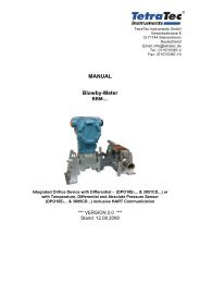
Control ValveModel <strong>8020</strong>-GS 1DN 15 - DN 150Pneumatic Control Valve for the control and switching of neutralthrough to highly aggressive media in process engineering,chemical industries and for plant equipment.• Space saving wafer type construction• Lowest possible weight• Quiet operation• Fast response time• Control of high differential pressures with small actuators• Greatly reduced energy consumption rates due to short strokes and lowactuating forces on the throttle element• High Kvs-(Cv)-valuesTechnical InformationBody designFlangeless, wafer-type constructionDimension to DIN-EN 558-1 series 20more versions see on data-<strong>sheet</strong> <strong>8020</strong>-GS3Nominal sizes DN 15 to DN 150Nominal pressure PN 40, DIN 2401also for flanges PN 10 to PN 25Media temperatureBody 1.0570: -10°C to +300°CBody 1.4571: -60°C to +350°CAmbient temperature-20°C to +80°CRangeability 40 : 1Leakage Disc pair Disc pair(% of Kvs) Carbon-stainless steel STN 2< 0,0001 < 0,001Kvs- values see <strong>Data</strong>-<strong>sheet</strong> 8001Options- bellow (stainless steel)- positioner• pneumatic• electro-pneumatic• electro-pneumatic forhazardous location use(EEX ib II C T5/T6)- limit switches- position feedback- manual handwheelActuator with 125 cm² or250 cm² diaphragm areaDiaphragmCoupling with stroke indicatorPTFE-packing (selfadjusting)Head sectionGuide sleeveStem, roller burnishedStainless steel bellows (opt.)Wafer-type body for PN 10-40Fixed valve plateSliding disc (both safety positionsobtainable by inverting the disc 180°)Coupling ring for disc<strong>TetraTec</strong> <strong>Instruments</strong> <strong>GmbH</strong> Tel.: 07157 / 5387- 0, Fax: 07157 / 5387- 10Gewerbestraße 8, D-71144 Steinenbronn www.tetratec.de info@tetratec.de
Control Valve <strong>8020</strong>-GS1Admissible Differential Pressure(For temperatures of up to 120°C)Disc pair: carbon - stainless steelDiaphragm area125 cm²Spring range 0.2 to 1.0 to 1.5 to 1.8 to 2.1 to 0.2 to 0.8 to 1.2 to 1.5 to 1.7 to(bar) 1.0 2.0 3.0 3.8 4.5 1.0 1.4 2.2 2.7 3.2Supply air (bar) 1,2 2,8 4,2 5,2 6,0 1,2 2,1 3,2 4,0 4,6DN250 cm²Admissible differential pressures in bar (see pressure diagram for GS-Valves)For temperatures of 120°C and above:obey application limits !15 20 40 40 40 40 37 40 40 40 4020 16 40 40 40 40 34 40 40 40 4025 10 40 40 40 40 23 40 40 40 4032 6 40 40 40 40 19 40 40 40 4040 4 40 40 40 40 11 40 40 40 4050 - 36 40 40 40 6,5 40 40 40 4065 - 29 40 40 40 5 40 40 40 4080 - 17 26 33 39 3 30 40 40 40100 - 10 16 20 24 1,8 18 25 25 25125 - 6,5 10 13 15 1,2 12 16 16 16150 - 5 7,5 9 11 0,7 8,5 13 16 16Springconfiguration D 2 3 4 5 D 2 3 4 5StandardDisc pair: STN 2Diaphragm area125 cm² 250 cm²Spring range 0.2 to 1.0 to 1.5 to 1.8 to 2.1 to 0.2 to 0.8 to 1.2 to 1.5 to 1.7 to(bar) 1.0 2.0 3.0 3.8 4.5 1.0 1.4 2.2 2.7 3.2Supply air (bar) 1,2 2,8 4,2 5,2 6,0 1,2 2,1 3,2 4,0 4,6DNAdmissible differential pressures in bar (see pressure diagram for GS-Valves)15 12 40 40 40 40 30 40 40 40 4020 8 40 40 40 40 20 40 40 40 4025 6 40 40 40 40 15 40 40 40 4032 3 38 40 40 40 12 40 40 40 4040 2 23 27 27 27 5,5 27 27 27 2750 - 13 20 25 30 3 23 35 40 4065 - 10 16 20 24 2 18 28 34 3880 - 6 9 11 14 1,3 10 16 19 22100 - 3,5 5,5 7 8,5 0,7 6,5 10 12 13125 - 2,5 3,5 4,5 5,5 0,5 4 6,5 8 9150 - 1,5 2,5 3,5 4 0,4 3 4,5 5,5 6,5Springconfiguration D 2 3 4 5 D 2 3 4 5The quoted pilot pressure must be available as a minimum value for use without a positioner. If a positioner is applied the pilot pressure isdetermined by the adjustment of the positioner. The standard adjustment value is 4 bar gauge. The spring configuration D enables the useof the control valve without positioner in line with a restricted control capacity. In this case the valve can be driven by a controller with a standardsignal of 0.2 to 1.0 bar.Applications limits for GS1-Valves made of stainless steelPN 40StandardSliding unit: carbon - stainless steel, coatedmax. admissible diff. pressures for GS1-valvesSliding unit: carbon - STN2max. admissible diff. pressures for GS1-valvesDN 100°C 150°C 200°C 250°C 300°C 350°C 100°C 150°C 200°C 250°C 300°C 350°C15 - 65 40 38 35 32 28 24 40 38 35 32 28 2480 40 38 35 32 28 24 36 34 33 26 22 19100 33 31 29 27 25 24 33 31 29 24 20 17125 23 21 20 19 18 17 22 21 20 16 13 11150 16 15 14 13 12 12 16 15 14 11 9,5 8,5
Control Valve <strong>8020</strong>-GS1MaterialsBody Carbon steel 1.0570 Stainless steel 1.4571Head section Carbon steel 1.0570 Stainless steel 1.4571Diaphragm housing Aluminium KTL coatedPacking PTFE (Carbon filled), spring 1.4310Actuating stem Stainless steel 1.4571, roller burnishedBellows Stainless steel 1.4571Fixed disc Stainless steel 1.4571, coated STN2-discSliding disc Special carbon material STN2-discCoupling ring Stainless steel 1.4571Ordering-Number System1 2 3 4 5 6 7 8 9 10 11 12 13 14 15 168 0 2 0 / V P M Z S 1 - 5 : Please quote all 5 sections.6 - 12: Quote only if required.Symbol: "V": ValveType Size"R": Repair kit (sealings)1. Type 2. Connection 3. Body 4. Safety 5. Actuator 6. Special 7. Springs 8. Stem sealingmaterial positionversionsP Pneumaticcontrol valve0 Flangelessdesign acc.0 Carbon steel1.05700 springcloses3 Diaphragm125 cm²M State, if furthersections are- Standard - PTFE-packing, selfadjusting (standard)DIN2632-2635 1 Stainless 1 spring 4 Diaphragm quoted 1 2 springs 1 Additional bellow(PN10-PN40) 1.4571 opens 250 cm² 2 4 springs 14.5713 6 springs4 8 springs5 10 springsD Spring set0,2-1 bar9. Moving disc 10. Fixed disc 11. Kvs-values 12. Characteristic13. Accessories- Carbon material - Stainless stell - 100% - linear Z Accessories1.4571, coated (Stand.)9 STN2-disc 1 STN2-disc A red. to 63% 1 equalpercentageB Carbon material,fibre-reinforced1 red. to 40% 2 p/p-positionerw ith gaugesB red. to 25% 3 i/p-positionerw ithout2 red. to 16% 4 i/p-positionerw ith gaugesC red. to 10% 6 i/p-positioner,3 red. to 6,3% ex-proof,4 red. to 2,5% w ithout5 red. to 1% 7 i/p-positioner,7 red. to 12% ex-proof,8 red. to 2% w ith gauges9 red. to 0,4 %14. Positioner 15. Feedback 16. Special versions- w ithout - Without S Further specialversions1 p/p-positioner 0 2 ind. limitw ithoutsw itches M12x1gaugesDC 10-30V5 2 ind. limitsw itches M12x1DC 10-55VD 1 ind. limit sw itchM12x1 DC 10-6 1 ind. limit sw itchM12x1 DC 10-Ordering Example:<strong>8020</strong>/080VP0103M5 - - - - - Z3GS-control valve with pneumatic actuator, DN 80, PN 10/40, stainless steel,normally closed,actuator 125 cm² (standard design) with 10 springs, PTFE-V-shaped seal, carbon material-stainlesssteel 1.4571, Kvs-value 100 %, Flow characteristic linear, I/p-positioner without gauges.
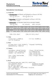
Control Valve <strong>8020</strong>-GS1Dimensions and WeightsDimensions and WeightsDN A C Ø DL Weight (Kg) Strokemm mm for actuator mm for actuator mm125 250 125 25015 53 305 165 222 33 5,9 8,1 620 62 310 165 222 33 6 8,2 625 72 315 165 222 33 6,2 8,4 632 82 320 165 222 33 6,5 8,7 640 92 325 165 222 33 6,7 8,9 650 108 335 165 222 43 7,9 10,1 865 127 345 165 222 46 8,7 10,9 880 142 355 165 222 46 9,3 11,5 8100 164 365 165 222 52 10,5 12,7 8,5125 194 380 165 222 56 12,7 14,9 8,5150 219 395 165 222 56 14,2 16,4 8,5Text and pictures are not binding. We reserve the right, to alter the equipment.with pneumatic positioner<strong>Data</strong> <strong>sheet</strong> <strong>8020</strong>e/Version: 12.01.2006with electropneumatic positioner