
Create successful ePaper yourself
Turn your PDF publications into a flip-book with our unique Google optimized e-Paper software.
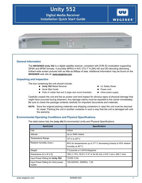
<strong>Unity</strong> <strong>552</strong><br />
Digital Media Receiver<br />
Installation Quick Start Guide<br />
.<br />
General Information<br />
The WEGENER <strong>Unity</strong> <strong>552</strong> is a digital satellite receiver, compliant with DVB S2 modulation supporting<br />
QPSK and 8PSK formats. It provides MPEG-4 AVC (ITU-T H.264) HD and SD decoding delivering<br />
brilliant wide screen pictures with as little as 6Mbps of data. Additional information may be found on the<br />
WEGENER web site at: www.wegener.com.<br />
Unpacking and Inspection<br />
The box containing the unit should include:<br />
• <strong>Unity</strong> <strong>552</strong> Media Receiver • UL Safety Sheet<br />
• Quick Start Guide • Power cord<br />
• Parts (4 rubber feet and 2 angle rack mount brackets) • Inline power supply<br />
Carefully unpack the unit and the ac power cord and inspect for obvious signs of physical damage that<br />
might have occurred during shipment. Any damage claims must be reported to the carrier immediately.<br />
Be sure to check the package contents carefully for important documents and materials.<br />
NOTE:<br />
Save the original packing materials and shipping containers in case the unit must be returned<br />
for repair. Packing the unit in another container in such a way that the unit is damaged will void<br />
the warranty.<br />
Environmental Operating Conditions and Physical Specifications<br />
The table below lists the <strong>Unity</strong> <strong>552</strong> Environmental Limits and Physical Specifications<br />
Item/Limit<br />
Specification<br />
Use<br />
Altitude<br />
Temperature Range<br />
Relative Humidity (max.)<br />
Weight<br />
Dimensions (H x W x D)<br />
Indoor<br />
Up to 3048 meters<br />
10 o C to 40 o C<br />
Input Power Rating for <strong>Unity</strong> <strong>552</strong> 12VDC 5.0A<br />
Input Power Rating for inline power<br />
supply<br />
80% for temperatures up to 31 o C decreasing linearly to 50% relative<br />
humidity at 40 o C<br />
7.5 pounds or 3.4019 kilograms<br />
1RU (1.75"x 16.5"x 11.5" or 44.45 mm x 419.1 mm x 292.1 mm)<br />
100-240VAC, 50/60Hz, 1.5A<br />
www.wegener.com 800089-02D 1
QUICK START GUIDE<br />
Location and Mounting<br />
The <strong>Unity</strong> <strong>552</strong> may be mounted in a standard 19-inch equipment rack or set up for desktop operation. In<br />
either location, maintain a clean, dry environment for the <strong>Unity</strong> <strong>552</strong>.<br />
Rack Mounting<br />
The <strong>Unity</strong> <strong>552</strong> unit should be installed in such a way that a half-inch clearance is allowed on each side<br />
and a quarter-inch on the top to ensure adequate air flow. Ensure that a hazardous condition is not<br />
produced by uneven loading, or by resting any unsupported equipment on a rack-mounted <strong>Unity</strong> <strong>552</strong><br />
unit.<br />
Parts for the <strong>Unity</strong> <strong>552</strong> unit include 2 angle rack mount brackets and 4 rubber feet. For rack mounting,<br />
install the angle rack mount brackets as following; however do not attach the rubber feet as they<br />
interfere with the rack mounting.<br />
1. Remove the 2 screws from the left and right sides of the unit.<br />
2. Insert the angle brackets into the left and right sides of the unit ensuring that the screw holes for<br />
the unit and brackets are aligned.<br />
3. Secure the brackets by re-inserting the screws through the brackets and unit.<br />
4. Install the unit onto the rack.<br />
NOTE:<br />
The front brackets must be secured to the rack. If the front brackets are left unsecured, the unit<br />
may shift forward and fall from the rack, and may result in personal injury and/or damage to the<br />
equipment. The internal temperature of the rack should not exceed 40 o C.<br />
Desktop Installation<br />
Parts for the <strong>Unity</strong> <strong>552</strong> unit include 2 angle rack mount brackets and 4 rubber feet. For desktop<br />
installation, attach the 4 rubber feet; however do not attach the rack mount brackets.<br />
1. Attach the 4 rubber feet onto the indented areas at the bottom of the unit.<br />
2. Place the unit on a flat surface where it will not be subject to spills or impacts.<br />
3. Route cables to the unit so that they will not be hit or pulled, causing damage to the connectors<br />
or to the unit itself. Ensure a sufficient flow of cool air so that the unit's operating ambient<br />
temperature range is not exceeded.<br />
WARNING: FCC-Mandated Suppression of Radio Frequency Emissions<br />
This is a Class A product. In a domestic environment this product may cause radio<br />
interference for which the user may need to take mitigating action.<br />
If the Ethernet port has a cable connected to it, that cable must be properly shielded<br />
and grounded to minimize RF emissions that could interfere with nearby equipment.<br />
Circuit Protection and Earthing<br />
When connecting the <strong>Unity</strong> <strong>552</strong> unit to the power supply, review the ratings of all equipment in the<br />
circuit to ensure that the branch circuit, as well as the power source, will not be overloaded. Also make<br />
sure that the unit is properly grounded and/or that a protected power strip is used to attach it to the<br />
power supply.<br />
2 800089-02D www.wegener.com
1.000 .000 [25.40] [.00]<br />
.001 1.000 [0.03] [25.40]<br />
DIM STANDARDS<br />
.000 NON-ASSOCITIVE<br />
DECIMAL-METRIC_ALT<br />
STANDARD<br />
STANDARD<br />
0.0010 [.00]<br />
1.000 DECIMAL-METRIC_ALT_LIB<br />
NON-ASSOCITIVE<br />
1.000<br />
[25.40]<br />
[25.40]<br />
DECIMAL-METRIC_ALT-LIB<br />
1.000 NON-ASSOCITIVE<br />
DECIMAL-METRIC_ALT<br />
.001<br />
ASSOCITIVE<br />
1 [0.03]<br />
0 FRACTION-METRIC_ALT<br />
FRACTION-METRIC_ALT<br />
[0.03]<br />
[25.40]<br />
PLOT Acrobat<br />
STANDARDS<br />
PDF Writer A-SIZE B-SIZE<br />
HP 1220C 6310 A-SIZE B-SIZE A-SIZE B-SIZE<br />
JPEG Hi-Res<br />
XANTE 1600<br />
8200 A-SIZE<br />
x 1200<br />
B-SIZE<br />
QUICK START GUIDE<br />
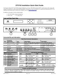
Rear Panel Connections<br />
Figure 1 shows the rear panel connections of the <strong>Unity</strong> <strong>552</strong> that are described in Table 3.<br />
Figure 1: <strong>Unity</strong> <strong>552</strong> rear panel view with HDMI port<br />
DC IN<br />
12 V 5 A<br />
S/N<br />
000000<br />
RF IN<br />
RS232<br />
Ma nufa ctured under lic ens e from<br />
Dolby La bora tories .<br />
"Dolby " and the double- D symbol<br />
are trademarks of Dolby Laboratories.<br />
GPIO<br />
AUDIO 1<br />
Pr Pb Y<br />
COMPONENT<br />
VIDEO<br />
ETHERNET<br />
1<br />
2<br />
3<br />
4<br />
1<br />
6<br />
R<br />
L<br />
AUDIO 2<br />
0.1A @ 30VDC<br />
COMPOSITE<br />
VIDEO<br />
MO N<br />
HDMI<br />
R<br />
L<br />
C-VIDEO<br />
S/PDIF<br />
S/PDIF<br />
US B<br />
RS232 Pinout Connections<br />
Table 1 shows the pinout connections for the Serial Port RS-232 Phone Jack.<br />
Pinout Connections<br />
Table 1: Serial Port RS-232 Pinouts<br />
Pin Input Output Description Pin Input Output Description<br />
1 No Connection 4 No Connection<br />
2 Output RXDB Data 5 Ground<br />
3 Input TXDB Data 6 +5V DC<br />
Table 2 shows the pinout connections for the DB-9 Female GPIO.<br />
Interconnect Descriptions<br />
Table 2: DB-9 Female GPIO Pinouts<br />
Pin Input Output Description Pin Input Output Description<br />
1 Alarm Common 6 Alarm Normally Closed<br />
2 Alarm Normally Open 7 Contact Closure Normally Closed<br />
3 Contact Closure Common 8 Contact Closure Normally Open<br />
4 No Connection 9 Ground<br />
5 Contact Closure GPIO Input<br />
(Factory Use Only)<br />
Table 3 shows the rear panel connections of the <strong>Unity</strong> <strong>552</strong>.<br />
Table 3: <strong>Unity</strong> <strong>552</strong> Interconnect Descriptions<br />
Signal Connector Description<br />
DC IN Male Power Jack +12 VDC @ 5A<br />
RF Switch IN - Port 1 F 950 to 2150 MHz signal accepted. LNB power available<br />
RF Switch IN - Port 2, 3, 4 F 950 to 2150 MHz signal accepted. NO LNB power available<br />
RS232 Port RJ-12 Serial Asynchronous Data. May be used for terminal, printer, or<br />
auxiliary data<br />
Audio OUT 2 (R & L) 2 RCA Phono Jacks Audio stereo<br />
GPIO D-Type Two Relays 01.A @ 30 V DC (GPIO for Factory Use Only)<br />
www.wegener.com 800089-02D 3
QUICK START GUIDE<br />
Signal Connector Description<br />
Composite Video RCA Phono Jack Composite Video Monitor NTSC or PAL at 1 Vp-p<br />
C-Video RCA Phono Jack C-Video NTSC or PAL, Composite video at 1 Vp-p<br />
Component Video 3 RCA Phono Jacks Component SD/HD Video YPbPr<br />
Audio OUT 1 (R&L) 2 RCA Phono Jacks Audio Stereo<br />
HDMI Type A receptacle High Definition Multimedia Interface (Digital A/V)<br />
S/PDIF RCA Phono Jack S/PDIF Coax Digital Audio<br />
S/PDIF Optical TosLink S/PDIF Fiber Digital Audio<br />
ETHERNET RJ-45 ETHERNET 10/100 BaseT<br />
USB USB USB<br />
CAUTION: Do not connect RJ-12 directly to phone line. Equipment damage may result.<br />
Front Panel Connections<br />
Figure 2 show the <strong>Unity</strong> <strong>552</strong> front panel controls and describes them in Table 4. The IRD can be<br />
controlled via Compel Network Control, local terminal, and On-Screen-Display push buttons. Normally,<br />
Compel is the primary method of controlling the IRD, while the other control methods are supplemental.<br />
Figure 2: <strong>Unity</strong> <strong>552</strong> Front Panel<br />
left arrow button<br />
right arrow button<br />
top arrow button<br />
LED<br />
LCD screen<br />
bottom arrow button<br />
Enter button<br />
Table 4: <strong>Unity</strong> <strong>552</strong> Front Panel Controls<br />
Item<br />
LCD<br />
Arrow buttons<br />
ENTER<br />
Description<br />
Activates automatically by certain status conditions, such as loss of signal.<br />
To manually activate, press the ENTER button.<br />
Push buttons activates LCD and selects options displayed.<br />
Push button enters options selected on LCD.<br />
LCD Menu Navigation<br />
Operate the <strong>Unity</strong> <strong>552</strong> from the front panel using the arrow buttons and the LCD as shown in Figure 2.<br />
Menu screens on the LCD direct you to screens that control various operating functions including:<br />
• programming<br />
• audio<br />
4 800089-02D www.wegener.com
QUICK START GUIDE<br />
Front Panel Functions<br />
Programming Setup<br />
1. Use the right or left arrow buttons to navigate to Prgm:Prog1.<br />
2. To edit, press Enter.<br />
3. To navigate to Prog2 or Prog3, use the top and bottom arrow buttons.<br />
4. To change, press Enter.<br />
Audio Setup<br />
Use to setup Audio 1 or Audio 2 as indicated on the rear of the unit chassis.<br />
1. Use the right or left arrow buttons to navigate to Aud:A01 or Aud:A02<br />
2. To edit, press Enter.<br />
3. To change, press Enter.<br />
Closed Captioning (CC) Setup<br />
1. Use the right or left arrow buttons to navigate to Sub:CC1.<br />
2. To edit, press Enter.<br />
3. To navigate to Sub:CC2 or Sub:CC3 or Sub:CC4, use the top and bottom arrow buttons.<br />
4. To change, press Enter.<br />
LED Indications after Power-Up<br />
Upon power up, the IRD initializes all system components and supplies an operational status. A steady<br />
Green LED indicates that it is locked on a carrier and is capable of producing output (Audio/Video/<br />
Data).<br />
If there is some problem with the IRD or the signal it is receiving the LED flashes Red for alarm<br />
conditions or Amber for warning conditions. In general, alarms indicate that the unit cannot produce<br />
output, while Warnings indicate that, although output is being produced, there is a problem that could<br />
require attention. The most common conditions that produce alarms or warnings are listed in Table 5.<br />
Table 5: <strong>Unity</strong> <strong>552</strong> Front Panel Status LED Alarm and Warning Indications<br />
Mode LED Status Condition<br />
Alarm<br />
Warning<br />
Red blink = 2<br />
Red blink = 3<br />
Red blink = 4<br />
Red blink = 5<br />
Red blink = 11<br />
Amber blink = 1<br />
Amber blink = 2<br />
Amber blink = 4<br />
Amber blink = 5<br />
Amber blink = 6<br />
Amber blink = 7<br />
No carrier<br />
No RF signal<br />
In recovery<br />
Eb/No alarm<br />
Not authorized<br />
No response from SEC_MICRO<br />
Marginal Eb/No<br />
Selected audio not available<br />
RF too low<br />
RF too high<br />
Application download failed<br />
Normal Green Normal operation<br />
www.wegener.com 800089-02D 5
QUICK START GUIDE<br />
OSD (On-Screen Display)<br />
Although the <strong>Unity</strong> <strong>552</strong> is set up at the factory, you can customize its settings to fit your system using<br />
the OSD and front-panel buttons. With a monitor attached to the <strong>Unity</strong> <strong>552</strong> through any of the video<br />
output ports of the IRD, you may use the push buttons to navigate through the menus displayed to view<br />
the existing settings, various status, and version fields.<br />
Some of the functions you can perform using the OSD menus are:<br />
• Tune to a Carrier<br />
• Configure LNB<br />
• Monitor Signal Quality<br />
• Set Audio/Video Decoder Options<br />
• Set Subtitling<br />
• Set Relays<br />
• Set Networking options<br />
• View Version Information<br />
OSD Setup<br />
The OSD information displays white text on a blue background overlying 80% of the video output from<br />
the <strong>Unity</strong> <strong>552</strong> receiver. View the OSD from a monitor connected to any of the video output ports of the<br />
<strong>Unity</strong> <strong>552</strong> receiver.<br />
NOTE:<br />
From the front panel, press any key to activate the OSD.<br />
OSD Menus<br />
All menus are white text with a blue background. Highlighted items display as black text on a white<br />
background. Figure 3 is a representation of the OSD Main Menu.<br />
Figure 3: OSD Main Menu<br />
Navigating OSD Menus<br />
Use the arrow and Enter buttons on the <strong>Unity</strong> <strong>552</strong>’s front panel to navigate and edit the fields on the<br />
OSD menus. Selectable fields allow you to change the whole parameter from pre-determined options.<br />
Editable fields allow you to change each digit of the parameter.<br />
NOTE:<br />
Once a field is updated, you must select Activate and Exit on the submenu and then press<br />
Enter to update the value of the field. Before pressing Enter, you may go back to any field and<br />
correct it prior to acceptance.<br />
6 800089-02D www.wegener.com
QUICK START GUIDE<br />
Table 6: <strong>Unity</strong> <strong>552</strong> Types of OSD Action Fields<br />
Button<br />
Actions<br />
Main Menu Submenu Edit Mode<br />
Enter<br />
Decoder Setup<br />
selects submenu or<br />
dropdown list<br />
goes to editable field<br />
The Decoder Setup menu is available from the OSD Advanced Setup in the Main Menu, followed by<br />
Unit Setup. See Figure 4: OSD Decoder Setup Menu below.<br />
Figure 4: OSD Decoder Setup Menu<br />
accepts changes<br />
right arrow no action no action moves cursor to right<br />
left arrow exits OSD goes to previous menu level moves cursor to left or<br />
abandon changes<br />
up arrow<br />
down arrow<br />
goes to next or previous<br />
menu item<br />
goes to next or previous<br />
menu item<br />
goes to next or previous menu<br />
item<br />
goes to next or previous menu<br />
item<br />
increases value of<br />
highlighted item<br />
decreases value of<br />
highlighted item<br />
The following options for decoding the output are available:<br />
Decoder Source<br />
Controls source of input for the primary A/V decoder. The Follow Tune indicates that currently transport<br />
stream is playing from the selected RF source and program number. The source can be changed to<br />
Multicast UDP from Satellite/RF or Multi/Unicast UDP from LAN/ETHERNET port. The source can be<br />
turned off to produce no video/audio output.<br />
TV Aspect Ratio<br />
Allows the receiver to automatically correct a mismatch in the aspect ratio of TV to the content being<br />
displayed. Available values are 4x3 (Traditional TV), 16x9 (Widescreen TV) and 14x9 (CiniView II).<br />
www.wegener.com 800089-02D 7
QUICK START GUIDE<br />
Warranty<br />
Output Scaling<br />
Controls the behavior aspect ratio if the content does not match the TV Aspect Ratio. In Letterbox<br />
mode, black bars are displayed either at the top/bottom or at the sides for better viewing quality. The<br />
Pan/Scan mode is also available. Improvement in viewing experience depends on the source contents.<br />
Closed Captioning<br />
PASSTHRU Mode allows the TV to display subtitling information according to NTSC/PAL standards.<br />
Alternatively, the receiver can render subtitling information if the mode is set to either CC1:4 (EIA-608),<br />
DTV (EIA-708-B), or Divicom.<br />
Composite Out<br />
Selects video output format either for NTSC_M, NTSC_J, PAL/50 or PAL/60.<br />
Component Out<br />
Selects video output format either for 480i/p, 576i/p, 720p or 1080i. When a DVI/HDMI device is<br />
connected, the mode shall be automatically set to Slave.<br />
Component VRefresh<br />
Configures the video/vertical refresh rate either to 50, 60 or 59.94 frames per second.<br />
HDMI Out<br />
Displays current display mode of the DVI/HDMI device after negotiation.<br />
The following warranty applies to all WEGENER products:<br />
All WEGENER products are warranted against defective materials and workmanship for a period of one<br />
year after shipment to customer. <strong>Wegener</strong> Communications' obligation under this warranty is limited to<br />
repairing or, at <strong>Wegener</strong> Communications' option, replacing parts, subassemblies, or entire assemblies.<br />
<strong>Wegener</strong> Communications shall not be liable for any special, indirect, or consequential damages. This<br />
warranty does not cover parts or equipment, which have been subject to misuse, negligence, or accident<br />
by the customer during use. All shipping costs for warranty repairs shall be prepaid by the customer.<br />
There are no other warranties, express or implied, except as stated herein.<br />
Technical Support<br />
In the event that the unit fails to perform as described, contact <strong>Wegener</strong> Communications Customer<br />
Service at:<br />
• Phone: (770) 814-4057<br />
• Fax: (678) 624-0294<br />
• E-mail: service@wegener.com<br />
Corporate Office:<br />
WEGENER<br />
Service Department:<br />
WEGENER<br />
11350 Technology Circle Customer Service<br />
John's Creek<br />
359 Curie Drive<br />
Duluth, GA 30097 Alpharetta, GA 30005<br />
8 800089-02D www.wegener.com