200- 450 MHz QUADRATURE HYBRID USING LANGE COUPLER ...
200- 450 MHz QUADRATURE HYBRID USING LANGE COUPLER ...
200- 450 MHz QUADRATURE HYBRID USING LANGE COUPLER ...

Create successful ePaper yourself
Turn your PDF publications into a flip-book with our unique Google optimized e-Paper software.
A Project Report on<br />
<strong>200</strong>- <strong>450</strong> <strong>MHz</strong> <strong>QUADRATURE</strong> <strong>HYBRID</strong> <strong>USING</strong><br />
<strong>LANGE</strong> <strong>COUPLER</strong><br />
By<br />
Ajay C.Lakade (Roll No:990328)<br />
Hemant D.Chaudhari (Roll No:<strong>200</strong>00313)<br />
Ratnakar A. Ghodeswar (Roll No:<strong>200</strong>10314)<br />
Under The Guidance of<br />
Mr. A. Praveen Kumar<br />
Department of Electronics and Telecommunication<br />
Engineering,<br />
Dr. Babasaheb Ambedkar Technological University,<br />
Lonere<br />
Tal-Mangaon Dist-Raigad 402 103<br />
(<strong>200</strong>5-<strong>200</strong>6)
ACKNOWLEDGEMENT<br />
We would like to avail this opportunity to express our heart felt<br />
gratitude towards our guide Mr. A. Praveen Kumar, GMRT,TIFR for his<br />
constant guidance and encouragement.<br />
We are also very thankful to Mr. S. Sureshkumar, GMRT, TIFR for<br />
his timely assistance and advice without whom we would not be able to<br />
complete our project.<br />
We also express our gratitude to Mr.Vinod Pacharane who helped<br />
us in fabricating the PCB'S. We are also thankful to Mr.Sandeep<br />
Chaudhari for helping us in our project We also would like to thank staff<br />
of GMRT for giving us the support and help during our project.<br />
We also express our gratitude towards Mr.Sanjay Dongare for<br />
helping us during the documentation stage.<br />
Date: 20 th march <strong>200</strong>6 Ajay C.Lakade<br />
Hemant D.Chaudhari<br />
Ratnakar A. Ghodeswar
Introduction<br />
“Lange coupler” is an interdigited microstrip quadrature hybrid coupler as<br />
described by Dr. Julius Lange in 1969 [1]. The main advantages are the small<br />
size and its relatively large bandwidth, when compared with Branch-Line<br />
Coupler. Branch-Line Couplers offer bandwidth of about 20% and they require<br />
large substrate area. The other alternative approach to design the quadrature<br />
hybrid is the use of Sage Laboratories make “WIRELINE”. “WIRELINE” is<br />
available in two types, one for 30% bandwidth and the other for octave<br />
bandwidth. WIRELINE is more lossy as compared with Lange coupler. Lange<br />
coupler can give upto 3:1 bandwidth and if realized on low dissipation factor<br />
substrates it can yield low insertion loss.<br />
Giant Meterwave Radio Telescope (GMRT) is being upgraded to have a<br />
frequency band of <strong>200</strong>-<strong>450</strong> <strong>MHz</strong>. This requires low loss polarizers covering this<br />
frequency range to convert linearly polarized signals from the upgraded feed to<br />
right and left circularly polarized signals. This report highlights the design<br />
aspects of a low loss <strong>200</strong>- <strong>450</strong> <strong>MHz</strong> Quadrature Hybrid based on Lange coupler<br />
approach for possible use in GMRT.
HISTORY OF <strong>LANGE</strong> <strong>COUPLER</strong><br />
Lange couplers are a modern miracle of microwaves. Here is the<br />
quadrature coupler at its best: low loss, wide bandwidth, compact layout. This<br />
coupler spawned an entire industry of wide band hybrid-style amplifiers that is<br />
still here today inspite of a lot of good competition from MMIC'S.<br />
"In 1969 at Texas Instruments, Julius Lange and others were building<br />
microwave amplifiers on thin film ceramic substrates. They were using the<br />
scheme invented by Engelbrecht at Bell Labs, which required 3-dB quadrature<br />
couplers. The challenge was to get tight coupling on single layer microstrip. On<br />
the other hand transistors had too much coupling between the interdigitated<br />
base and emitter fingers. Lange built an interdigitated coupler and it did not<br />
work well. Then he remembered that geometric symmetry guarantees<br />
quadrature, a 90° split between the outputs. So he moved some of the<br />
crossovers from the ends to the middle; and it worked! . So they could get a<br />
microstrip interdigitated quadrature coupler with low loss and wide, one octave,<br />
bandwidth."
Introduction<br />
“Lange coupler” is an interdigited microstrip quadrature hybrid coupler as<br />
described by Dr. Julius Lange in 1969 [1]. The main advantages are the small<br />
size and its relatively large bandwidth, when compared with Branch-Line<br />
Coupler. Branch-Line Couplers offer bandwidth of about 20% and they require<br />
large substrate area. The other alternative approach to design the quadrature<br />
hybrid is the use of Sage Laboratories make “WIRELINE”. “WIRELINE” is<br />
available in two types, one for 30% bandwidth and the other for octave<br />
bandwidth. WIRELINE is more lossy as compared with Lange coupler. Lange<br />
coupler can give upto 3:1 bandwidth and if realized on low dissipation factor<br />
substrates it can yield low insertion loss.<br />
Giant Meterwave Radio Telescope (GMRT) is being upgraded to have a<br />
frequency band of <strong>200</strong>-<strong>450</strong> <strong>MHz</strong>. This requires low loss polarizers covering this<br />
frequency range to convert linearly polarized signals from the upgraded feed to<br />
right and left circularly polarized signals. This report highlights the design<br />
aspects of a low loss <strong>200</strong>- <strong>450</strong> <strong>MHz</strong> Quadrature Hybrid based on Lange coupler<br />
approach for possible use in GMRT.
Theory of Lange coupler<br />
The Lange coupler is often used in hybrid and monolithic microwave<br />
integrated circuit applications. To balance voltages of alternate lines, bond<br />
wires have to be used.<br />
The physical length of a Lange coupler is approximately equal to one<br />
quarter wavelength at the center frequency on the host substrate. The<br />
combined width of the strips is comparable to the width of a line of<br />
characteristics impedance Z 0<br />
(50 ohm) on the host substrate.<br />
Lange couplers are a common circuit used in microwave applications.<br />
They provide equal power division and 90 degrees of phase shift between<br />
the coupled ports. They are widely used as power combiners and splitters<br />
in microwave amplifiers and in mixers/modulators. They are based upon<br />
interdigitated lines with narrow lines and tight spaces.<br />
The coupling in coupled lines coupler is too loose to achieve coupling<br />
factors of 3 db or 6db. One way to increase coupling between edge coupled<br />
lines is to use several lines parallel to each other, so that fringing fields at<br />
both edges of a line contribute to the coupling. Lange coupler can easily<br />
achieve 3 db coupling ratios, with an octave or more bandwidth. The<br />
design tends to compensate for unequal even and odd phase velocities,<br />
which also improves the bandwidth.<br />
There is 90 degrees phase difference between output lines(port 2 and<br />
3), so the Lange coupler is also called quadrature coupler. The main<br />
disadvantage of Lange coupler is, as the lines are very narrow, closed<br />
together, it is difficult to fabricate the necessary bonding wires across the<br />
lines.
For a given input on a Lange coupler (or other types of quadrature<br />
couplers for that matter), the three output ports can be denoted<br />
1] isolated port<br />
2]through or direct port<br />
3]coupled port (-90 degree transmission angle compared to through port)<br />
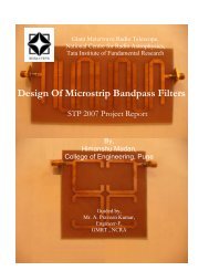
Referring to the six finger Lange coupler below, if the bottom left port is<br />
the input, the top left is the "coupled" port, the top right is the "direct" port and<br />
the bottom right is the "isolated" port. The isolated port is on the same side of<br />
the coupler as the input for a normal Lange coupler.<br />
The network in figure b still belongs to the Lange Coupler family shown in<br />
part a of the figure. It was first suggested by R.Waugh and D. Lacombe(2).It is<br />
usually called an “Unfolded Lange Coupler”,and the difference between these<br />
two networks is that they exchange the isolated and direct port as we see in<br />
figure a & b. For both the versions each of the coupled lines is called a “Finger”<br />
in the normal practice.<br />
Figure 1: Lange coupler
We see that a number “n” of coupled lines with length λ/4 are connected<br />
together at each extreme. In the case of part a of the figure the two λ/8 lines<br />
form λ/4 line for those frequencies where the length of connecting wires may be<br />
neglected. The number “n” of coupled lines is usually an even number, typically<br />
4 or 6 although in theory it is possible to use 3 lines. The Lange coupler is also<br />
called an “interdigital coupler” or simply “hybrid”. The connections are indicated<br />
in figure with solid thick lines and are called “ air bridges”. With the hypothesis<br />
of neglecting the length of the air bridges the Lange Coupler may be thought of<br />
as many Quarter wavelength directional couplers connected in parallel.<br />
With reference to figure, a signal entering in port 1 has the coupled port<br />
2 and the direct port 4, while port 3 is isolated. In addition, phase shift between<br />
signals at direct and coupled ports is 90 degrees. For this reason, the Lange<br />
coupler is also called a “3db quadrature hybrid”.<br />
Due to this multicoupling effect between the fingers, with the Lange<br />
coupler it is possible to reach 3db of coupling or even more with the<br />
consequences that this network is the only “3db Quadrature microstrip coupler”<br />
employed in practice in wide bandwidth circuits. For 4 fingers network and<br />
2.5db of center band coupling, it is possible to reach operating bandwidth of<br />
100%, that is 3:1 between the limits of frequency band. Therotically, coupling<br />
increases with the number of fingers, but in practice only 4 fingers are used.<br />
The therotical increase of coupling is limited by the increase in the number of<br />
discontinuities encountered using a higher number of fingers.<br />
One of the simplest studies on the Lange coupler was made by Wen Pin<br />
Ou [3]. His paper attempts to give a theoretical treatment of the interdigitated<br />
structure. In this method the equivalence of the coupler is used with an array<br />
of coupled transmission lines. The air bridges that connect the coupled lines in<br />
parallel must be evaluated with zero length in such a case all the lines<br />
connected in parallel are equipotential at the connection points in particular the<br />
two λ/8 lines are connected in series with a zero length connection. R.M.Osmani
[4] showed that it is possible to synthesize Lange Couplers directly and there by<br />
saving considerable computing time. In this direct synthesis procedure Wen Pin<br />
Ou's method is first used to determine odd and even-mode impedances of any<br />
adjacent pair of lines. Final dimensions are obtained by applying the synthesis<br />
technique of Akhtarzad et al[5] for a pair of coupled microstrip lines. This<br />
synthesis technique was found to be fairly accurate and quite simple to use. The<br />
procedure described above assumed coupled lines of zero conductor thickness.<br />
Neglecting finite conductor thickness in design is known to result in couplers<br />
with over coupled responses to counter this, Presser[6] suggested an empirical<br />
technique which increase zero thickness design spacing and reduces zero<br />
thickness design width by an equal amount determined from Wheeler's[7] edge<br />
correction for single strips of small thickness. For the coupler fabricated above<br />
over coupling caused by assuming T=0 was estimated by using Presser's<br />
method. Since the nominal T/d ratio of the substrate used is 0.07(1 oz/Sq.Ft<br />
copper). The equation given by Presser[6] cannot be applied straight away.<br />
Instead,Wheeler's edge correction for single strips of moderately large<br />
thicknesses is applicable[8].
Lange Coupler Design<br />
Lange couplers consist of very narrow coupled lines of a quarter<br />
wavelength coupled in parallel to allow fringing on both sides of the line to<br />
contribute to the coupling. To increase the coupling it is necessary to use very<br />
narrow gaps and to still further increase the coupling bond wire<br />
interconnections are used. The resultant coupler will have a large bandwidth of<br />
at least an octave and so for our application we will have plenty of bandwidth<br />
(Lange bandwidth ~ <strong>200</strong><strong>MHz</strong> to <strong>450</strong><strong>MHz</strong>).<br />
Figure 2
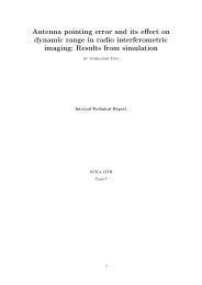
To calculate the finger dimensions and spacings, we need to calculate<br />
the even and odd mode line impedences:<br />
Figure:3
Design Formulas:<br />
1) λair = c/f<br />
where,<br />
c = speed of light in air (3E8 m/s)<br />
f = desired center frequency<br />
2) λ/4(in microstrip) = λair/4*√ εe<br />
where,<br />
λ/4(in microstrip) = length of Lange coupled lines<br />
εe = effective dielectric constant<br />
3) Port width for a 50 ohms line:<br />
4) Effective dielectric constant
Specifications of RT/duroid 5870 substrate<br />
For realizing the Lange coupler low loss substrate RT/duroid 5870 glass<br />
microfibre reinforced polytetra fluoroethylene(PTFE) composite manufactured by<br />
ROGERS corporation,USA has to be used. The specifications for this substrate<br />
are as under<br />
1. Dielectric constant (εr) =2.33<br />
2. Substrate height (d) = 1.6mm<br />
3. Metal Thickness = 35µm<br />
4. Loss Tangent (tan δ)= 0.0012<br />
5. 1 ounce/ sq.ft electrodeposited copper clad on both sides
Design of Lange coupler for <strong>200</strong>- <strong>450</strong><strong>MHz</strong> at a center<br />
frequency of 325<strong>MHz</strong> using RT/duroid 5870<br />
Substrate(εr =2.33)<br />
From graph as shown above we get,<br />
s/d= 0.1 & w/d= 0.07<br />
where d= height of substrate=0.06inch = 1.6mm<br />
s = spacing between coupled lines<br />
= 0.1* 1.6= 0.16mm<br />
w = width of coupled lines<br />
= 0.07* 1.6<br />
= 0.112mm<br />
εeff = (2.33+1)/2<br />
= 1.7156<br />
+ (2.33-1)/2 * 1/√ (1+12(d/w))<br />
λair = 3e8/325<strong>MHz</strong><br />
= 0.923 metre<br />
λ/4(in microstrip) = 0.923/4√ 1.71<br />
= 176.170mm
This is the final design for a Lange coupler showing all the<br />
dimensions:<br />
Figure 4: Final Design (Layout)
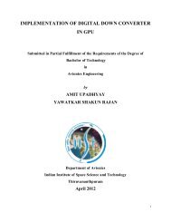
Figure 5: Ideal Response of Lange Coupler
An ideal responses for a particular design centered at 7.5 GHz<br />
frequency simulated by using ADS Agilent Software<br />
Figure 6: Amplitude & Phase Response of Lange Coupler
Design Realization<br />
The Lange Coupler was designed using the above mentioned procedures.<br />
The design was then simulated using the RF Design CAD Software GENESYS V8<br />
of Eagleware Corporation,USA .The summary of the simulated results are as<br />
under:<br />
Average Insertion Loss<br />
:0.15 dB<br />
Signal Division (<strong>200</strong>-<strong>450</strong><strong>MHz</strong>) :3 +/- 2 dB<br />
Phase Response (<strong>200</strong>-<strong>450</strong><strong>MHz</strong>) :90 (+ 4)/(- 0.5) degrees<br />
Input Return Loss (<strong>200</strong>-<strong>450</strong><strong>MHz</strong>): 25 dB(min.)<br />
Isolation (<strong>200</strong>-<strong>450</strong><strong>MHz</strong>) :37 dB(min.)<br />
The simulated response are shown in the figures:
Limitations of Lange Coupler:<br />
Although Lange coupler is the most used wideband microstrip<br />
Quadrature Hybrid , its physical realization always requires quite a small line<br />
width 'w' and coupling spacing 's'. Therefore fabrication of Lange Coupler<br />
requires high precision PCB manufacturing facility.<br />
Applications of Lange Couplers<br />
1)Attenuators<br />
2)Balanced Amplifiers<br />
3)Balanced Mixers<br />
4)Discriminators<br />
5)Phase Shifters<br />
6)Modulators<br />
7)90 Degrees Power Splitter<br />
8)Polarizers
References:<br />
[1] J. Lange, “Interdigitated stripline Quadrature<br />
Hybrid”,IEEE Transactions on Microwave Theory and<br />
Techniques, Vol. MTT-20, December 1969,<br />
Pages:1150-1151<br />
[2] R.Waugh and D. Lacombe, “Unfolding the Lange Coupler”, IEEE<br />
Transactions on Microwave Theory and Techniques, Nov 1972<br />
Pages:777<br />
[3] Wen Pin Ou, “Design Equations for an Interdigitated Directional<br />
Coupler”, IEEE Transactions on Microwave Theory and<br />
Techniques, Pages:253-255.<br />
[4] R.M.Osmani, “ Synthesis of Lange Couplers”,IEEE<br />
Transactions on Microwave Theory and Techniques, Vol. MTT-29,<br />
No.2 1972, Pages:168-170.<br />
[5] Sina Aktharzad, Thomas R. Rowbotham and Peter B. Johns, “The<br />
Design of Coupled Microstrip Lines”,IEEE Transactions on<br />
Microwave Theory and Techniques,Vol MTT-23 No.6,<br />
June1975,Pages:486-492<br />
[6] Presser A, “ Interdigitated Microstrip Coupler Design”,IEEE<br />
Transactions on Microwave Theory and Techniques,vol. MTT- 26,<br />
October 1978, Pages:801-805.<br />
[7] H.A.Wheeler, “ Transmission Line Properties of Parallel Strips<br />
Separated By a Dielectric Sheet”,IEEE Transactions on Microwave<br />
Theory and Techniques,Vol. MTT-13,March 1965,Pages:172-185<br />
[8] H.A.Wheeler, “ Transmission Line Properties of a Strip on a<br />
Dielectric Sheet on a Plane “,IEEE Transactions on<br />
Microwave Theory and Techniques,Vol. MTT-25,August<br />
1977,Pages:631-647<br />
[9] Krzysztof Sachse, Andrzej Sawicki, Grzegorz Jaworski “Therotical<br />
and Experimental Investigations of a Bilevel Lange coupler”,<br />
Pages:32-36
[10] Franco Di Paolo, “Networks and devices using planar<br />
transmission lines”,Pages:230-238.<br />
[11] David M.Pozar, “ Microwave Engineering”,Pages:162-163,379-<br />
401.<br />
[12] George D. Vendelin, Anthony M. Pavio, Ulrich L. Rohde,<br />
“Microwave Circuits design using linear and non-linear<br />
techniques”,Pages:753-757.<br />
[13] http://www.microwaves101.com/encyclopedia/langecoupler<br />
[14] http://www.rfic.co.uk<br />
[15] http://www.rogerscorporation.com<br />
[16] http://www.microwaves101.com/encyclopedia/substrates<br />
soft.cfm
Conclusion<br />
This work was carried out by the authors of GMRT Observatory<br />
of NCRA,TIFR as part of the B.Tech Final Year Project. This report<br />
presents methods of analyzing and designing high performance Lange<br />
couplers. The scope of this report is limited to the design aspects only.<br />
Simulated results are presented. The fabrication of the Lange Couplers<br />
has to be done using high precision Printed Circuit Board (PCB)<br />
manufacturing facility.The track width and the track spacings are of<br />
the order of about 0.1mm and cannot be realized on the PCB<br />
prototyping machine. It covers the frequency range of <strong>200</strong>-<strong>450</strong> <strong>MHz</strong><br />
and gives expected results for converting the linearly polarized signals<br />
received from GMRT to dual circularly polarized signals.