ATC-210 Manual Important Do not overload the device ... - Logitron
ATC-210 Manual Important Do not overload the device ... - Logitron
ATC-210 Manual Important Do not overload the device ... - Logitron

You also want an ePaper? Increase the reach of your titles
YUMPU automatically turns print PDFs into web optimized ePapers that Google loves.
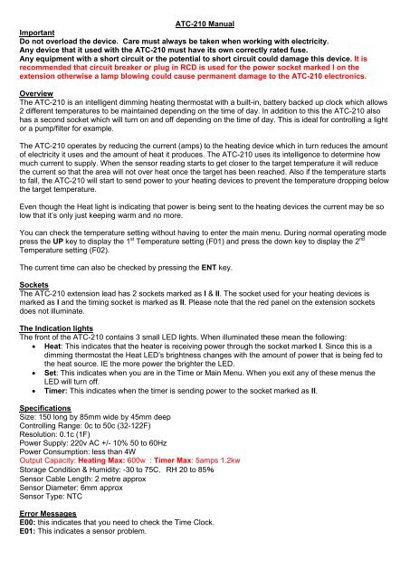
<strong>ATC</strong>-<strong>210</strong> <strong>Manual</strong><br />
<strong>Important</strong><br />
<strong>Do</strong> <strong>not</strong> <strong>overload</strong> <strong>the</strong> <strong>device</strong>. Care must always be taken when working with electricity.<br />
Any <strong>device</strong> that it used with <strong>the</strong> <strong>ATC</strong>-<strong>210</strong> must have its own correctly rated fuse.<br />
Any equipment with a short circuit or <strong>the</strong> potential to short circuit could damage this <strong>device</strong>. It is<br />
recommended that circuit breaker or plug in RCD is used for <strong>the</strong> power socket marked I on <strong>the</strong><br />
extension o<strong>the</strong>rwise a lamp blowing could cause permanent damage to <strong>the</strong> <strong>ATC</strong>-<strong>210</strong> electronics.<br />
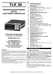
Overview<br />
The <strong>ATC</strong>-<strong>210</strong> is an intelligent dimming heating <strong>the</strong>rmostat with a built-in, battery backed up clock which allows<br />
2 different temperatures to be maintained depending on <strong>the</strong> time of day. In addition to this <strong>the</strong> <strong>ATC</strong>-<strong>210</strong> also<br />
has a second socket which will turn on and off depending on <strong>the</strong> time of day. This is ideal for controlling a light<br />
or a pump/filter for example.<br />
The <strong>ATC</strong>-<strong>210</strong> operates by reducing <strong>the</strong> current (amps) to <strong>the</strong> heating <strong>device</strong> which in turn reduces <strong>the</strong> amount<br />
of electricity it uses and <strong>the</strong> amount of heat it produces. The <strong>ATC</strong>-<strong>210</strong> uses its intelligence to determine how<br />
much current to supply. When <strong>the</strong> sensor reading starts to get closer to <strong>the</strong> target temperature it will reduce<br />
<strong>the</strong> current so that <strong>the</strong> area will <strong>not</strong> over heat once <strong>the</strong> target has been reached. Also if <strong>the</strong> temperature starts<br />
to fall, <strong>the</strong> <strong>ATC</strong>-<strong>210</strong> will start to send power to your heating <strong>device</strong>s to prevent <strong>the</strong> temperature dropping below<br />
<strong>the</strong> target temperature.<br />
Even though <strong>the</strong> Heat light is indicating that power is being sent to <strong>the</strong> heating <strong>device</strong>s <strong>the</strong> current may be so<br />
low that it’s only just keeping warm and no more.<br />
You can check <strong>the</strong> temperature setting without having to enter <strong>the</strong> main menu. During normal operating mode<br />
press <strong>the</strong> UP key to display <strong>the</strong> 1 st Temperature setting (F01) and press <strong>the</strong> down key to display <strong>the</strong> 2 nd<br />
Temperature setting (F02).<br />
The current time can also be checked by pressing <strong>the</strong> ENT key.<br />
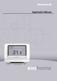
Sockets<br />
The <strong>ATC</strong>-<strong>210</strong> extension lead has 2 sockets marked as I & II. The socket used for your heating <strong>device</strong>s is<br />
marked as I and <strong>the</strong> timing socket is marked as II. Please <strong>not</strong>e that <strong>the</strong> red panel on <strong>the</strong> extension sockets<br />
does <strong>not</strong> illuminate.<br />
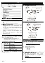
The Indication lights<br />
The front of <strong>the</strong> <strong>ATC</strong>-<strong>210</strong> contains 3 small LED lights. When illuminated <strong>the</strong>se mean <strong>the</strong> following:<br />
• Heat: This indicates that <strong>the</strong> heater is receiving power through <strong>the</strong> socket marked I. Since this is a<br />
dimming <strong>the</strong>rmostat <strong>the</strong> Heat LED’s brightness changes with <strong>the</strong> amount of power that is being fed to<br />
<strong>the</strong> heat source. IE <strong>the</strong> more power <strong>the</strong> brighter <strong>the</strong> LED.<br />
• Set: This indicates when you are in <strong>the</strong> Time or Main Menu. When you exit any of <strong>the</strong>se menus <strong>the</strong><br />
LED will turn off.<br />
• Timer: This indicates when <strong>the</strong> timer is sending power to <strong>the</strong> socket marked as II.<br />
Specifications<br />
Size: 150 long by 85mm wide by 45mm deep<br />
Controlling Range: 0c to 50c (32-122F)<br />
Resolution: 0.1c (1F)<br />
Power Supply: 220v AC +/- 10% 50 to 60Hz<br />
Power Consumption: less than 4W<br />
Output Capacity: Heating Max: 600w : Timer Max: 5amps 1.2kw<br />
Storage Condition & Humidity: -30 to 75C,RH 20 to 85%<br />
Sensor Cable Length: 2 metre approx<br />
Sensor Diameter: 6mm approx<br />
Sensor Type: NTC<br />
Error Messages<br />
E00: this indicates that you need to check <strong>the</strong> Time Clock.<br />
E01: This indicates a sensor problem.
Operating Instructions<br />
There are 2 different menus which are accessed in different ways.<br />
Time Clock: The clock is set in hours and minutes. To set <strong>the</strong> time clock press and hold <strong>the</strong> ENT key for<br />
approx 3 seconds. The display will change to read HUr. If you now press <strong>the</strong> SET key it will display <strong>the</strong> current<br />
hour setting in 24 hour format (ie 0 to 23). Using <strong>the</strong> UP and <strong>Do</strong>wn keys select <strong>the</strong> current hour. Once you<br />
have selected <strong>the</strong> correct hour press <strong>the</strong> SET key again to accept this.<br />
The <strong>ATC</strong>-<strong>210</strong> will now automatically move onto <strong>the</strong> minutes setting by displaying nin. Again using <strong>the</strong> UP and<br />
<strong>Do</strong>wn keys select <strong>the</strong> minute from 0 to 59. Once selected press <strong>the</strong> SET again. Now to save and store <strong>the</strong>se<br />
new time changes you must press and hold <strong>the</strong> ENT key of approx 3 seconds. If no key is pressed for 30<br />
seconds <strong>the</strong> new time will <strong>not</strong> be saved.<br />
Main Menu: This menu is where you set up <strong>the</strong> rest of <strong>the</strong> settings as below. The code in <strong>the</strong> left hand column<br />
is <strong>the</strong> code <strong>the</strong> <strong>ATC</strong>-<strong>210</strong> will display so that you know what option you are changing.<br />
Code Description Range<br />
F01 1 st Time Temperature Setting 0-50c (32-122F)<br />
F02 2 nd Time Temperature Setting 0-50c (32-122F)<br />
F03 Temperature Alarm 0-15c (0-27F)<br />
F04 Calibration 0-15c (-18-18F)<br />
F05 Celsius or Fahrenheit 0 or 1<br />
F06 1 st Time Temperature Setting Start Hr.10Min<br />
F07 1 st Time Temperature Setting End Hr.10Min<br />
F08 1 st Timer Start Time Hr.10Min<br />
F09 1 st Timer End Time Hr.10Min<br />
F10 2 nd Timer Start Time Hr.10Min<br />
F11 2 nd Timer End Time Hr.10Min<br />
To enter <strong>the</strong> Main Menu press and hold <strong>the</strong> SET key for approx 3 seconds and <strong>the</strong> display will read F01. From<br />
here you use <strong>the</strong> UP and <strong>Do</strong>wn keys to select <strong>the</strong> F code for <strong>the</strong> setting you wish to change. Once you have<br />
selected <strong>the</strong> F code you wish to change you <strong>the</strong>n press <strong>the</strong> SET key again to show that setting. Then simply<br />
use <strong>the</strong> UP and <strong>Do</strong>wn keys to change <strong>the</strong> setting. Once you’re happy with <strong>the</strong> setting press <strong>the</strong> SET key again<br />
to accept it. The display will now read <strong>the</strong> next F code on <strong>the</strong> list.<br />
Repeat this process until you are happy with all <strong>the</strong> settings. Now to save and store <strong>the</strong>se new settings you<br />
must press and hold <strong>the</strong> ENT key for approx 3 seconds. If no key is pressed for 30 seconds <strong>the</strong> new settings<br />
will <strong>not</strong> be saved.<br />
Menu Settings<br />
Please <strong>not</strong>e that all <strong>the</strong> time setting on <strong>the</strong> Main Menu are changed in Hours and 10 minutes intervals, in o<strong>the</strong>r<br />
words you can only set <strong>the</strong> minutes in 10 minutes steps (i.e. 00,10,20,30,40 & 50)<br />
For example 6:20 in <strong>the</strong> evening is displayed as “18.2” and 8:50 in <strong>the</strong> evening is displayed as “20.5”<br />
Also you will <strong>not</strong>ice that <strong>the</strong>re is only a 1 st Time Temperature Setting Start & End (F06 & F07) and <strong>not</strong> one<br />
for <strong>the</strong> 2 nd Time Temperature Setting Start & End. This means that any time during <strong>the</strong> 1 st Time<br />
Temperature Setting Start & End setting (F06 & F07) is classed as <strong>the</strong> 1 st time setting and, any time out with<br />
that setting is simply classed as <strong>the</strong> 2 nd Time Temperature Setting. So as soon as <strong>the</strong> 1 st Time Temperature<br />
Setting End (F02) time is reached it <strong>the</strong>n automatically becomes <strong>the</strong> 2 nd Time Temperature Setting Start.<br />
This will continue as <strong>the</strong> 2 nd Time Temperature Setting until <strong>the</strong> 1 st Time Temperature Setting Start time is<br />
reached.
F01- 1 st Time Temperature Setting: Sometimes called <strong>the</strong> Day Temperature Setting. When you have<br />
configured <strong>the</strong> time 1 st Time Temperature Setting Start & End (F06 & F07) this is <strong>the</strong> temperature that your<br />
heat source will heat to during <strong>the</strong>se times.<br />
F02 - 2 nd Time Temperature Setting: Sometimes called <strong>the</strong> Night Temperature Setting. When you have<br />
configured <strong>the</strong> time 1 st Time Temperature Setting Start & End (F06 & F07) this is <strong>the</strong> temperature that your<br />
heat source will heat to out with <strong>the</strong>se times.<br />
F03 - Temperature Alarm: This setting is <strong>the</strong> difference in temperature above or below <strong>the</strong> current<br />
Temperature setting (F01 or F02) as to when a warning alarm will sound. If set to 0 <strong>the</strong> alarm function is<br />
cancelled. For example if your current setting is 25c and you have <strong>the</strong> Temperature Alarm set to 5c <strong>the</strong>n, <strong>the</strong><br />
alarm would sound if <strong>the</strong> temperature reached 30c (i.e. Temperature Setting + Temperature Alarm) or if it<br />
reached 20c (i.e. Temperature Setting minus Temperature Alarm). The alarm will stop sounding by itself when<br />
<strong>the</strong> temperature is back within its tolerance or it can be silenced by pressing any key on <strong>the</strong> <strong>ATC</strong>-<strong>210</strong>.<br />
There is a 10 minute delay in <strong>the</strong> alarm sounding only when <strong>the</strong> <strong>ATC</strong>-<strong>210</strong> is changing from operating between<br />
Time Temperature Setting to Time Temperature Setting. This delay is to stop any alarm sounding and to<br />
give <strong>the</strong> temperature a chance to adjust to its new settings.<br />
F04 – Calibration: Here you can adjust <strong>the</strong> current reading to compensate for any interference that <strong>the</strong> <strong>ATC</strong>-<br />
<strong>210</strong> may pick up from o<strong>the</strong>r equipment. This also allows you to extend <strong>the</strong> sensor cable and adjust <strong>the</strong><br />
temperature reading to compensate for any differences that a longer cable may create.<br />
F05 - Celsius or Fahrenheit: Select 0 to operate in Celsius and 1 to operate in Fahrenheit.<br />
F06 - 1 st Time Temperature Setting Start: As explained at <strong>the</strong> top of this section (Menu Settings) <strong>the</strong> time is<br />
entered in hours and 10 min intervals. This is <strong>the</strong> starting time of <strong>the</strong> 1 st Time Temperature Setting.<br />
F07 - 1 st Time Temperature Setting End: As explained at <strong>the</strong> top of this section (Menu Settings) <strong>the</strong> time is<br />
entered in hours and 10 min intervals. This is <strong>the</strong> end time of <strong>the</strong> 1 st Time Temperature Setting.<br />
All times before F06 & after F07 are classed as <strong>the</strong> 2 nd Time Temperature Setting.<br />
F08 to F11: Relates to <strong>the</strong> timer: These are set in hours and 10 min intervals as explained at <strong>the</strong> top of this<br />
section (Menu Settings). F08 is <strong>the</strong> time you would like <strong>the</strong> timer socket (marked as II on <strong>the</strong> socket) to turn on<br />
at and F09 is <strong>the</strong> Finish Time that you would like it to turn off at. If you only require 1 On and Off time <strong>the</strong> just<br />
ensure that <strong>the</strong> 2 nd time settings (F10 & F11) are programmed to start and end before <strong>the</strong> end time of <strong>the</strong> first<br />
setting (F09). In o<strong>the</strong>r words if you have F09 set to end at 8 o’clock at night <strong>the</strong>n just make sure <strong>the</strong> 2 nd time<br />
settings (F10 & F11) are programmed to both start and finish before 8 o’clock at night and <strong>the</strong> <strong>ATC</strong>-<strong>210</strong> will<br />
only use <strong>the</strong> 1 st time settings.<br />
Specifications<br />
Size: 150 long by 85mm wide by 45mm deep<br />
Controlling Range: 0c to 50c (32-122F)<br />
Resolution: 0.1c (1F)<br />
Power Supply: 220v AC +/- 10% 50 to 60Hz<br />
UK Standard Plug & Sockets<br />
Power Consumption: less than 4W<br />
Output Capacity: Heating Max: 600w & Timer Max: 5amps 1.2kw<br />
Storage Condition & Humidity: -30 to 75C,RH 20 to 85%<br />
Sensor Cable Length: 2 metre approx<br />
Sensor Diameter: 6mm approx<br />
Sensor Type: NTC