EUROSTER 11B - Logitron
EUROSTER 11B - Logitron
EUROSTER 11B - Logitron
- No tags were found...

Create successful ePaper yourself
Turn your PDF publications into a flip-book with our unique Google optimized e-Paper software.
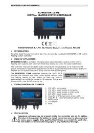
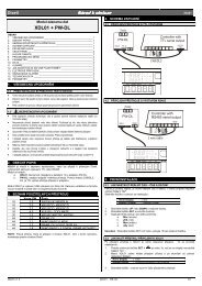
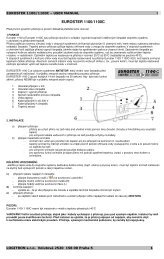
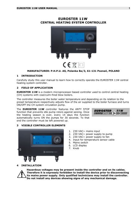
<strong>EUROSTER</strong> 11W USER MANUAL 1<strong>EUROSTER</strong> 11WCENTRAL HEATING SYSTEM CONTROLLERMANUFACTURER: P.H.P.U. AS, Polanka 8a/3, 61-131 Poznań, POLAND1 INTRODUCTIONCarefully study this user manual to learn how to correctly operate the <strong>EUROSTER</strong> 11W centralheating system controller.2 FIELD OF APPLICATION<strong>EUROSTER</strong> 11W is a modern microprocessor-based controller used to control central heating(CH) systems with coal/culm-fired blow boilers.The controller measures the boiler water temperature and depending on its relation to thepreset temperature respectively adjusts flow of the air supplied to the boiler furnace and turnsON/OFF the CH system circulation pump.The <strong>EUROSTER</strong> 11W controller features the ANTY STOPfunction that prevents idle pump rotors against seizing. Oncethe heating season is over, every 14 days the functionautomatically turns ON the pumps for 30 seconds. To thatend the controller must be left powered up.3 VISIBLE CONTROLLER ELEMENTS1. 230 VAC~ mains input2. 230 VAC~ power supply to pump3. 230 VAC~ power supply to fan4. Input for temperature sensor cable5. Mains switch6. LCD display7. Knob4 INSTALLATIONHazardous voltages may be present inside the controller and on its cables.Therefore it is expressly forbidden to install the device prior to disconnectingits mains power supply. Only qualified technicians may install the controller.Do not install any devices showing signs of any mechanical damage.
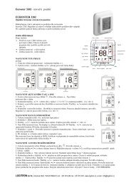
<strong>EUROSTER</strong> 11W USER MANUAL 38. Menu option number (displayed while set point values are browsed/set)9. Boiler temperature / other displayed parameter valueAnimated icon that visually presents state of the boiler furnace.• Firing up – the boiler has not yet reached its preset temperature:-> -> ->• Normal operation – boiler temperature within hysteresis corridor around thepreset:• Blowdown – boiler temperature has exceeded the preset by more than half ofthe hysteresis:• Overheating – boiler temperature >90ºC:• Furnace put out – the preset has not been attained in spite of 1 hour of firingthe boiler up or boiler furnace temperature has dropped below the put-out temperature (setpoint Błąd: Nie znaleziono źródła odwołania):6 TURNING THE CONTROLLER ONTurn the controller mains switch (5 in section 3) into the “I” position. Device firmware version No. and compilation date are sequentially displayed for 2 s. “AS” letters are blinking on the display while the ANTY STOP function turns on thepump. State of the system is shown on the display.If the controller is being turned on for the first time: set the desired controller presets(see section 8 below).7 FACTORY (DEFAULT) PRESETSProceed as follows to restore factory presets:Press the knob and while holding it depressed turn the controller off and on.”Fd” (factory defaults) is displayed.
<strong>EUROSTER</strong> 11W USER MANUAL 4Release the knob. Digit 0 is displayed.Select digit 1 and accept the selection.Check and correct the presets if needed.8 CONTROLLER PRESETSShortly after power supply of the controller is turned on, current state of the system is shownon the display. Turn the knob to the right to enter the preset browse/edit mode. Generalprocedure to edit a preset:1. Turn the knob to select the desired preset (parameter). The controller displays currentvalue of the selected parameter (top) and its number (bottom).2. Press the knob. The displayed parameter value starts to blink.3. Set the desired new value and press the knob to accept itorWait 10 seconds until the displayed parameter value stops blinking in order to abort theedit procedure (to leave the current value intact)Configuration windows are numbered to facilitate manipulations. User may edit the followingcontroller parameters (presets):1. Boiler preset temperatureThe controller will attempt to maintain this temperature manipulating boiler fan and CHpump.2. Fan hysteresisTemperature range, in which controller linearly adjusts fan power. The narrower thepreset hysteresis, the smaller fluctuations of the CH system temperature will be.However, a too narrow preset will make the temperature to oscillate – the controller willalternately heat up and cool down the boiler.Initially set the maximum allowable hysteresis, wait until the preset temperature isreached and check if (in such conditions) the fan operates at a power level between setpoints Błąd: Nie znaleziono źródła odwołania and Błąd: Nie znaleziono źródła odwołania.If so, the hysteresis may be narrowed down.3. Minimum fan powerThe lowest power at which the fan may operate. Should be selected experimentally asthe power, at which the fan rotor starts to rotate (see fan test function, set point 11).4. Maximum fan powerThe highest power at which the fan should operate. Should be selected experimentallyas the power, at which the actual boiler temperature (maintained by the controller) wasas close to the preset temperature as possible.5. Blowdown timeThe fan is turned ON for that period if the controller needs to blow down the furnace (toremove combustion gases out of the boiler). Blowdown time should be long enough toeffectively exhaust the gases via the chimney, but on the other hand short enough toprevent boiler temperature rise.6. Gap between successive blowdownsTime after the last blowdown cycle before a new cycle may be started. It should be longenough to prevent boiler temperature rise, but on the other hand short enough to avoidexplosive combustion of the boiler gases.7. CH pump TURN ON temperatureSee section 11 for detailed description of conditions in which CH pump is turnedON/OFF.8. CH pump hysteresisDifference between the temperature at which the controller turns the pump on and thetemperature at which the controller turns it off. See section 11 below for details.
<strong>EUROSTER</strong> 11W USER MANUAL 59. Boiler temperature sensor correctionA constant added to all values measured by boiler temperature (external) sensor tocompensate for differences in respect to water temperature inside the boiler.10.Put out temperatureAs soon as actual boiler temperature has dropped below that preset, the controllerturns the boiler OFF (the boiler furnace is most probably put out). A too high put outtemperature presetmay cause the controller to turn the boiler OFF mistakenly.11.Fan manual operation (test)Display current fan status commanded by the controller (0…100%). Press the knob andmodify the parameter value to manually control the fan. Press the knob once more orleave it inactive for 10 seconds to resume automatic mode of control.12.Pump manual operation (test)Display current pump status commanded by the controller (0/1 = pumpdisengaged/engaged).Press the knob and modify the parameter value to manually control the pump. Pressthe knob once more or leave it inactive for 10 seconds to resume automatic mode ofcontrol.All controller presets are listed below:ParameterPreset valueNo. Name default min maxUnit1 Boiler preset temperature 50 40 80 °C2 Fan hystersis 6 2 10 °C3 Minimum fan power 45 30 100 %4 Maximum fan power 100 30 100 %5 Blowdown time 10 0 120 s6Gap between successiveblowdowns6 0 30 min7 CH pump TURN ON temperature 40 20 80 °C8 CH pump hysteresis 4 2 10 °C9Boiler temperature sensorcorrection0 -5 5 °C10 Put out temperature 35 30 50 °C11 Fan manual operation (test) – 1) 0 (OFF) 100 (ON) %12 Pump manual operation (test) – 1) 0 (OFF) 1 (ON) -1) The controller displays values calculated by its algorithm.9 FIRING UPDuring the boiler firing-up phase the pump is disengaged and the fan is operated at its highestpower level in order to speed the process up as far as possible.The firing up procedure may be initiated exclusively while the controller is in the putoutmode – fan is not operating, no flame icon is visible on the display.To initiate the procedure: turn the controller knob all the way to the left, then press it and hold down until the fanis started, or turn the controller power OFF then ON.The procedure is terminated when: the boiler temperature is closer to the preset (Błąd: Nie znaleziono źródła odwołania)than half of the hysteresis (Błąd: Nie znaleziono źródła odwołania, )or within 1 hour the boiler has not reached the preset put-out temperature (Błąd: Nieznaleziono źródła odwołania).If for any reason (e.g. self firing up) the temperature of a put-out boiler exceeds the presetput-out temperature (Błąd: Nie znaleziono źródła odwołania), the controller will automatically
<strong>EUROSTER</strong> 11W USER MANUAL 6resume normal operation i.e. pumps will not be turned OFF.10 FUELINGThe fan should be turned OFF for the time the boiler furnace is loaded with new fuel. To thisend turn the controller knob all the way to the left while the controller is in its normaloperation mode (flame icon visible on the display), then press the knob and hold it down untilthe flame icon disappears. Fan icon starts to blink alternately with a hand icon – it means thatthe fan was manually disengaged (all other algorithms are operating normally).Proceed as above to turn the fan ON. Once the fan is back ON, the controller initiates the firingup cycle – it turns the pump OFF in order to fire the new batch of fuel up as soon as possible.Should the flame to extinct, the controller will automatically turn the fan OFF.ATTENTION: The controller will not automatically turn the fan OFF if it was earliermanually turned OFF by the user and not turned back ON.11 CONTROLLER OPERATIONThe controller attempts to maintain boiler temperature adjusting amount of air blown to thefurnace by the fan and turning the CH pump ON/OFF.Cold boiler may sweat during the firing-up period. Therefore the fan is operating at the highestpower level (preset Błąd: Nie znaleziono źródła odwołania) and the pump is OFF to shortenthat period as far as possible.As soon as the boiler temperature has approached the preset (and is within the hysteresiscorridor), the controller starts to smoothly control air flow adjusting the fan power level. Fanpower range is limited by the minimum fan power (Błąd: Nie znaleziono źródła odwołania) andthe maximum fan power (Błąd: Nie znaleziono źródła odwołania) presets.Should the boiler temperature to exceed the upper threshold, the controller will start the boilerblowdown cycling. In that mode the fan is used only to remove combustion gases out of thefurnace. Blowdown cycle parameters should be set so that boiler temperature will drop downto the level at which the controller will be able to resume linear control of the fan power.Should the boiler temperature to exceed the alarm temperature, the fan will be turned OFF forgood. Overheating is signaled by pulsing of the controller display.Should the boiler temperature to drop down below the put-out preset (Błąd: Nie znalezionoźródła odwołania), the fan will be turned OFF. The pumps will be operated normally.The CH pump is engaged as soon as boiler temperature T boiler exceeds boiler presettemperature T preset by more than half of hysteresis H pump:T boiler > T preset +H pump/2The pump is disengaged as soon as the temperature drops down below the preset by morethan half of the hysteresis:T boiler < T preset – H pump/212 THE ANTY-STOP FUNCTIONThe ANTY-STOP function turns on the pump immediately after the controller is turned on, thenevery 14 days. “AS” letters are blinking on the controller display while the function is active.Any alarm generated while the ANTY-STOP function is active (overheating or temperaturesensor failure) aborts the function execution.13 TROUBLESHOOTINGa) Device is deadBurnt mains fuse or ROM failure. Replace the fuse or have the controller serviced.b) Sensor icon on the display blinks, “Sh” or “OP” letters next to the iconSensor circuit shorted (Sh) or opened (OP). Check/replace the sensor cable or ship thecontroller (together with the sensor) to service.
<strong>EUROSTER</strong> 11W USER MANUAL 9Warranty terms:<strong>EUROSTER</strong> 11W CONTROLLER WARRANTY CERTIFICATE1. Warranty is valid for 24 months from the controller sale date.2. Warranty is valid exclusively on the territory of Poland.3. Claimed controller together with this warranty certificate must be supplied to theseller or directly mailed via Poczta Polska mail operator to the manufacturer.4. Warranty claims shall be processed within 14 business days from the date themanufacturer has received the claimed device.5. Controller may be repaired exclusively by the manufacturer or by other party clearlyauthorized by the manufacturer.6. Warranty becomes invalidated in case of any mechanical damage, incorrectoperation and/or making any repairs by unauthorized persons.7. This consumer warranty does not exclude, restrict nor suspend any right of theBuyer ensuing if the product would not meet any of the sale contract terms.........................................................................................................................sale date serial number/date of manufacture signature/stampService phone (48) 655-71-20-12Business entity that issued this warranty certificate:P.H.P.U. AS Agnieszka Szymańska-Kaczyńska, Chumiętki 4, 63-840 Krobia, Poland