ATR620 - Logitron
ATR620 - Logitron
ATR620 - Logitron
- No tags were found...

You also want an ePaper? Increase the reach of your titles
YUMPU automatically turns print PDFs into web optimized ePapers that Google loves.
<strong>ATR620</strong>
Contents20 Introduction.................................................................................................... 5421 Models........................................................................................................... 5421.1 Ordering codes....................................................................................... 5422 Technical data ............................................................................................... 5522.1 Main features ......................................................................................... 5522.2 Hardware data........................................................................................ 5522.3 Software data......................................................................................... 5623 Sizes and installation...................................................................................... 5624 Electrical wirings ............................................................................................ 5724.1 Wiring plan............................................................................................. 5725 Displays and keys.......................................................................................... 6025.1 Numerical indicators (displays)................................................................ 6025.2 Leds....................................................................................................... 6125.3 Keys ...................................................................................................... 6126 Programming and configuration...................................................................... 6226.1 Programming (or modifying) cycle data ................................................... 6227 Start of a cycle............................................................................................... 6627.1 Cycle start and programming of delaied start........................................... 6627.2 Function “Fast advancement”.................................................................. 6727.3 Function SIMPLE CONTROLLER with cycle in execution ........................ 6727.4 Function SIMPLE CONTROLLER in STOP mode.................................... 6827.5 Auto-tuning............................................................................................. 6927.6 Activate remote setpoint by input 2 ......................................................... 6927.7 Activate remote setpoint by serial input ................................................... 7027.8 Manual control of output ......................................................................... 7128 Configuration for installer................................................................................ 7228.1 Modify numeric value of parameter.......................................................... 7228.2 Modify configuration parameter............................................................... 7228.3 Memory Card ......................................................................................... 7429 List of configuration parameters...................................................................... 7530 Alarms operating............................................................................................ 8631 Special software functions.............................................................................. 8831.1 Recovery of interrupted cycle with automatic gradient.............................. 8831.2 Recovery of interrupted cycle with programmable gradient....................... 8931.3 Waiting function...................................................................................... 8931.4 Double loop: control the gap between processes ..................................... 9032 Communication protocol Modbus RTU............................................................ 9032.1 Main features ......................................................................................... 9032.2 Function Master...................................................................................... 9132.3 Word addresses <strong>ATR620</strong>........................................................................ 9133 Error messages ............................................................................................. 9334 Application on industrial kilns.......................................................................... 9435 Kiln with single thermocouple and SSR control................................................ 9436 Kiln with 2 thermocouples and contactor control.............................................. 9637 Kiln with 4 thermocouples - 4 units <strong>ATR620</strong> Configuration Master/Slave ......... 9838 Configuration table........................................................................................1003
20 IntroductionProgrammers <strong>ATR620</strong> are the results of a wide experience withapplications for temperature and process control by Pixsys(www.pixsys.net ).High configurability of both hardware and software resourcesallows the installer to configure the controller assuring both userfriendlinessfor the operator and at the same time theprogramming of complex and accurate firing profiles.To program a cycle means basically to enter couples of valuestime /temperaure (setpoint) for each segment of the cycle. Eachcontroller can be connected to one or two sensors; the outputoptions include relays and SSR control. Other resources areavailable for the management of alarms, auxiliary and digitalcommands. Possibility to integrate the unit into supervisorysystems or communication networks is assured by RS485 andprotocol Modbus-RTU with Master/Slave modality.Memory card allows to quickly copy parameters and cycle data,keeping record of the different configurations.**Chapters 26.1 and 27.1 specifically focus on the operatinginstructions for the users.21 ModelsThe series <strong>ATR620</strong> includes two versions: the following tableallows to choose the correct model.21.1 Ordering codes<strong>ATR620</strong>- o o oInputs 2 2 Inputs TC-RTD-V/mAOutputs1 2 relays + 1 output SSR2 3 relaysPower supply ABC 24/230/115Vac ±15% 50/60Hz54
22 Technical data22.1 Main featuresVisualizers 4 displays 0,56 inches4 displays 0,28 inchesOperating temperature 0-45°C, humidity 35..95uR%Sealing IP54 Frontal, IP30 box, IP20 terminalsblockMaterial Noryl 94V1 self-extinguishingWeight 400g22.2 Hardware dataAnalog input 1: AN1, AN2Software configurableInput An. 1Thermocouple K, S, T, R, J, ERTD type PT100, Ni100Input An. 2Thermocouple K, S, T, R, J, EInput 0-1V, 0-10V,0-20mA, 4-20mARelay outputs 2/3 relays: OUT, A1, (A2)Configurable for command oralarmSSR output 1 output: A2Configurable for command oralarmAccuracy(25°C)0.2 % ± 1 digitfor input TC,RTD , V, mAContacts 8A-250V~Output 12Vdc30mASerial input 1: RS485 , Modbus protocolDigital input 1: IN1, IN2Configurable as Input START/STOP, signal, HOLD input55
22.3 Software dataControl algorithm ON-OFF with hysteresis,P, PI, PID, PD time proportioningProportional band 0...9999°C or °FIntegral time 0...9999 sec (0 excludes)Derivative time 0,0...999,9 sec (0 excludes)Software functions Auto-Tuning , configurable alarmsProgrammablecycles15 cycles, max 20 segments (steps) foreach cycle + function “simple controller”with programmable setpointRemote control Setpoint received by analog or serial inputManual function Increase/decrease manually the percentageof output (manual control of power)23 Sizes and installation56
24.1 Wiring diagram24 Electrical wiringsAltough this controller has been designed to resistnoises in an industrial environment, please notice thefollowing safety guidelines:• Separate control wires from power wires• Avoid mounting close to remote control switchingsystems, electromagnetic relays, powerfulengines• Avoid proximity of power systems, especiallythose with phase control57
Power supply24/115/230Vac ±15% 50/60Hz(selction by internal jumper)Default selection: 230 VoltVersion <strong>ATR620</strong>-xxABCSet SW1 as in the drawing beside to selectproper power supplyAnalog input AN1PT 100NI100Thermocouples type K, S, T, R, J, E• Respect polarity• When extending thermocouples be sure touse the correct extension/compensatingcablePT100, NI100• For a three-wire wiring use cables withthe same diameter• For two-wire wiring, short-circuitterminals 14 and 15321Analog input AN2Thermocouples type K, S, T, R, J, E• Respect polarity• When extending thermocouples be sure touse the correct extension/compensatingcableSignals 0-1V, 0-10V, 0-20mA, 4-20mA• Respect polarity58
Signals 0/4….20mA with 3-wires sensorOUT : 4...20mAIN :9...33V DCP :0...100mbarPmax :3barT :0..70°CRespect polarityA=Sensor outputB=Sensor groundC=Sensor supplySignals 0/4….20mA with 2-wires sensorOUT : 4...20mAIN :9...33V DCP :0...100mbarPmax :3barT :0..70°CRespect polarityA=Sensor outputC=Sensor supplySerial or digital inputConfigurable as serial input or two digitalinputs• RS485 ModbusRelay / SSR outputsContact capacity 8A/250V~ resistive• Configurable as command or alarm• Configurable as N.O. or N.C.Contact capacity 8A/250V~ resistive• Configurable as command or alarm• Configurable as N.O. or N.C.Version <strong>ATR620</strong>-21ABC:• Capacity 12V/30mAVersion <strong>ATR620</strong>-22ABC:• Contacts capacity 8A/250V~ resistiveConfigurable for control or alarm N.O. or N.C.59
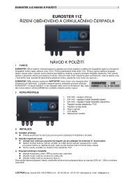
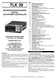
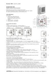
25 Displays and keys53749612118101225.1 Numerical indicators (displays)Visualize usually process value (ex. Value1read by thermocouple), but may alsovisualize setpoint value, time elapsed aftercycle start 1 , step number 2 , percentagevalue of output , value of entering parameterGREEN during configuration 15 .Visualization on this dispay is programmable2and may be chosen as setpoint value,elapsed time or step/cycle in progress.Visualize number of entering parameterRED during configuration. VisuaIize Step-time(ex.:01-T) or step-setpoint (ex.:01-S) which isbeing entered during cycle programming.1 Example for 1 hour, 5 minutes2 Example for step no. 315 See chap.2660
25.2 Leds3 ON when output OUT is active4 ON when output A1 is active5 ON when output A2 is active6 ON with cycle in progress, flashing if function “Simplecontroller” in progress, remote setpoint, manual control,serial communication.25.3 Keys7 • Scroll or modify parameters during configuration• Scroll available cycles (to start or modify)• Modify time or setpoint values when programming cycles• Modify setpoint when function “Simple controller” (TERM)is working• Fast advancement with cycle in progress8 • Scroll or modify parameters during configuration• Scroll available cycles (to start or modify)• Modify time or setpoint values when programming cycles• Modify setpoint when function “Simple controller” (TERM)is working• Fast go back with cycle in progress9 • Visualize duration of latest completed cycle if controlIer is inSTOP mode• Second process only if enabled• Scroll flashing digit to modify values during configuration ofparameters• With cycle in progress, visualize (cycling) setpoint value and ifconfigured also other data.10 • Enter list of available cycles or configuration mode when thecontroller is in STOP mode• Press it for more than 1 second to enter functions menu withcycle in progress11 • Start new cycle or stop cycle in progress• ESCAPEkey when the controller is in configuration mode12 • Confirm entered value or selected function61
26 Programming and configurationThere are two different levels of programming :1. Programming of cycles (for operator/user) means entering oftime/setpoint values for each step/segment of cycle.2. Configuration (for manufacturer/installer of plant) means enteringof basic parameters (sensor type, outputs functioning, operating ofauxiliary output ..).26.1 Programming (or modifying) cycle dataWith or without starting setpoint, with or without timedauxiliary outputs ******The above specifications underline the possibility given to theinstaller (plant’s manufacturer) to choose the sequence ofoperations required for the programming of a firing cycle.This paragraph includes all available options. In case that theinstaller decides to chose a simplified programming with lessoptions, it is highly recommended to prepare additional/separateinstructions specifying only the selected sequence. The file of thisparagraph is available in the Download section at www.pixsys.netand it may be used for this purpose.Set the controller tomode and follow the points belowPress Display Do1 Red display shows.2 Increase or decrease tovisualize visualizzareup to15.for cycle no.1for cycl no.2for cycle no.62
26.1.1 Programming of starting set-point (if configured)Press Display Do3 Red display shows16 or , then(see configuration ofvisualization Par.19, 4 thdigit).Green display shows the“starting setpoint”.Otherwise go to point 5.4 Increase/decrease value ongreen display.At any time pressto quit the programmingmode and savemodified data..Enter starting setpoint(ex. Temperature atcycle start)16 The first two digits indicate number of step. Last digit shows entering thetime value/duration of step or entering setpoint value (ex.:temperature valueto reach within the programmed time)63
26.1.3 Programming of auxiliary output (if configured)Press Display Do8 Green display showsor .If output A1 is notprogrammed as timedauxiliary, go to point 10.9 Select the state ofauxiliary output duringthe step:active oractiveforfor not10 Green display shows If output A2 is notor .programmed as timedauxiliary, go back topoint 511 Select the state ofauxiliary output duringthe step:foractive or for notactive .Go back to point 5.26.1.4 End of programming…Press Display Do12 The controller returnsto STOP mode,storing theprogrammed cycle.Red displayIn case that outputs (A1, A2)are programmed asauxiliaries, repeat points 9and 11 to program the stateof outputs after cycle stop.shows .65
27 Start of a cycle27.1 Cycle start and programming of delaied startRed display shows .Press Display Do1 Red display showsavailable cycles2 Increase or decreaseuntil the chosen cycle isvisualized(for cycle no.1),(for cycleno.2)...3 Cycle starts. Buzzeror rings. Green displayshows process value, reddisplay shows the valuewhich has been selectedon P-51, 1 st digitIf function “Delayed start” is enabled (see P-01, 2 nd digit)follow the table below4 Red display showsor , green displayshows flashing theprogrammed time.5 Increase or decrease thewaiting time after cycleStart (Hours:Minutes).6 Start of waiting time. Atelapsing of programmedtime, cycle will start..Press to modifytime value66
27.2 Function “Fast advancement”During cycle execution or in case of restart after an interruption, itmay be useful to change the programmed time value of therunning cycle (onwards or backwards) to meet the requiredsetpoint.Press Display Do1 Forwards or backwards on To stop the cycle and setcycle (each beep of the controller ininternal buzzer means one mode before end of cycleminute).press .27.3 Function SIMPLE CONTROLLER 17 with cycle inexecutionThis function can be activated during cycle execution.Press Display Do1 Red display showsflashing.Keep pressing the keyfor approx. 1 second.2 Red display shows. The controlleractivates the output to holdthe programmedtemperature3 Modify setpoint value. Reddisplay shows andgreen display shows newsetpoint for a few seconds.To quit the function press(the controller returns to thethe cycle which waspreviously in execution).17 Access to this function can be denied to the operator on P-01, 2 nd digit67
27.4 Function SIMPLE CONTROLLER in STOP mode.Set the controller tomode.Press Display Do1 Red display showsavailable options2 Increase until isvisualized3 Red display shows, Green displayshows setpoint value.4 Increase or decreasesetpoint valueEnter required setpointvalue.5 The controller activatesthe output to hold theprogrammedtemperature..6 Values are visualizedcycling.To modify setpointpressand/or arrowkeys (againand arrowkeys for )To quit the function press.68
27.5 Auto-tuningAuto-tuning 18 function can be started if the controller is configuredas SIMPLE CONTROLLER.Process value must be at least 35% lower than setpoint value(to avoid overshooting of temperature above setpoint value). If twoprocess are enabled, please go to P-19/1 st digit, to choose theprocess to which Autotuning will refer.Press Display Do1 is flashing on redKeep pressing for 1 second.display.2 Red display showsThe controller starts theself-calibration cycle27.6 Activate remote setpoint by input 2 19Set the controller toWait until the writingdisappers. To stop thefunction before it iscompleted, press .mode and follow the points below.Press Display Do1 Red display shows availableoptions.2 Increase or decrease untilis visualized3 Green display shows processvalue. The controller activatescontrol output.To quit the function press18 Access to this function can be denied to the operator on P-01, 2 nd digit19 To configurate this function, select 0 (remote setpoint) on 4 th digit of P-01and “ Remote setpoint by analog input AN2” on 4 th digit of P-05.69
27.7 Activate remote setpoint by serial input 20Set the controller to mode.To start the function by serial input, write 1 at modbus address 15:this operation must be repeated at least every 8 seconds,otherwise the controller will return to modeTo quit the function write 0 at the same address.Setpoint values must be entered at Modbus address 9 forprocess 1 and at address 10 for process 2.20 To configurate this function, select 0 (remote setpoint) on 4 th digit of P-01and “ Remote setpoint by analog input AN2” on 4 th digit of P-0570
27.8 Manual control of output 21This functions allows to control/modify manually the commandoutput to exclude automatical control of process. The output isactivated as percentage 0 - 100% according to the time basisentered on parameter P-30 (cycle time).Set the controller tomode and follow the points below:Press Display Do1 Red display showsavailable options2 Increase/decrease untilis visualized3 Green display showspercentage of outputThecontroller activates theoutput.4 Visualize percentage valueof output 1 (cycling alsovalue of output 2 ifenabled).To modify percentagepress funtil reddisplay shows(or if twoprocess are enabled)and press tomodify value.To quit the function press21 Access to this function can be denied on P-01, 3 rd digit.71
28 Configuration for installer28.1 Modify numeric value of parameterThe following options are available :1. If all 4 digits are flashing, press to change theparameter.2. If all 4 digits are visualized but only one is flashing, pressto modify it and then to reach the following digit .28.2 Modify configuration parameterTo modify configuration parameters (see chap. 29), the controllermust be inmode.Press Display Do1 Red display shows availableoptions2 Increase/decrease until3 Green display shows4+and 1 st digit isflashing. Red display shows.Modify the flashing digit ongreen displayEnteris visualizedpassword72
Press Display Do5 Red display shows, green displayshows value of parameter6 Increase / decrease numberof parameterVisualize number ofparameter which mustbe modified7 Green display shows theflashing value of selectedparameter.8 Increase / decrease valueof visualized parameter.Enter new value9 Value of parameter stopsflashing10 End of configuration.The controller is inmode.** If Memory Card isconnected, its values will beup-dated with new datawithin a few seconds.To modify otherparameters go back topoint 6.73
28.3 Memory CardParameters and cycle data can be easily and quickly copied fromone controller to other controllers using the Memory Card. Thecontroller must be switched off before entering the Card.Please check also entry direction : the small scanning must beturned towards the back panel and the small IC must be turnedtowards the external side of the box. When the controller isswitched-on, the green display shows22 .and the red displayshowsPress Display Do1Select to loadvisualize ,values of memory cardvisualize .on the controller.Select to keepvalues of the controllerunchanged.2 The controller loads thevalues and starts the selfcheckTo update values of MemoryCard, follow the above describedoperations selecting on reddisplay so that values of Card are notloaded on the controller23 . Enterconfiguration mode and modify atleast one parameter. Quitting theconfiguration mode, a beep of internalbuzzer will confirm that the newvalues are saved.22 Only if values stored on Memory are correct23 If the controller shows at starting, it means that no values arestored on memory, but it is possible to copy and update them74
29 List of configuration parametersP-01 General configurationThis parameter selects the type of P.I.D. action, enablesoperator’s access to special functions like manual control ofoutput percentage 0-100%, Autotuning, delayed start, operatingas “Simple controller” with fixed setpoint beside standardprogramming function, possibility to modify cycle data during thecycle, programming of a starting setpoint (to assure theprogrammed rising gradient in case that kiln temperature at cyclestart is too high), number of cycles available to the operator,remote control for cascade applications..1 st Digit – Type of PID control0 Single reverse action (Heating)1 Single direct action (Cooling)2nd Digit – Access to following functions:Auto-tuning Simple controller Delaied start0 No No No1 Yes No No2 No Yes No3 Yes Yes No4 No No Yes5 Yes No Yes6 No Yes Yes7 Yes Yes Yes3 rd Digit – Access to following functionsManual % Starting setpointOutput0 No No No1 Yes No No2 No Yes No3 Yes Yes No4 No No Yes5 Yes No Yes6 No Yes Yes7 Yes Yes YesModify data duringthe cycle75
4 th Digit – Cycles available to the operator0 No cycles availableRemote setpoint enabled1…9 1..8 cycles available for the operatorSelect 9 for 15 cycles / 20 steps eachP-02 Configuration analog input AN1Select type of thermocouple or RTD connected to input AN1,visualization range and process corresponding to this input.1 st Digit – Type of sensor0 Not used1 Thermocouple or RTD (selected on 2 nd digit)2 nd Digit – Type of thermocouple/RTD0 Type K (-250/1350°C)1 Type S (-50/1750°C)2 Type T (-250/400°C)3 Type R (-50/1750°C)4 Type J (-200/1000°C)5 Type E (-250/1000°C)6 PT100 (-100/600°C)7 NI100 (-60/180°C)3 rd Digit – Decimal point0 No decimal point1 Visualization with decimal point4 th Digit – Select corresponding process0 Process 11 Process 2P-03 Configuration of analog input AN2Select type of thermocouple or signal V/mA connected to inputAN2, visualization range and process corresponding to this input1 st Digit – Type of sensor0 Not used1 Thermocouple (selected on 2 nd digit)2 Tension 0-1V3 Tension 0-10V4 Current 0-20mA5 Current 4-20mA2 nd Digit – Type thermocouple/RTD0 Type K (-250/1350°C)1 Type S (-50/1750°C)76
2 Type T (-250/400°C)3 Type R (-50/1750°C)4 Type J (-200/1000°C)5 Type E (-250/1000°C)3 rd Digit - Decimal point0 No decimal point1 Visualization with one decimal point2 Visualization with 2 decimal points (only V /mA)3 Visualization with 3 decimal points (only V /mA)4 th Digit – Select process0 Process 1(* ex. Pressure or humidity sensor connected to analog inputAN2 is Process 1)1 Process 2P-04 ReservedP-05 Configuration control outputs and source of setpoints(ex.: TC1 on AN1 configured as process 1 on Out and TC2 onAN2 as process 2 on A1) and select source of setpoint (** OnlySetpoint1 changes according to the programmed cycle, whileSetpoint2 can only be fixed.1 st Digit – Control output process 12 nd Digit – Control output process 20 No output or isabled process1 Relay OUT contact N.O.2 Relay OUT contact N.C.3 Relay A1 contact N.O.4 Relay A1 contact N.C.5 Relay or SSR A2 contact N.O.6 Relay or SSR A2 contact N.C.7 Open/Close contact N.O. (Open OUT, Close A1)8 Open/Close contact N.C. (Open OUT, Close A1)3 rd Digit–Source of setpoint for process 1 + process 2Process 1 Process 20 Setpoint1 (cycle data) Setpoint1 (cycle data)1 Setpoint1 (cycle data) Setpoint2 (fixed)2 Setpoint2 (fixed) Setpoint1 (cycle data)77
4 th Digit – Select remote setpoint0 Remote setpoint by analog input AN2Control input AN11 Setpoint by serial input: process 1 – word modbus 9process 2 – word modbus 10P-06 Lower limit setpoint 1 (-999/3000 digit)P-07 Upper limit setpoint 1 (-999/3000 digit)Selectable limits of setpoint 1P-08 Lower limit range AN2 only for V/mA (-999/3000 digit).P-09 Upper limit range AN2 only for V/mA(-999/3000 digit).Limits of scale (values to visualize if input AN2 is configured asV/mAP-10 Alarms hysteresis (-999/3000 digits).Hysteresis for alarms tresholds.This function is useful to avoiddisturbing oscillations of outputsP-11 Configuration alarm no.1 corresponding to output OUTP-12 Configuration alarm no.2 corresponding to output A1P-13 Configuration alarm no.3 corresponding to output A2These parameters allow to select the operating mode for therelay or SSR outputs when they are not used for process control(see P-05).Beside alarm modes described on chap. 30, available optionsinclude also auxiliary functions related to time (steps), torising/dwell/cooling gradient or to the state of controller (duringcycle execution or at cycle end).Setpoint values (comparison values) must be entered onparameters P-14..16.1 st Digit –Type of operation--- 0 Output not used as alarm/auxiliary/eventALL 1 Independent related to process (3 rd Digit)EVN 2 Active in RUN (N.O. or N.C. selected on 2 nd Digit)ALL 3 Independent related to setpointALL 4 Band (setpoint – process)EVN 5 Active at cycle endALL 6 Deviation (setpoint – process)AUX 7 Timed, related to step (On or Off for each step)AUX 8 Active for rising steps or dwellsAUX 9 Active for cooling steps78
2 nd Digit –Operating zone for alarm and state of contact0 Active “under” (independent or deviation alarm) or“inside” (band alarm), Contact N.O.1 Active “over” (independent or deviation alarm) or“outside” (band alarm), Contact N.O.2 Active “under” (independent or deviation alarm) or“inside” (band alarm), Contact N.C.3 Active “over” (independent or deviation alarm) or“outside” (band alarm), Contact N.C.4…7 As 0, 1, 2, 3 active ONLY in RUN (during cycle)3 rd Digit – Select process for alarm0 Process 11 Process 24 th Digit –Type of alarm action on cycle0 No action on cycle, no acoustic signal of buzzer, novisualization on displayOutput is commuted (change of relay or SSR contact).1 Cycle stop with acoustic and visual signal 24 .Output is commuted, buzzer is activated, display flashes,cycle stops and controller goes to to STOP mode.2 Only acoustic signalOutput is not commuted, buzzer is activated, display flashes.P-14 Setpoint value for alarm no.1-999/3000 digit (°C for temperature)P-15 Setpoint value for alarm no.2-999/3000 digit (°C for temperature)P-16 Setpoint value for alarm no.3da-999/3000 digit (°C for temperature)P-17 Configuration digital input IN1 25P-18 Configuration digital input IN2Operating mode for digital inputs IN1..2. Impulse means contactclosed (or open) for min. 150msec.1 st Digit –Operating mode of digital input0 Input not used24 Visual signal for active alarm is or until is pushedto confirm it.25 Inputs not available if using RS485.79
1 Input START at impulse (>= 150 msec)2 Input STOP at impulse (>= 150 msec)3 Input START/STOP at impulse (>= 150 msec)4 RUN input when active. The controller executes the cycleprogrammed on 3 rd digit (or function selected on 4 th digit)until contact is closed (or open).5 Temporary cycle block, flashing(Normally connected to the door switching).6 Cycle stop with acoustic and visual signal.Visualize for IN1 or for IN2, buzzer isactive until is pressed.7 Input HOLD.Cycle is stopped and setpoint can be modified by frontalkeys.8 Impulse input for step advancement (one step forwards)during cycle.2 nd Digit – Type of contact0 Activation with closed contact1 Activation with open contact3 rd Digit – Function or cycle to activate0 Activate function selected on 4 th digit1…9 Activate cycle no.1…94 th Digit – Special function to activate0 “Simple controller”1 Remote controller (if P-01/ 4 th Digit selected as 0)2 Manual control(modify percentage of control output 0…100%)3 Last executed cycle4 Simple controller (also during cycle execution)P-19 Configuration Auto-tuning and visualization of stepSelect on which process Autotuning will be completed and whichvalues will be visualized in RUN mode.1 st Digit – Configuration Autotuning0 Autotuning only on process 11 Autotuning only on process 22 Autotuning both on process 1 and process 22 nd Digit – Control of heating elements power80
0 Only process11 Only process 22 Add process 1 and process 23 rd Digit – Real time/duration of cycle 260 No1 yes4 th Digit – Visualization of step0 Step number always visualized in programming mode1 Step number visualized only at beginning of step(equivalent to the operating in programming mode of seriesATR610)P-20 Power of heating elements (0.0/999.9 Kwatt).Enter power of heating elements group. If the programmed valueis different from 0, it will be possible to visualize powerconsumption (expressed as Kwatt/hour) at cycle end pressingkeyP-21 Waiting for step end (1/1440 min, 0 excludes waiting function)Enter max. waiting time for step end. For further details see 31.3P-22 Max. gap at step end to activate waiting function(1/200 digit).When the gap setpoint-process 1 is lower than this value, thecontroller jumps to next step of cycle without waiting for the timeentered on P-21. For further details see 31.3P-23 Recovery of interrupted cycleThis parameter enables recovery of interrupted cycle after apower failure. For further details see 31.1-31.20 Cycle recovery isabled1 Cycle recovery enabled (see 31.1)2-9999 Recovery gradient (rising) as degree/hour (see 31.2)P-24 Reserved26 Pressing , during cycle, the visualized time value will be the timeelapsed after cycle start, not the programmed time. PPressingStop to visualize duration of last cycle.81after cycle
P-25 Filter on analog inputs (1/20 averages).Value of software filter which is active on the reading of sensorsconnected to inputs AN1 and AN2.In case of disturbed signals, filter should be increased, reducingreading speed .P-26 Offset calibration for input AN1 (-15.0/15.0 digit)P-27 Gain calibration for input AN1 (-10.0%…+10.0%)These parameters allow to adjust eventual errors onvisualization, caused by damages or mistakes on thermocoupleswirings or compensated cables.Example: if melting point of a ceramic cone is 1000°C while thecontroller shows 990°C, enter 1.0 on P-27 to get the correctvalue on displayP-28 End of ON/OFF control (-999/3000 digit)Below this value, the controller modulates the output as ON/OFFexcluding P.I.D. action. To use only On/off mode, enter a valueabove the upper limit of scale 1. To exclude ON/OFF controlenter a value below the lower limit of scale 1.P-29 ReservedP-30 Max. time for impulse in zone 1 (1/120 sec).This parameters selects cycle time for time-proportioned outputs(PID or manual control of output %).Ex. 10 sec. On P-30 means 60% of output when output is activefor 6.0 seconds/not active for 4.0 seconds and so on.P-31 Limit of command signal for zone 1(10/100%)Max. limit of command signal expressed as %Ex.: Enter 60 on this parameter to allow max. 60% power ofheating elements on electrical kilns.P-32 ReservedP-33 ReservedP-34 ReservedP-35 ON/OFF hysteresis; P.I.D. dead band (-99.9/300.0 digit)P-36 Proportional band (0-3000 digit). (0 excludes P.I.D. )P-37 Integral time (0/9999 sec). ( 0 excludes integral)82
P-38 Derivative time (0.0/999.9 sec). (0 excludes derivative)Parameters for P.I.D. control on process 1.Dead band limits the zone where PID is not active - Proportionalband refers to inertia of process and is expressed as units (ex.°C) – Integral time express inertia of process as seconds –Derivative time has a damping function and is usually ¼ ofintegral timeP-39 Lower limit Setpoint2 (-999/9999 digit).P-40 Upper limit Setpoint2 (-999/9999 digit).Lower and upper limits of Setpoint2 when both inputs are activebut only one is referring to the programmed cycle (see P-05, 3 rdDigit) and the second one is referring to a fixed setpoint (which issetpoint2)P-41 Offset calibration input AN2 (-15.0/15.0 digit)P-42 Gain calibration input AN2 (-10.0%…+10.0%)These parameters act to adjust eventual errors of sensors or tofix correspondance with a precise point of the scaleP-43 Max. time for impulse in zone 2 (1/120 sec).Cycle time for time-proportioned outputs (see P-30). Thisparameter is configured only if two zones are enabled (An1 andAN2 both configurated).P-44 Limit of command signal for zone 2 (10/100%)See P-31.P-45 ON/OFF hysteresis; P.I.D. dead band (-99.9/300.0 digit)P-46 Proportional band (0-3000 digit). (0 excludes P.I.D)P-47 Integral time (0/9999 sec). ( 0 excludes integral)P-48 Derivative time (0.0/999.9 sec). (0 excludes derivative)Parameters for P.I.D. control on zone 2P-49 Configuration serial inputSelect baud rate, format and answer delay in Modbus (delayvaries according to baudrate).1 st Digit – Baud rate0 4800 bit/sec1 9600 bit/sec (default)2 19200 bit/sec3 31250 bit/sec4 38400 bit/sec2 nd Digit – Format0 8, N, 1 (default)83
1 8, O, 12 8, E, 13 8, N, 24 8, O, 25 8, E, 23 rd Digit – Enable Modbus delay0 Delay desabled.1 Delay enabled (15, 12, 9, 6, 3 ms ).4 th Digit – Enable software upgrade via serial input0 software upgrade via serial input desabled1 software upgrade via serial input enabledP-50 Slave address (0/99, 0 forMaster function).Select Modbus address of Slave. Enter 0 for Master.(see 32.2 ).P-51 Data visualization on displaySelect visualization for second display and which data can bevisualized pressing .1 st Digit – Visualization on second display0 Process 2(ex. temperature of second thermocouple)1 Setpoint programmed for step end(ex.temperature expected at end of running step)2 Control Setpoint(updated according to programmed gradient)3 Number of cycle in execution4 Time elapsed after cycle START (hours:minutes)5 Number of step in execution2 nd Digit – Visualization of data during the cycle pressing“Scroll” keyChronometer(hours:minutes)% output(0…100%)0 No No No1 Yes No No2 No Yes No3 Yes Yes No4 No No Yes5 Yes No Yes6 No Yes Yes84Step number(1…20 max)
7 Yes Yes Yes3 rd Digit – Select type of degrees0 Celsius (°C).1 Fahrenheit (°F).4 th Digit – Brightness display 20 Higher brightness.1 Lower brightnessP-52 Block of cycle programming, enable endless step and waitingfunction for multi-loop applications1 st digit:modify of some or all cycles can be locked to avoid thatspecific programmed options are lost due to wrong programming.2 nd digit: enable/desable possibility to program endless steps(step ends only when the operator presses Stop key- see 26.1.2)3 rd digit: this option is relevant only for plants with two or morecontrol loops, it defines max. temperature gap between two ormore zones (ex. kiln with two control zones); if this gap is biggerthan programmed value, cycle stops and controller waits untiluniform values are reached. Beside Waiting function asdescribed on 31.3, this option assures reliable control of cycledata.1 st Digit –Cycle programming block0 No block1..8 Block programming of cycles 1….89 Block programming of all cycles2 nd Digit – Endless step0 Endless step enabled1 Endless step desabled3 rd Digit – Double loop: max. gap between process 1-2 forsetpoint block (see 31.4).0 Gap process 1-2 not considered1 Gap process 1-2 5 units (ex: 5°C)2 Gap process 1-2 10 units (ex: 10°C)3 Gap process 1-2 15 units (ex: 15°C)4 Gap process 1-2 20 units (ex: 20°C)5 Gap process 1-2 30 units (ex: 30°C)6 Gap process 1-2 40 units (ex: 40°C)7 Gap process 1-2 50 units (ex: 50°C)8 Gap process 1-2 60 units (ex: 60°C)9 Gap process 1-2 70 units (ex: 70°C)85
30 Alarms operatingThree alarms can be programmed and be connected to outputsOUT, A1, A2 ( if they are not used for control). The followinggraphs describe the programmable operatings.Band alarm (setpoint-process)Alarm can be :Comparison valueP-14/P-16 • active outside band• active inside bandHysteresisExample: outsideHysteresisOUT/A1/A2TimeDeviation alarm (setpoint-process)Alarm can be :Comparison valueP-14/P-16• active above comparison value• active below comparison valueExample: upper deviationHysteresisOUT/A1/A2TimeGeneral alarm (process)Comparison valueP-14/P-16HysteresisAlarm can be :• active over process value• active below process valueExample: above process valueOUT/A1/A2Time86
General alarm (setpoint)Alarm can be :• active over setpoint• active below setpointExample: over above.% Cycle stop and/or acoustic signal can beprogrammed for each type of alarm operating.Programmable timed operating ¿ (auxiliary)Cycle stopOperator stopON or OFF state of auxiliaryoutput is programmable for eachsegment/step of the cycle. Stateis programmable also at cycleend. See 26.1.3Time87
31 Special software functions31.1 Recovery of interrupted cycle with automatic gradientRecovery function is particularly usefulTemperaturefor temperature control on kilns. Atrestarting after a power failure <strong>ATR620</strong>can resume the interrupted cycle,assuring optimal cycle execution.4. Power failure during a rising step:recovery gradient will be the sameTimeas the step in progress. SetpointTo desable this function,value will be the same as sensorenter 0 (zero) on parameter 23temperature..5. Power failure during a dwell(holding step): two options areavailable. If the gap processsetpointis not bigger than valueentered on P-22, cycle will beresumed from the point ofinterrumption. If the gap is biggerthan this value, cycle will beresumed from previous step andwill follow point1.6. Power failure during cooling steps:setpoint follows the temperature ofsensor and controller will notforesee any rising step (safetyfeature for glass kilns) , skipping tonext step if required.** After a power failure chronometeralways starts from 00:0088
31.2 Recovery of interrupted cycle with programmablegradientTemperatureRecovery phasewith programmablegradient.Parameter 23TimeTo desable this function,enter 0 (zero) on parameter 23.Recovery is active only forpositive or null steps .To quit recovery functionmanually press or .31.3 Waiting functionTemperatureMax. gapStop and P-22WaitingP-21TimeTo desable this function enter0 on .When the function Waitingis active, chronometer is notcounting and display 2 showsinstead of step numberAt restart if process value (kilntemperature) is lower than setpointvalue, <strong>ATR620</strong> stops the cycle inprogress and executes a rising stepwith the programmable gradiententered onto gain thesetpoint which had been reachedbefore power failure. Cycle restartsfrom this point.During recovery stage, led isflashing, chronometer is not countingand display showsof step number.insteadThis function is specifically useful tocontrol firing cycles on kilnswhenever the plant is unable to followthe gradients programmed by theoperator.If the gap process-setpoint is biggerthan the value entered on parameter22, the controller will start next steponly after waiting for the time enteredon parameter 21 or when the gap islower than value of parameter 22(see graph beside).pressTo quit the function manually,89
31.4 Double loop: control the gap between processesTo desable this function,enter 0 (zero) on 3 rd Digit ofparameter 52 .During rising or cooling steps, thecontroller will monitor the gapbetween processes. If this functionis enabled, when the gap is biggerthan value entered on 3 rd digit ofparameter 52, setpoint is blockeduntil the gap becomes lower thanthis value.32 Communication protocol Modbus RTU32.1 Main features<strong>ATR620</strong> has been conceived for control and communication byTerminals via Modbus RTU protocol. It is provided with serial portRS485 for programming of configuration parameters and readingof analog inputs.Baud-rate Selectable by parameters38400 bits/sec31250 bits/sec19200 bits/sec9600 bits/sec4800 bits/secFormat Selectable by parametersDefault: 8, N, 1 (8bit, no parity, 1 stop)Supported BITS READING (0x01, 0x02)functions WORD READING (max 1 word) (0x03, 0x04)SINGLE BIT WRITING(0x05)SINGLE WORD WRITING (0x06)MULTIPLE BITS WRITING (0x0F)MULTIPLE WORD WRITING (max 30 word)(0x10)90
32.2 Function MasterSoftware functions of <strong>ATR620</strong> include operating as Master. This featureallows serial communication of several controllers to control more zonesof the same kiln. Function is enabled entering 0 on parameter 50. Masterwill communicate Start/Stop of cycle and setpoint values to theconnected slave units (which must be configurated for remote setpointon parameters 1 and 5). Communication follows the broadcast mode: allcontrollers receive data. If Waiting function is enabled on Master, it willread process values of the first 16 connected controllers (slave address1 to 16 on parameter 50) and it will check eventual delay of anyconnected zone.32.3 Word addresses <strong>ATR620</strong>ModbusaddressDescriptionReadWriteResetvalue1 Process AN1 R 02 Process AN2 R 03 Ambient temperature R 04 Output % process 1 R/W 05 Output % process 2 R/W 06 Setpoint 1 R/W EEP7 Setpoint 2 R/W EEP8 Remote setpoint R EEP9 Setpoint 1 via serial communication R/W EEP10 Setpoint 2 via serial communication R/W EEP11 Delaied start (waiting time at start) R/W EEP15 Start via serial communication R/W 021 Parameter 1 R/W EEP22 Parameter 2 R/W EEP23 Parameter 3 R/W EEP24 Reserved R ?25 Parameter 5 R/W EEP26 Parameter 6 R/W EEP27 Parameter 7 R/W EEP28 Parameter 8 R/W EEP29 Parameter 9 R/W EEP30 Parameter 10 R/W EEP31 Parameter 11 R/W EEP32 Parameter 12 R/W EEP33 Parameter 13 R/W EEP34 Parameter 14 R/W EEP91
35 Parameter 15 R/W EEP36 Parameter 16 R/W EEP37 Parameter 17 R/W EEP38 Parameter 18 R/W EEP39 Parameter 19 R/W EEP40 Parameter 20 R/W EEP41 Parameter 21 R/W EEP42 Parameter 22 R/W EEP43 Parameter 23 R/W EEP44 Reserved R ?45 Parameter 25 R/W EEP46 Parameter 26 R/W EEP47 Parameter 27 R/W EEP48 Parameter 28 R/W EEP49 Parameter 29 R/W EEP50 Parameter 30 R/W EEP51 Parameter 31 R/W EEP52 Reserved R ?53 Reserved R ?54 Reserved R ?55 Parameter 35 R/W EEP56 Parameter 36 R/W EEP57 Parameter 37 R/W EEP58 Parameter 38 R/W EEP59 Parameter 39 R/W EEP60 Parameter 40 R/W EEP61 Parameter 41 R/W EEP62 Parameter 42 R/W EEP63 Parameter 43 R/W EEP64 Parameter 44 R/W EEP65 Parameter 45 R/W EEP66 Parameter 46 R/W EEP67 Parameter 47 R/W EEP68 Parameter 48 R/W EEP69 Parameter 49 R/W EEP70 Parameter 50 R/W EEP71 Parameter 51 R/W EEP72 Parameter 52 R/W EEP92
33 Error messagesIn case that the plant does not work properly, the controller stopsthe eventual cycle in progress and shows an error message for thefault condition.Example: a damaged thermocouple will be noticed with error codeflashing on display1. For details see table below.# Cause DoE-01 Programming error E ² PROM. Contact technical supportE-03 Wrong cycle data Program a new cycleE-04 Wrong configuration dataprobable lost of calibrationvaluesE-05 Disconnected thermocouple ortemperature out of rangeVerificare che i parametri diconfigurazione siano corretti.Check sensors connection,eventually contact technicalsupportConfirm and start a new cycleE-07 Wrong recovery data. Recoveryfunction not availableE-11 Cold junction failure or ambient Contact technical supporttemperature out of range93
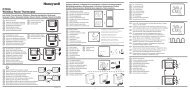
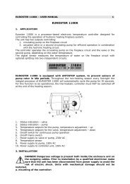
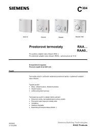
34 Application on industrial kilnsController <strong>ATR620</strong> has a wide range of applications on industrialkilns, environmental chambers, furnaces, dryers…Certainly some of the most common application fields areelectrical kilns for ceramics, glass, metalworking. Below someexamples with a short list of main configuration parameters.35 Kiln with single thermocouple and SSR controlThis is probably the most typical application of controller <strong>ATR620</strong>,using only main capabilities of the unit and still keeping high userfriendliness..On electrical kilns <strong>ATR620</strong> performs control loop for theprogrammed cycle reading thermocouple value and controllingSSR. In case that alarm conditions, as overshooting of max.temperature, are noticed relay A1 is activated to open the circuitwith safety contactor, along with acoustic signal of internal buzzerand a flashing signal on display. Should the kiln door accidentallyopen, this is also an alarm condition: cycle is stopped and acorresponding message is visualized on display.Programming of main parameters:P-01 0009 15 cycles available, 20 steps eachSpecial functions are desabledP-02 1000 Select thermocouple K (ex.:1100 for TC typeS)P-05 5000 Select SSR control output for process 1P-06 0 Minimum temperature (lower limit scale) 0°CP-07 1350 Max. temperature (upper limit scale) 1350°CP-12 1101 Max. temperature alarm with cycle blockP-15 1300 Alarm setpoint: if kiln temperature is over 1300°C,the cycle is stopped.P-17 5100 Alarm on digital input for cycle block and signal“Open door”94
CD 3000SInputLoad673-30Vdc8CD 3000SInputLoad673-30Vdc8A1- A2+A1-A2+CD 3000SInputLoad673-30Vdc8A1- A2+OUTA1A2PIXSYSPR GMS STOPTARTOKTHREE-PHASE SUPPLYL1 L2 L3Main SwitchSUPPLY230VacN FJUMPER Selection supply 230VacSafety Contactor230 VacFUSESSRModel : 2200.00.004L1ONS\CH.BCALT1V 440 A 45L2T2ONS\CH.BCALV440 A 45L3T3ONS\CH.BCALV440 A 45THERMOCOUPLEControllerModel : <strong>ATR620</strong>-21ABCO UT A 1A 2PIXSYSSTARTSTOPPRGMOKSTARDELTAHEATING ELEMENTSMicro-SwitchingOPEN DOORAN-0017-350495
36 Kiln with 2 thermocouples and contactor controlOn bigger kilns it may be necessary to introduce more precise andaccurate control of internal temperature, for example in high kilnsheat may concentrate on the highest part, leading to a relevantgap of temperature between bottom and top levels. Correctplacement of heating elements and a double control loop canachieve uniform temperature for optimal firing cycle.In this configuration two outputs of <strong>ATR620</strong> are configured ascontrol of two processes (corresponding to TC1 and TC2), thethird is available for alarm/auxiliary/event.Programming of main parameters:P-01 0009 15 cycles available, 20 steps eachSpecial functions are desabledP-02 1000 Select thermocouple K on input AN1, process 1P-03 1001 Select thermocouple K on input AN2, process 2P-05 1300 Select control output process 1 - 2 on OUT and A1P-06 0 Minimum temperature (lower limit scale) 0°CP-07 1350 Max. temperature (upper limit scale) 1350°CP-13 0000 Available for alarm / auxiliary / eventP-17 5100 Alarm on digital input for cycle block and signal“Open door”P-52 004- Max. gap process 1/process 2 : 20°C,Above this value cycle is stopped until temperatureis uniform .96
OUTA1 A 2PIXSYSPRGMSTARTSTOPOKSUPPLY230VacN FContactor Zone “A”Supply 230 VacContactor Zone “B”Supply 230 VacJUMPER Selection Supply 230VacControllerModel : <strong>ATR620</strong>-22ABCTHERMOCOUPLEZone “A”O UT A 1A 2PIXSYSPRGMSTARTSTOPOKRESISTORSZone “A”RESISTORSZone “B”THERMOCOUPLEZone “B”Micro SwitchingOPEN DOOR97
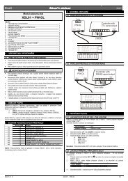
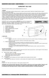
37 Kiln with 4 thermocouples - 4 units <strong>ATR620</strong>Configuration Master/SlaveConfiguration Master/Slave is suitable also for plants requiringmore than two control loops. Still it is necessary to program onesingle unit, simplifying programming and operating.The following example describes a kiln with four control loops. Upto 16 units can be connected if Waiting function is active tomonitor and compensate temperature gap among different zones,or up to 32 units if this is not required. Digital input capabilities arenot available in this configuration because serial communication isactivated.Programming of main parameters (values for Master in brackets):P-01 0000 Remote setpoint active only on Slaves(0009) Last digit set to 9 for MasterSpecial functions desabledP-02 1000 Select thermocouple K on input AN1, process 1P-05 1001 Control output for process 1 on OUT,(1000) Remote setpoint by serial input only for slavesP-06 0 Minimum temperature (lower limit scale) 0°CP-07 1350 Max. temperature (upper limit scale) 1350°CP- 0000 Digital inputs desabled17/18P-21 (120) Max. waiting time at step end: 120 minutesP-22 (20) Max. gap setpoint/process and between processesAbove this value cycle stops until temperaturereturns to limitsP-49 2010 Baudrate, format, communication delayP-50 1…3( 0)Slave address 1 to 3Enter address 0 for Master98
O A1 A2U TPIXSYSO A1 A2U TPIXSYSOUTA1A2PIXSYSST ARTSTOPOKPR GMSTA RTSTOPPRG M OKS TARTSTOPPR GMOKSTA RTSTOPPRG M OKController MASTERMod. : <strong>ATR620</strong>-21ABCController SLAVE 1Mod. : <strong>ATR620</strong>-21ABCController SLAVE 2Mod. : <strong>ATR620</strong>-21ABCController SLAVE 3Mod. : <strong>ATR620</strong>-21ABCserial Line RS 485OUA AT1 2PIXSYSSTARTSTOPO UT A 1A 2PIXSYSO UT A 1A 2PIXSYSOU A AT1 2PIXSYSPRGMOKSTARTSTOPSTARTSTOPSTARTSTOPPRGMOKPRGMOKPRGMOKContactorThermocoupleContactorThermocoupleContactorThermocoupleContactorThermocoupleResistorsZONE “A”Resistors Resistors ResistorsZONE “B” ZONE “C” ZONE “D”ZONE “A”ZONE “B”O A1 A2U TPIXSYSAN-0019-350499
38 Configuration tableDate:Installer:Notes:Model <strong>ATR620</strong>:Plant:P-01 General configurationP-02 Analog input AN1P-03 Analog input AN2P-04 ReservedP-05 Control output and source of setpointP-06 Lower limit setpoint 1 (-999/3000 digit)P-07 Upper limit setpoint 1 (-999/3000 digit)P-08 Lower limit range AN2 for V/mA(-999/3000digit)P-09 Lower limit range AN2 for V/mA (-999/3000digit)P-10 Alarms hysteresis (-999/3000)P-11 Configuration alarm no.1 (OUT)P-12 Configuration alarm no.2 (A1)P-13 Configuration alarm no.3 (A2)P-14 Setpoint alarm no.1(-999/3000 digit)P-15 Setpoint alarm no.2(-999/3000 digit)P-16 Setpoint alarm no.3(-999/3000 digit)P-17 Configuration digital input IN1P-18 Configuration digital input IN2P-19 Configuration Autotuning,step visualizationP-20 Power heating elements (0.0/999.9 KWatt)P-21 Waiting for step end (1/1440 min)P-22 Max gap at step end (1/200 digit)P-23 Cycle recoveryP-24 ReservedP-25 Filter analog inputs (1/20 medie)P-26 Offset calibration AN1 (-15.0/15.0 digit)P-27 Gain calibration AN1(-10.0%…+10.0%)P-28 End ON/OFF control (-999/3000digit)P-29 Reserved100
P-30 Max. time for impulse zone 1 (1/120sec)P-31 Limit of control signal zone 1 (10/100%)P-32 ReservedP-33 ReservedP-34 ReservedP-35 ON/OFF hysteresis;PID dead band (-99.9/300.0digit)P-36 Proportional band (0-3000digit)P-37 Integral time (0/9999 sec).P-38 Derivative time (0.0/999.9 sec).P-39 Lower limit scale 3 (-999/3000 digit)P-40 Upper limit scale 3 (-999/3000 digit)P-41 Offset AN2 (-15.0/15.0 digit)P-42 Gain AN2(-10.0%…+10.0%)P-43 Max. time for impulse zone 2 (1/120sec)P-44 Limit of control signal zone 2 (10/100%)P-45 ON/OFF hysteresis;PID dead band (-99.9/300.0digit)P-46 Proportional band (0-3000digit)P-47 Integral time (0/9999 sec).P-48 Derivative time (0.0/999.9 sec).P-49 Configuration serial inputP-50 Slave address (1/99).P-51 Visualization in RUN/START modeP-52 Programming block, endless step101
102
103
PIXSYSVia Tagliamento, 1830030 Mellaredo di Pianiga (VE)www.pixsys.nete-mail: sales@pixsys.net - support@pixsys.netSoftware Rev. 1.102300.10.025-RevC 061004*2300.10.025-C*104
105