CX606 / CX607 POWER FEED FOR MILL/DRILL - Busy Bee Tools
CX606 / CX607 POWER FEED FOR MILL/DRILL - Busy Bee Tools
CX606 / CX607 POWER FEED FOR MILL/DRILL - Busy Bee Tools
You also want an ePaper? Increase the reach of your titles
YUMPU automatically turns print PDFs into web optimized ePapers that Google loves.
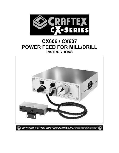
<strong>CX606</strong> / <strong>CX607</strong><br />
<strong>POWER</strong> <strong>FEED</strong> <strong>FOR</strong> <strong>MILL</strong>/<strong>DRILL</strong><br />
INSTRUCTIONS
<strong>CX606</strong> / <strong>CX607</strong><br />
SPECIFICATIONS<br />
Motor ................................ 30W, 90VDC<br />
Amp .................................. 0.6Amp<br />
Power Supply ................... 110, 15A, 60Hz<br />
Table Travel Speed Range..0 - 15-3/4"/min<br />
CONTROLS<br />
The <strong>CX606</strong>/<strong>CX607</strong> is designed to be<br />
installed on the left side of the CX600 and<br />
CX601 table respectively.<br />
E. <strong>FOR</strong>WARD/REVERSE SWITCH<br />
controls the direction of table<br />
movement. When in "0" it disengages<br />
the feed.<br />
F. LEADSCREW CONNECTOR<br />
connects the power feed to the table<br />
leadscrew.<br />
The figure below shows the controls of your<br />
power feeder.<br />
Figure-2 Limit switch and stops<br />
G. LIMIT STOPS are positioned along<br />
side the table to limit the range of<br />
table's movement.<br />
Figure-1 Feeder controls<br />
A. ON/OFF SWITCH turns the power ON<br />
or OFF to the power feeder.<br />
H. LIMIT SWITCH when activated by the<br />
limit stops. It cuts power to the power<br />
feeder. To reset, position the direction<br />
switch to neutral (middle). Disengage<br />
the power feed using the shift knob.<br />
Use the hand wheel and return the<br />
table to the operating range.<br />
B. RAPID MOVEMENT SWITCH moves<br />
the work table at maximum/minimum<br />
speed in the selected direction.<br />
C. SHIFT KNOB engages to use the<br />
power feed and disengages to use the<br />
hand wheel.<br />
D. VARIABLE SPEED KNOB controls<br />
the speed of the table movement.<br />
2
INSTALLATION<br />
Please read and understand the<br />
instructions given in this manual to install<br />
your power feeder. Read the entire<br />
installation section before you begin<br />
installation.<br />
While the end plate is off the table and<br />
before installing the power feeder, insert the<br />
two T-nuts into the front slot of the table for<br />
mounting the table stops in the later step.<br />
Remove the cap screws and remove the<br />
bottom cover shown in figure-5.<br />
TO INSTALL THE <strong>POWER</strong> <strong>FEED</strong>:<br />
Remove the nut securing the hand wheel<br />
and remove the hand wheel from the left<br />
side of the table. See figure-3.<br />
Figure-5 Bottom cover removed<br />
Replace the key in the leadscrew, align the<br />
keyway on the power feeder and install the<br />
power feeder to the table.<br />
Figure-3 Hand wheel removed<br />
Remove the key from the lead screw. See<br />
figure-4.<br />
Remove the cap screws securing the table<br />
end plate and remove the end plate. See<br />
figure-4.<br />
Figure-6 Installing the power feed<br />
Secure the power feed to the table from<br />
underneath using cap screws provided. See<br />
figure-7.<br />
Figure-4 Removing cap screws and end<br />
plate<br />
3
Figure-7 Securing the power feed to the<br />
table<br />
Replace the bottom cover using the screws<br />
that were removed in the previous step.<br />
Remove the center stop block by removing<br />
the two cap screws securing it to the table.<br />
See figure-8.<br />
Figure-9 Bracket mounting holes location<br />
Use a 3.3mm /30 drill bit and drill two holes<br />
for mounting the limit switch. Once the<br />
holes are drilled, tap the holes with a M4-.7<br />
tap drill.<br />
Attach the limit switch to the table and<br />
secure it using two cap screws provided.<br />
See figure-10.<br />
Figure-8 Removing center stop block and<br />
table lock levers<br />
Remove the nut on the cross feed hand<br />
wheel and remove the hand wheel.<br />
Figure-10 Installing the limit switch<br />
Remove the two round table stops using a<br />
proper sized hex wrench. See figure-11.<br />
Hold the bracket with the limit switch<br />
against the table and mark the table with a<br />
marker through the holes on the bracket.<br />
Remove the bracket with the limit switch<br />
and use a hammer and a center punch and<br />
mark the hole locations for drilling.<br />
Figure-11 Removing the round table stops<br />
4
Attach the limit stops to the table slot by<br />
securing the cap screws to the T-slot nuts<br />
along the table. See figure-12.<br />
Use a proper sized screw driver and<br />
remove the motor brush cap from the motor<br />
housing. See figure-14.<br />
Figure-12 Installing the table limit stops<br />
Re-install the table lock levers.<br />
Re-install the cross feed hand wheel.<br />
MOTOR BRUSH<br />
REPLACEMENT<br />
The power feeder is powered by a DC<br />
motor that has brushes which will need to<br />
be replaced periodically as they need.<br />
Figure-14 Motor brush<br />
Remove the used motor brush and replace<br />
it with a new one.<br />
Replace the second motor brush in the<br />
same manner.<br />
Reinstall the motor brush cover.<br />
Reinstall the power feed side cover.<br />
TO REPLACE THE MOTOR BRUSH:<br />
Remove the four cap screws on the side of<br />
the power feed and remove the side cover<br />
to access the motor and the motor brushes.<br />
See figure-13.<br />
Figure-13 Removing the side cover<br />
5
WARRANTY<br />
CRAFTEX LIMITED 3 YEARS WARRANTY<br />
Craftex warrants every product to be free from defects in materials and agrees to correct such defects where<br />
applicable. This warranty covers three years for parts and 90 days for labour (unless specified otherwise), to the<br />
original purchaser from the date of purchase but does not apply to malfunctions arising directly or indirectly from<br />
misuse, abuse, improper installation or assembly, negligence, accidents, repairs or alterations or lack of<br />
maintenance.<br />
Proof of purchase is necessary.<br />
All warranty claims are subject to inspection of such products or part thereof and Craftex reserves the right to<br />
inspect any returned item before a refund or replacement may be issued.<br />
This warranty shall not apply to consumable products such as blades, bits, belts, cutters, chisels, punches<br />
etceteras.<br />
Craftex shall in no event be liable for injuries, accidental or otherwise, death to persons or damage to property or<br />
for incidental contingent, special or consequential damages arising from the use of our products.<br />
RETURNS, REPAIRS AND REPLACEMENTS<br />
To return, repair, or replace a Craftex product, you must visit the appropriate <strong>Busy</strong> <strong>Bee</strong> <strong>Tools</strong> showroom or call 1-<br />
800-461-BUSY. Craftex is a brand of equipment that is exclusive to <strong>Busy</strong> <strong>Bee</strong> <strong>Tools</strong>.<br />
For replacement parts directly from <strong>Busy</strong> <strong>Bee</strong> <strong>Tools</strong>, for this machine, please call 1-800-461-BUSY (2879), and<br />
have your credit card and part number handy.<br />
<br />
<br />
<br />
<br />
<br />
<br />
<br />
<br />
<br />
<br />
<br />
<br />
All returned merchandise will be subject to a minimum charge of 15% for re-stocking and handling with the<br />
following qualifications.<br />
Returns must be pre-authorized by us in writing.<br />
We do not accept collect shipments.<br />
Items returned for warranty purposes must be insured and shipped pre-paid to the nearest warehouse<br />
Returns must be accompanied with a copy of your original invoice as proof of purchase. Returns must be in<br />
an un-used condition and shipped in their original packaging a letter explaining your reason for the return.<br />
Incurred shipping and handling charges are not refundable.<br />
<strong>Busy</strong> <strong>Bee</strong> will repair or replace the item at our discretion and subject to our inspection.<br />
Repaired or replaced items will be returned to you pre-paid by our choice of carriers.<br />
<strong>Busy</strong> <strong>Bee</strong> reserves the right to refuse reimbursement or repairs or replacement if a third party without our<br />
prior authorization has carried out repairs to the item.<br />
Repairs made by <strong>Busy</strong> <strong>Bee</strong> are warranted for 30 days on parts and labour.<br />
Any unforeseen repair charges will be reported to you for acceptance prior to making the repairs.<br />
The <strong>Busy</strong> <strong>Bee</strong> Parts & Service Departments are fully equipped to do repairs on all products purchased from us<br />
with the exception of some products that require the return to their authorized repair depots. A <strong>Busy</strong> <strong>Bee</strong><br />
representative will provide you with the necessary information to have this done.<br />
For faster service it is advisable to contact the nearest <strong>Busy</strong> <strong>Bee</strong> location for parts availability prior to<br />
bringing your product in for repairs.<br />
8


