V9648-V1_31-01- Prospekt - Martens Elektronik GmbH
V9648-V1_31-01- Prospekt - Martens Elektronik GmbH
V9648-V1_31-01- Prospekt - Martens Elektronik GmbH

Create successful ePaper yourself
Turn your PDF publications into a flip-book with our unique Google optimized e-Paper software.
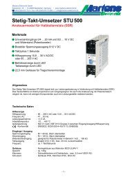
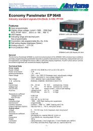
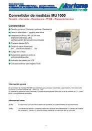
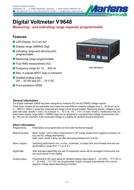
Digital Voltmeter V 9648<br />
Measuring - and indicating range separate programmable<br />
Features<br />
M LED-Display 14.2 mm red<br />
M Display range ±9999(0) Digit<br />
M Indicating range and decimal point<br />
programmable<br />
M Measuring range programmable<br />
M True RMS measurement (AC)<br />
M Frequency range AC 15 ... 400 Hz<br />
M Max. 4 outputs SPDT relay or transistor<br />
M Isolated analog output<br />
0/4 ... 20 mA and 0/2 ... 10 V DC<br />
M Front protection IP655<br />
DIN 96x48mm<br />
General information<br />
The Digital Voltmeter <strong>V9648</strong> has been designed to measure DC and AC(TRMS) voltage signals.<br />
Three basic models all are selectable and makes the possibility to measure voltages from 0... 30.00 mV up to<br />
0 ... 999.9 V. Within a model the measurement range is free programmable. Measuring bipolar voltages is possible<br />
with basic models 1 and 2, for example -5 ... +5 V; or -10 ... +10 V in basic model 2. Additional a free programmable<br />
display range within ± 9999(0) digit can be assigned to a programmed voltage measurement range.<br />
This can be important, if the measured voltage is a degree for another physical dimension.<br />
Short information<br />
Programming Parameters are programmed via front-side membrane keypad.<br />
Measuring input<br />
Alarm outputs<br />
Digital filter<br />
Analog output<br />
Baisc model 1 and 2 offers measurement ± DC (range always from negative to positive value)<br />
and AC voltage alternatively.<br />
Note: basic model 3 doos not offer decoupling between AC and DC.<br />
Switching performance min. or max., hysteresis, on-delay time and off-delay time are programmable<br />
in range from 1 s up to 9 h.<br />
With activated digital filter the last 16 measured values will be averaged continuously and<br />
the result shown in the display.<br />
Proportional to the input signal an isolated analog output signal 0 ... 20 mA/0 ... 10 V DC or<br />
4 ... 20 mA/2 ... 10 V DC can be generated. Output changed automatically from current<br />
signal to voltage signal depending on burden.<br />
- 1 -
Technical data<br />
Power supply<br />
Supply voltage : 230 V AC ±10 %; 115 V AC ±10 %, 24 V AC ±10 % or 24 V DC ±15 %<br />
Power consumption : max. 3.5 VA, with analog output 5 VA<br />
Operating temperature : -10 ... +55 °C<br />
Rated voltage<br />
: Model 1 + 2; 300 V AC acc. VDE <strong>01</strong>10 between input/output/supply voltage<br />
Model 3; 1000 V between input/output, supply voltage<br />
Degree of pollution 2,<br />
Over-voltage category : Model 1 + 2, category III<br />
Model 3, < 600 V category III, > 600 V category II<br />
Test voltage : Model 1 + 2; 4 kV DC between input/output/supply voltage<br />
Model 3, 6 kV between input/output, supply voltage<br />
- conformity : EN55022, EN60555, IEC61000-4-3/4/5/11/13<br />
Input<br />
Input resistance<br />
Overload<br />
Accuracy<br />
Temperature coefficient<br />
Display<br />
Display range<br />
Parameter display<br />
Output<br />
Relay<br />
Transistor<br />
Analog output<br />
-Accuracy<br />
Case<br />
Dimensions<br />
Weight<br />
Electrical connection<br />
Protection<br />
: Model 1 = 130 kOhm, Model 2 = 1.3 MOhm, Model 3 = 2.6 MOhm<br />
: Model 1+2 = 300 V AC/DC; Model 3 = 1200 V AC/DC<br />
: < 0.1 % ±2 digit (DC); 0.5 % ±2 digit (AC)<br />
: 0.05 %/K<br />
: LED red, 14.2 mm<br />
: ±9999(0) digit , leading zero suppression<br />
: LED 2-digit red, 7 mm (parameter - and output indicator)<br />
: SPDT < 250 V AC < 250 VA < 2 A, < 300 V DC < 50 W < 2 A<br />
: max. 35 V AC/DC/100 mA, short circuit protected<br />
: 0/4 ... 20 mA burden ≤500 Ω; 0/2 ... 10 V burden >500 Ω, isolated<br />
Automatic output changing (burden dependent)<br />
: 0.1 %; TK 0.<strong>01</strong> %/K<br />
: Panel case DIN 96x48 mm, material PA6-GF; UL94V-0<br />
: Front 96x48 mm, mounting depth 100 mm,<br />
: max. 390 g<br />
: Clamp terminals, 2 mm² single wire, 1,5 mm² flexible wire, AWG14<br />
: Front IP65, terminals IP20, fingersafe acc. German BGV A3<br />
Dimensions<br />
Seal<br />
Position terminal strips<br />
Panel cut-out<br />
acc. to DIN 43700-96x48<br />
- 2 -
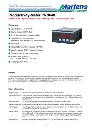
Connection diagrams<br />
Terminal strip A<br />
Input 0 ... 30 mV/1000 V AC/DC<br />
Terminal strip B (varies with version)<br />
2 alarm outputs<br />
Relay Transistor<br />
Terminal strip C (varies with version)<br />
2 alarm outputs Analog output<br />
Relay Transistor AO<br />
Terminal strip D supply voltage (varies with version)<br />
- 3 -
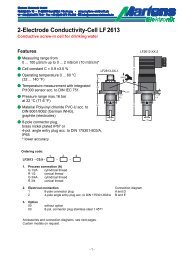
Controls and indicators<br />
Fixed zero<br />
Field for<br />
additional text<br />
Actual value<br />
Parameter display<br />
or activated<br />
alarm outputs<br />
. For se-<br />
Field for unit<br />
Parameter button<br />
Down button<br />
Up button<br />
Description<br />
Operating of the device is arranged in 2 levels. The requested parameter can be called by button<br />
lections within a parameter or for entering data, use buttons and .<br />
After power-on, the device initializes itself. The display shows the message .<br />
After the initializing procedure the device is located in the Working level. Set points of the alarm outputs can<br />
be programmed if they are available.<br />
Pressing the button for more than 2 seconds, activates the Configuration level. Now all the parameters<br />
which defines the function of the panelmeter can be programmed. E.g. the switching performance of the alarm<br />
outputs and the analog output.<br />
After finishing the configuration or when no button was pushed for more than 2 minutes, the program returns to<br />
the working level. Leaving the configuration level is possible at any time by pressing the button for more<br />
than 2 seconds.<br />
Parameter display as status indicator for the alarm outputs A1-A4.<br />
Segments f (A1/A3) and/or b (A2/A4) are flashing with 2 Hz, if the delay time is active.<br />
Segments e (A1/A3) or c (A2/A4) are output indicators.<br />
Error codes:<br />
Display flashes<br />
<br />
The input signal is situated around more than 3 % outside of the programmed measuring<br />
range. The A/D- converter is over driving and the display flashes with appr. 1 Hz.<br />
EEPROM test. Reading this message, an error has been occurred. When pushing the button<br />
a copy of the EEPROM will be reloaded. The device works with the factory settings.<br />
Is this copy not working, please ship the panelmeter to factory for repair service.<br />
Parameter locked. See configuration page 7.<br />
Start-up note: The device has to be configured, before it can be used ⇒ see page 6.<br />
- 4 -
Notes to representation<br />
Parameter is only displayed when configurated<br />
Parameter is only displayed when feature is included (see order code)<br />
Please Note: All parameters can be called if they are not blocked by other programmed parameters and if<br />
they are available. Factory settings are shown in the display.<br />
Working level<br />
Button Display Description<br />
Actual value<br />
<br />
<br />
Output indication<br />
(only if installed and activated).<br />
<br />
<br />
Display brightness<br />
Permanent changing in the working level possible.<br />
Setting possible in 9 steps with buttons and .<br />
Note : only model 1 and 2.<br />
<br />
<br />
Max. peak reading<br />
Reset with buttons or , and at every power off.<br />
<br />
<br />
Min. peak reading<br />
Reset with buttons or , and at every power off.<br />
<br />
<br />
Setpoint output A1<br />
Setting possible from ... with buttons and .<br />
(start value) ... (end value)<br />
Note:<br />
Setpoints for alarm outputs A1 ... A4 have to be configured in the same way.<br />
- 5 -
Configuration<br />
Button Display Description (Display graphic shows factory settings)<br />
Press<br />
2 s<br />
1<br />
<br />
<br />
Digital filter<br />
, Averaging of the last 16 measured values continously.<br />
Selection with buttons and .<br />
2<br />
<br />
<br />
Display correction<br />
Setting possible from () ... () Digit<br />
with buttons and .<br />
3<br />
<br />
<br />
Input signal<br />
DC voltage unipolar (measuring range 0 ... end value , Param. 4)<br />
DC voltage bipolar (measuring range e.g. -100 ... +100V)<br />
AC voltage TRMS<br />
Selection with buttons and .<br />
4<br />
<br />
<br />
Measuring range (End value)<br />
Model 1 30.00 ... 4000 mV (floating point)<br />
Model 2 3.000 ... 250.0 V (floating point)<br />
Model 3 200.0 ... 999.9 V<br />
Selection with buttons and .<br />
5<br />
<br />
<br />
Fixed zero 0, e.g +<br />
; <br />
Selection with buttons and .<br />
6<br />
<br />
7<br />
<br />
<br />
<br />
Decimal places<br />
if = : . . . .<br />
if = : . . . .<br />
Selection with buttons and .<br />
Start value for indicating range and analog output.<br />
Setting possible from ... digit with buttons and .<br />
In case of modification a new configuration of the alarm outputs is necessary.<br />
8<br />
<br />
<br />
End value for indicating range and analog output.<br />
Setting from ... digit with buttons and .<br />
In case of modification a new configuration of the alarm outputs is necessary.<br />
If > , the output works with a decreasing characteristic.<br />
continue page 7<br />
- 6 -
Button Display Description (Display graphic shows factory settings)<br />
9<br />
Switching function alarm output A1<br />
, (min) , (max)<br />
<br />
If activated the start value will be loaded for set point.<br />
Selection with buttons and .<br />
10<br />
<br />
<br />
Setpoint alarm output A1<br />
Setting possible from (start value) ... (end value)<br />
with buttons and .<br />
11<br />
<br />
<br />
Hysteresis alarm output A1<br />
Setting possible from ... () Digit<br />
with buttons and .<br />
12<br />
<br />
<br />
Switch-on delay time alarm output A1<br />
Setting possible from .. ... .. (h.mm.ss)<br />
with buttons and .<br />
13<br />
14<br />
<br />
<br />
<br />
15<br />
<br />
<br />
<br />
Switch-off delay time alarm output A1<br />
Setting possible from .. ... .. (h.mm.ss)<br />
with buttons and .<br />
Note:<br />
The parameter settings for A2 ... A4 have to be configured in the same way.<br />
Analog output<br />
mA (0 - 10 V DC)<br />
mA (2 - 10 V DC)<br />
The switch-over from current to voltage output is load dependent<br />
(≤ 500 Ω = current output, > 500 Ω = voltage output).<br />
Selection with buttons and .<br />
Code for factory settings<br />
16<br />
<br />
<br />
Programming lock<br />
: no lock<br />
: configuration level locked<br />
: all parameters locked<br />
Selection with buttons and .<br />
<br />
<br />
Return to the working level<br />
- 7 -
Ordering code<br />
<strong>V9648</strong> -<br />
1.<br />
-<br />
2.<br />
-<br />
3.<br />
-<br />
4.<br />
-<br />
5.<br />
-<br />
6.<br />
-<br />
7.<br />
1. Terminal strip A<br />
Display range and decimal place free programmable from:<br />
1<br />
2<br />
0 ... 30.00 mV<br />
0 ... 3.000 V<br />
to<br />
to<br />
0 ... 4000m V*<br />
0 ... 250.0 V*<br />
DC/ACTRMS<br />
DC/ACTRMS<br />
*(includes e.g. ±5 V, ±10 V )<br />
3 0(5) ... 200.0 V to 0(5) ... 999.9 V DC/ACTRMS<br />
2. Terminal strip B<br />
00 not installed<br />
2R 2 alarm outputs<br />
2T 2 alarm outputs<br />
3. Terminal strip C<br />
00 not installed<br />
2R 2 alarm outputs<br />
2T 2 alarm outputs<br />
AO Analog output<br />
relay SPDT<br />
transistor<br />
relay SPDT<br />
transistor<br />
0/4 ... 20 mA or 0/2 ... 10 V DC<br />
isolated<br />
4. Terminal strip D supply voltage<br />
0 230 V AC ± 10 % 50-60 Hz<br />
1 115 V AC ± 10 % 50-60 Hz<br />
4 24 V AC ± 10 % 50-60 Hz<br />
5 24 V DC ± 15 %<br />
5. Option<br />
00<br />
<strong>01</strong><br />
07<br />
without option<br />
min- and max-peak-hold<br />
display brightness programmable, only model 1 and 2<br />
6. Unit (appears in the unit field)<br />
7. Additional text (will be placed in the field for<br />
additional text, max. 3x90 mm HxW)<br />
- 8 -<br />
<strong>01</strong>/03-<strong>V1</strong>.<strong>31</strong>-<strong>01</strong>