Remote Alarms Manual.pdf - Air Systems International
Remote Alarms Manual.pdf - Air Systems International
Remote Alarms Manual.pdf - Air Systems International

Create successful ePaper yourself
Turn your PDF publications into a flip-book with our unique Google optimized e-Paper software.
Models<br />
50-ALM, 50-ALMST, 50-ALMAA,<br />
50-ALMSTAA, 50ALMSTHAA,<br />
50-ALMSTH & 50-ALM-2J<br />
AUDIO/VISUAL REMOTE ALARMS<br />
<strong>Manual</strong> No. ALRM001<br />
(Rev 7 April 2005)<br />
Operating <strong>Manual</strong><br />
Appa<br />
AIR SYSTEMS INTERNATIONAL, INC.<br />
829 Juniper Crescent, Chesapeake, Va. , 23320<br />
Telephone (757) 424-3967<br />
Toll Free 1-800-866-8100<br />
Fax No. (757) 424-5348<br />
http://www.airsystems.com<br />
e-mail: sales@airsystems.com<br />
<strong>Air</strong> <strong>Systems</strong> <strong>International</strong>, Inc.<br />
Registered to ISO 9001<br />
Certificate No. A5033<br />
Printed in U.S.A<br />
©Copyright <strong>Air</strong> <strong>Systems</strong> <strong>International</strong>, Inc. 2005. All Rights Reserved.
OVERVIEW<br />
-2-<br />
These alarm units have been designed to provide a remote alarm capability for many of <strong>Air</strong><br />
<strong>Systems</strong>' products. Their function is to duplicate local alarms found on the primary equipment<br />
and to signal workers in a remote location that there is an alarm condition with their system.<br />
They act as a valuable early warning device for the isolated worker and allows him to make a safe<br />
egress from a hazardous work environment. Virtually all of our equipment can be outfitted with a<br />
remote alarm device.<br />
SPECIFICATIONS<br />
Power Required:<br />
Weight:<br />
ELECTRIC MODELS ONLY<br />
8 -12 Volts DC<br />
2 - 4 lbs<br />
Cable:<br />
Connector:<br />
50 ft. standard (other lengths are<br />
available as an option)<br />
4 position twist lock<br />
SETUP PROCEDURE<br />
PNEUMATIC MODEL 50-ALMP<br />
Pressure: 15 -125psi inlet pressure<br />
Horn Set Pressure: 15psi<br />
Weight:<br />
2 lbs<br />
Connector: 1/8" plug (snaps into socket on<br />
primary device)<br />
1.) Test batteries and replace if necessary. (Models 50-ALMST and 50-ALMSTH only).<br />
2.) Attach connector on the end of the remote alarm cable or hose to the mating connector<br />
found on the primary device. Note: Primary device refers to the product you will be<br />
connecting the remote alarm to.
-3-<br />
OPERATION<br />
FOR MODELS 50-ALM, 50-ALMH, 50-ALMST,<br />
50-ALMSTH, 50-ST<br />
1.) If the remote alarm is connected to a device that monitors for CO (carbon monoxide),<br />
locate the on/off/test switch on the right endplate of the CO monitor. Hold the switch in<br />
the test position and check the remote alarm, the audible alarm should be pulsing and the<br />
strobe (if installed) should be flashing.<br />
2.) Release the switch to the on position. The unit is now operational.<br />
1A.)<br />
If the remote alarm is connected to a device that signals a loss of pressure, locate the low<br />
pressure alarm on/off switch and flip it to the on position. The audible alarm should be<br />
pulsing and the strobe (if installed) should be flashing. Note: Pressure must be below<br />
500psi on high pressure units or below 50psi on low pressure units for the alarms to<br />
activate.<br />
The unit is now operational.<br />
OPERATION<br />
FOR MODELS 50-ALMAA & 50-ALMSTAA<br />
1.) These remote alarms should be used with “Auto-<strong>Air</strong>” devices. Locate the on/off/test<br />
switch located on the right endplate of the CO monitor. Hold the switch in the test position<br />
and check the remote alarm. One audible alarm should be producing a constant tone.<br />
Release the on/off/test switch and located the backup air alarm on/off switch on the left<br />
endplate of the monitor. Flip the switch to the on position and check the remote alarm.<br />
One alarm should be pulsing and the strobe (if installed) should be flashing. Note:<br />
Primary air must be disconnected from the “Auto-<strong>Air</strong>” device or be below 50psi for the<br />
backup alarms to activate.<br />
The unit is now operational.<br />
OPERATION<br />
FOR MODEL 50-ALMP<br />
1.) Turn the regulator knob in the remote alarm box fully counterclockwise.<br />
2.) Pressurize the primary device.<br />
3.) Set primary device in alarm mode. This could be high CO, backup air, or low pressure.<br />
4.) Turn regulator knob in remote alarm box clockwise until horn reaches desired sound level<br />
(15psi is usually sufficient).<br />
5.) Reset the primary device to normal operation. The unit is now operational.
PROBLEM<br />
<strong>Remote</strong> alarm doesn't sound<br />
but primary alarm operates.<br />
-4-<br />
TROUBLESHOOTING<br />
SOLUTION<br />
Check alarm cable jack to see if it is secured<br />
tightly to remote alarm jack.<br />
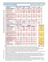
SETUP/OPERATION FOR MODEL 50-ALM-2J<br />
The 50-ALM-2J remote alarm interface box is designed to accommodate two remote alarms<br />
with a single input signal. It requires two 9-volt batteries to operate.<br />
1.) Install two (2) 9-volt batteries in the battery pack compartment. Make sure the positive (+)<br />
and negative (-) terminals of the batteries are installed properly. Polarity markings are<br />
located in the battery drawers (note that they are installed in the inverted position).<br />
Periodically replace the two 9-volt batteries located inside the interface box.<br />
2.) Attach the supplied jumper wire to the remote alarm jack located on the Breather Box.<br />
3.) Attach the other end of the supplied jumper wire to the 50- ALM-2J box on the incoming<br />
connection (see attached drawing).<br />
4.) Attach the remote alarms to the remote alarm output jacks.<br />
Check to see if fresh batteries are in<br />
both the primary unit and remote alarm<br />
device (Models 50-ALMST and 50-ALMSTH).<br />
Check to see if wires are properly<br />
connected to audible and visual alarms.<br />
Bottled air units must have low<br />
pressure, usually below 600 psi, to make<br />
the alarm activate. On/off switch must be<br />
"on".<br />
CO monitor "test" switch must be lifted up to<br />
operate alarm.<br />
5.) Test the remote alarms by placing the carbon monoxide test on/off switch to the test<br />
position.<br />
6.) The alarms will sound.<br />
TROUBLESHOOTING<br />
1.) If the unit is not functioning at all or has a weak output signal, replace 9-volt batteries.<br />
2.) If a particular jack is not functioning, remove the box cover and check for a broken wire or<br />
unsoldered connection. See proper wiring schematic attached.
-5-<br />
MODEL<br />
50-ALM-2J
-6-<br />
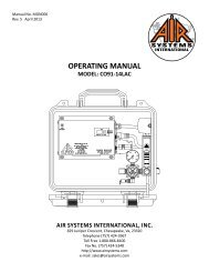
REPLACEMENT ITEMS<br />
MODEL 50-ALM<br />
ITEM # DESCRIPTION PART #<br />
1 AUDIBLE ALARM ELLS004<br />
2 4 POSITION PLUG ELJP003<br />
3 18-2 SJ CABLE ELCB006
-7-<br />
REPLACEMENT ITEMS<br />
MODEL 50-ALMAA<br />
ITEM # DESCRIPTION PART #<br />
1 AUDIBLE ALARM ELLS004<br />
2 4 POSITION PLUG ELJP003<br />
3 22-4 CABLE ELCB018
-8-<br />
REPLACEMENT ITEMS<br />
MODEL 50-ALMH<br />
ITEM # DESCRIPTION PART #<br />
1 HIGH INTENSITY ALARM ELLS003<br />
2 4 POSITION PLUG ELJP003<br />
3 18-2 SJ CABLE ELCB006
-9-<br />
REPLACEMENT ITEMS<br />
MODEL 50-ALMSTAA<br />
Note: Light<br />
activates on<br />
reserve air mode<br />
only<br />
HIGH CO<br />
ALARM<br />
ITEM # DESCRIPTION PART #<br />
1 AUDIBLE ALARM ELLS004<br />
2 4 POSITION PLUG ELJP003<br />
3 22-4 CABLE ELCB018<br />
4 STROBE GUARD ELDS011<br />
5 STROBE ELDS007<br />
6 BULB FOR STROBE ELDS010<br />
7 RED LENS FOR STROBE ELDS010L<br />
RESERVE AIR ACTIVATION<br />
ALARM
-10-<br />
REPLACEMENT ITEMS<br />
MODEL 50-ST<br />
ITEM # DESCRIPTION PART #<br />
1 4 POSITION PLUG ELJP003<br />
2 18-2 SJ CABLE ELCB006<br />
3 STROBE GUARD ELDS011<br />
4 STROBE ELDS007<br />
5 BULB FOR STROBE ELDS010<br />
6 RED LENS FOR STROBE ELDS010L
-11-<br />
REPLACEMENT ITEMS<br />
MODEL 50-ALMP<br />
ITEM # DESCRIPTION PART #<br />
1 PNEUMATIC HORN GAMLHORN<br />
2 PRESSURE GAUGE GA1515B<br />
3 INLET PLUG QDCSL2M<br />
4 PRESSURE REGULATOR WL013<br />
5 BRAIDED HOSE HOS004
-12-<br />
REPLACEMENT ITEMS<br />
MODEL 50-ALMST<br />
ITEM # DESCRIPTION PART #<br />
1 AUDIBLE ALARM ELLS004<br />
2 4 POSITION PLUG ELJP003<br />
3 TWIN 9V BATTERY HOLDER MONC006<br />
4 18-2 SJ CABLE ELCB006<br />
5 STROBE GUARD ELDS011<br />
6 STROBE ELDS007<br />
7 BULB FOR STROBE ELDS010<br />
8 RED LENS FOR STROBE ELDS010L
-13-<br />
REPLACEMENT ITEMS<br />
MODEL 50-ALMSTH<br />
ITEM # DESCRIPTION PART #<br />
1 HIGH INTENSITY ALARM ELLS003<br />
2 4 POSITION PLUG ELJP003<br />
3 TWIN 9V BATTERY PACK MONC006<br />
4 18-2 SJ CABLE ELCB006<br />
5 STROBE GUARD ELDS011<br />
6 STROBE ELDS007<br />
7 BULB FOR STROBE ELDS010<br />
8 RED LENS FOR STROBE ELDS010L
ITEM # DESCRIPTION PART #<br />
1 HIGH INTENSITY ALARM ELLS003<br />
2 4 POSITION PLUG ELJP003<br />
3 22-4 CABLE ELCB018<br />
4 STROBE GUARD ELDS011<br />
5 STROBE ELDS007<br />
6 BULB FOR STROBE ELDS010<br />
7 RED LENS FOR STROBE ELDS010L<br />
REPLACEMENT ITEMS<br />
MODEL 50ALMSTHAA
Warranty Disclaimer<br />
<strong>Air</strong> <strong>Systems</strong>’ manufactured equipment is warranted to the original user against defects in workmanship<br />
or materials under normal use for one year after date of purchase. Any part which is determined<br />
by <strong>Air</strong> <strong>Systems</strong> to be defective in material or workmanship will be, as the exclusive remedy,<br />
repaired or replaced at <strong>Air</strong> <strong>Systems</strong>’ option. This warranty does not apply to electrical systems or<br />
electronic components. Electrical parts are warranted, to the original user, for 90 days from the<br />
date of sale. During the warranty period, electrical components will be repaired or replaced at <strong>Air</strong><br />
<strong>Systems</strong>’ option.<br />
NO OTHER WARRANTY, EXPRESSED OR IMPLIED, AS TO DESCRIPTION, QUAL-<br />
ITY, MERCHANTABILITY, FITNESS FOR A PARTICULAR PURPOSE, OR ANY<br />
OTHER MATTER IS GIVEN BY AIR SYSTEMS IN CONNECTION HEREWITH. UN-<br />
DER NO CIRCUMSTANCES SHALL THE SELLER BE LIABLE FOR LOSS OF<br />
PROFITS, ANY OTHER DIRECT OR INDIRECT COSTS, EXPENSES, LOSSES OR<br />
DAMAGES ARISING OUT OF DEFECTS IN, OR FAILURE OF THE PRODUCT OR<br />
ANY PART THEREOF.<br />
The purchaser shall be solely responsible for compliance with all applicable Federal, State and<br />
Local OSHA and/or MSHA requirements. Although <strong>Air</strong> <strong>Systems</strong> <strong>International</strong> believes that its<br />
products, if operated and maintained as shipped from the factory and in accordance with our “operations<br />
manual”, conform to OSHA and/or MSHA requirements, there are no implied or expressed<br />
warranties of such compliance extending beyond the limited warranty described herein. Product<br />
designs and specifications are subject to change without notice. Rev 2 12/98<br />
<strong>Air</strong> leaks are not covered under warranty except when they result from a defective system<br />
component, i.e. an on/off valve or regulator or upon initial delivery due to poor workmanship.<br />
<strong>Air</strong> leaks due to poor delivery or damage will be covered under delivery claims. Minor<br />
air leaks are part of routine service and maintenance and are the responsibility of the customer<br />
just as are filters and oil changes.