Altivar 71 - error
Altivar 71 - error
Altivar 71 - error

You also want an ePaper? Increase the reach of your titles
YUMPU automatically turns print PDFs into web optimized ePapers that Google loves.
<strong>Altivar</strong> <strong>71</strong><br />
User's manual<br />
Retain for future use<br />
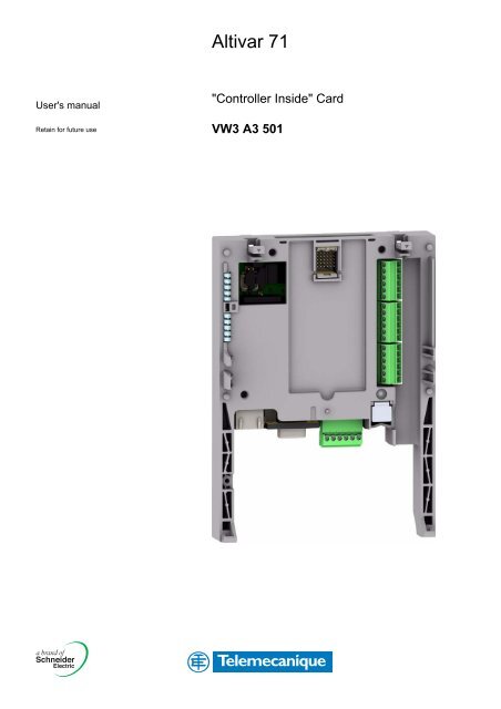
"Controller Inside" Card<br />
VW3 A3 501
Sommaire<br />
Before you begin_____________________________________________________________________________________________ 4<br />
Documentation structure_______________________________________________________________________________________ 5<br />
Introduction_________________________________________________________________________________________________ 6<br />
Presentation _____________________________________________________________________________________________ 6<br />
Description ______________________________________________________________________________________________ 6<br />
Dialog __________________________________________________________________________________________________ 7<br />
Master CANopen communication_____________________________________________________________________________ 7<br />
Communication with a PLC _________________________________________________________________________________ 7<br />
Clock___________________________________________________________________________________________________ 8<br />
Programming ____________________________________________________________________________________________ 8<br />
Hardware setup _____________________________________________________________________________________________ 9<br />
Receipt _________________________________________________________________________________________________ 9<br />
Installing the card in the drive________________________________________________________________________________ 9<br />
Description of terminals ___________________________________________________________________________________ 10<br />
Characteristics __________________________________________________________________________________________ 11<br />
Schemes_______________________________________________________________________________________________ 12<br />
Connection to a CANopen bus ______________________________________________________________________________ 13<br />
Example of connection to a CANopen bus_____________________________________________________________________ 14<br />
Connecting the "Controller Inside" card to a PC_________________________________________________________________ 15<br />
Data backup battery ______________________________________________________________________________________ 16<br />
Configuration ______________________________________________________________________________________________ 17<br />
Configuring the switches___________________________________________________________________________________ 17<br />
Diagnostics ________________________________________________________________________________________________ 18<br />
LEDs__________________________________________________________________________________________________ 18<br />
I/O monitoring ___________________________________________________________________________________________ 19<br />
Card fault ______________________________________________________________________________________________ 20<br />
Operation using the graphic display terminal ______________________________________________________________________ 21<br />
Factory-loaded program ___________________________________________________________________________________ 21<br />
Example of a special program ______________________________________________________________________________ 23<br />
Operation using the integrated display terminal ____________________________________________________________________ 24<br />
Factory-loaded program ___________________________________________________________________________________ 24<br />
Special program _________________________________________________________________________________________ 24<br />
While every precaution has been taken in the preparation of this document,<br />
Schneider Electric SA assumes no liability for any omissions or <strong>error</strong>s it may contain,<br />
nor for any damages resulting from the application or use of the information herein.<br />
The products and options described in this document may be changed or modified at<br />
any time, either from a technical point of view or in the way they are operated.<br />
Their description can in no way be considered contractual.<br />
3
Before you begin<br />
Read and understand these instructions before performing any procedure on this drive.<br />
HAZARDOUS VOLTAGE<br />
DANGER<br />
• Read and understand the Installation manual before installing or operating the <strong>Altivar</strong> <strong>71</strong> drive. Installation,<br />
adjustment, repair, and maintenance must be performed by qualified personnel.<br />
• The user is responsible for compliance with all international and national electrical standards in force concerning<br />
protective grounding of all equipment.<br />
• Many parts of this variable speed drive, including the printed circuit boards, operate at the line voltage.<br />
DO NOT TOUCH.<br />
Use only electrically insulated tools.<br />
• DO NOT touch unshielded components or terminal strip screw connections with voltage present.<br />
• DO NOT short across terminals PA and PC or across the DC bus capacitors.<br />
• Install and close all the covers before applying power or starting and stopping the drive.<br />
• Before servicing the variable speed drive<br />
- Disconnect all power<br />
- Place a “DO NOT TURN ON” label on the variable speed drive disconnect<br />
- Lock the disconnect in the open position<br />
• Disconnect all power including external control power that may be present before servicing the drive.<br />
WAIT 15 MINUTES to allow the DC bus capacitors to discharge. Then follow the DC bus voltage measurement<br />
procedure given in the installation manual to verify that the DC voltage is less than 45 VDC. The drive LEDs are not<br />
accurate indicators of the absence of DC bus voltage.<br />
Electric shock will result in death or serious injury.<br />
CAUTION<br />
DAMAGED EQUIPMENT<br />
Do not install or operate any drive that appears damaged.<br />
Failure to follow this instruction can result in equipment damage.<br />
4
Documentation structure<br />
Installation manual<br />
This manual describes:<br />
• Assembly<br />
• How to connect the drive<br />
Programming manual<br />
This manual describes:<br />
• The functions<br />
• The parameters<br />
• How to use the drive display terminal (integrated display terminal and graphic display terminal)<br />
Communication parameters manual<br />
This manual describes:<br />
• The drive parameters with specific information (addresses, formats, etc) for use via a bus or communication network<br />
• The operating modes specific to communication (state chart)<br />
• The interaction between communication and local control<br />
Modbus, CANopen, Ethernet, Profibus, INTERBUS, Uni-Telway, DeviceNet, Modbus Plus and FIPIO<br />
manuals<br />
These manuals describe:<br />
• Connection to the bus or network<br />
• Configuration of the communication-specific parameters via the integrated display terminal or the graphic display terminal<br />
• Diagnostics<br />
• Software setup<br />
• The communication services specific to the protocol<br />
<strong>Altivar</strong> 58/58F compatibility manual<br />
This manual describes the differences between the <strong>Altivar</strong> <strong>71</strong> and the <strong>Altivar</strong> 58/58F.<br />
It explains how to replace an <strong>Altivar</strong> 58 or 58F, including how to replace drives communicating on a bus or network.<br />
5
Introduction<br />
Presentation<br />
The “Controller Inside” programmable card is used to adapt the variable speed drive to specific applications by integrating control system<br />
functions.<br />
Various predefined configurable applications are sold by Telemecanique and its partners.<br />
The PS 1131 software workshop for PC is used for programming and debugging new applications, quickly and in an open-ended manner.<br />
It is not possible to transfer the program from the card to the PC, which enables us to protect our know-how.<br />
Only one “Controller Inside” programmable card can be installed in the <strong>Altivar</strong> <strong>71</strong> drive. It can be combined with another option card<br />
(I/O extension or communication). Consult the tables summarizing the possible combinations: drives, options and accessories,<br />
see catalogue.<br />
The “Controller Inside” programmable card has:<br />
• 10 logic inputs, 2 of which can be used for 2 counters or 4 of which can be used for 2 incremental encoders<br />
• 2 analog inputs<br />
• 6 logic outputs<br />
• 2 analog outputs<br />
• A master port for the CANopen bus<br />
• A PC port for programming with the PS 1131 software workshop<br />
• If the power consumption table does not exceed 200 mA, this card can be powered by the drive. Otherwise, an external 24 V c power<br />
supply must be used.<br />
The “Controller Inside” programmable card can also use:<br />
• The drive I/O<br />
• The I/O extension card I/O<br />
• The encoder interface card points counter<br />
• The drive parameters (speed, current, torque, etc)<br />
Description<br />
5 6<br />
1 RJ45 connector for connecting the PS 1131 software workshop via an RS 485 serial link.<br />
Connection to the PC is via a cable and an RS 232/RS 485 converter included in the<br />
PowerSuite for PC connection kit, VW3 A8 106.<br />
4<br />
2 9-way male SUB-D connector for connection to the CANopen bus.<br />
3 Connector with removable screw terminals, 6 contacts at intervals of 3.81 for the<br />
24 V c power supply and 4 logic inputs.<br />
4 3 connectors with removable screw terminals, 6 contacts at intervals of 3.81 for 6 logic<br />
inputs, 6 logic outputs, 2 analog inputs, 2 analog outputs and 2 commons.<br />
1 2 3<br />
5 5 LEDs, comprising:<br />
• 1 to indicate the presence of the 24 V c power supply<br />
• 1 to indicate a program execution fault<br />
• 2 to indicate the CANopen bus communication status<br />
• 1 controlled by the application program<br />
6 Block of 4 configuration switches<br />
6
Introduction<br />
Dialog<br />
ATV <strong>71</strong><br />
Modbus bus<br />
XBT Magelis<br />
Human-machine dialog with the application programmed in the “Controller Inside”<br />
programmable card is possible using:<br />
• The <strong>Altivar</strong> <strong>71</strong> graphic display terminal<br />
• A Magelis industrial HMI terminal connected to the drive Modbus port<br />
• A Magelis industrial HMI terminal connected to the Ethernet TCP/IP network (if the drive is<br />
equipped with an Ethernet TCP/IP communication card)<br />
One graphic terminal menu is dedicated to the “Controller Inside” programmable card. This<br />
menu can be customized by the card program according to the application.<br />
Sensors<br />
Independent machine with multiwire system<br />
Any industrial HMI terminal which supports the Modbus protocol can be used to display and<br />
modify the “Controller Inside” programmable card parameters. The card Modbus server<br />
provides access to 2048 Kwords (% MW, etc).<br />
Master CANopen communication<br />
ATV <strong>71</strong><br />
XBT Magelis<br />
The master CANopen port on the “Controller Inside” programmable card can be<br />
used to extend the I/O capacity (using CANopen I/O modules) and to control other<br />
CANopen slave devices.<br />
Modbus bus<br />
CANopen bus<br />
ATV 31 ATV 31 Advantys STB<br />
distributed I/O<br />
FTB 1CN<br />
Independent machine with CANopen bus<br />
Communication with a PLC<br />
Premium<br />
ATV <strong>71</strong><br />
Ethernet TCP/IP network<br />
ATV <strong>71</strong><br />
XBT Magelis<br />
The <strong>Altivar</strong> <strong>71</strong> drive equipped with a “Controller Inside” programmable card fits easily<br />
into complex architectures.<br />
Regardless of which bus or network is being used (Ethernet TCP/IP, Modbus/<br />
Uni-Telway, FIPIO, Modbus Plus, Profibus DP, InterBus, etc), the PLC can<br />
communicate with the “Controller Inside” programmable card and the drive. The periodic<br />
variables can still be configured as required.<br />
CANopen bus<br />
Sensors ATV 31 FTB 1CN<br />
Modular machine with Ethernet TCP/IP network<br />
7
Introduction<br />
Clock<br />
A clock backed up by a lithium battery makes it possible to have a log of events that have occurred. When the “Controller Inside”<br />
programmable card is installed in the drive, the drive faults are automatically time and date-stamped without special programming.<br />
Programming<br />
In factory settings mode, the "Controller Inside" card only contains the clock function.<br />
For other applications, the program must be loaded:<br />
• By loading an existing program (procedure described in the PS 1131documentation)<br />
• Or by loading a custom-built program, with the aid of the PS 1131 software workshop, using the function libraries dedicated to<br />
programming the "Controller Inside" card.<br />
In order to program the "Controller Inside" card, it is necessary to undergo training.<br />
The PS1131 CD-Rom contains:<br />
• This manual, already available on the CD-Rom supplied with each <strong>Altivar</strong> <strong>71</strong><br />
• The PS 1131 software workshop<br />
• The online help<br />
• The standard function library<br />
• Program examples<br />
• The <strong>Altivar</strong> <strong>71</strong> parameters manual<br />
The standard function library contains:<br />
• Logic functions (AND, OR, etc)<br />
• Mathematical functions (Cos, Sin, Exp, etc)<br />
• Functions dedicated to drives which simplify data exchanges between the drive and the "Controller Inside" programmable card (example:<br />
sending the speed reference)<br />
• Functions for managing the CANopen bus<br />
• Graphic terminal display functions<br />
This manual does not describe programming using PS 1131.<br />
Note: PS 1131 is also called CoDeSys.<br />
CoDeSys V2.2 can be used on the Controller Inside for <strong>Altivar</strong> 58 (VW3A581131), but must not be used for programming the Controller<br />
Inside for <strong>Altivar</strong> <strong>71</strong> (VW3 A3 501).<br />
8
Hardware setup<br />
Receipt<br />
• Check that the card catalog number marked on the label is the same as that on the delivery note corresponding to the purchase order.<br />
• Remove the option card from its packaging and check that it has not been damaged in transit.<br />
• Check that the product is complete: the packaging should contain the "Controller Inside" option card and its 4 removable terminals.<br />
Installing the card in the drive<br />
See the <strong>Altivar</strong> <strong>71</strong> Installation Manual.<br />
Note: If a Controller Inside card and an I/O extension card are installed simultaneously:<br />
• The I/O extension card must be installed on the drive first<br />
• Then the Controller Inside card must be installed on the I/O extension card<br />
9
Hardware setup<br />
Description of terminals<br />
AO52<br />
COM<br />
A051<br />
AI52<br />
COM<br />
AI51<br />
LO56<br />
LO55<br />
LO54<br />
LO53<br />
LO52<br />
LO51<br />
LI60<br />
LI59<br />
LI58<br />
LI57<br />
LI56<br />
LI55<br />
24V<br />
COM<br />
LI51<br />
LI52<br />
LI53<br />
LI54<br />
Terminal<br />
24V<br />
COM<br />
Function<br />
Power supply for the "Controller Inside" card, logic outputs and analog outputs.<br />
If allowed by the power consumption table (for example if outputs are not being used), the "Controller Inside" card can<br />
be powered by the 24 V c power supply in the drive.<br />
If you are using an external power supply:<br />
• The "Controller Inside" card should preferably be turned on before the drive. However, the "Controller Inside" card<br />
must without fail be turned on no more than 2s after the drive is turned on.<br />
Failure to follow this instruction locks the drive in card fault mode (ILF). This fault cannot be reset, and the only way to<br />
acknowledge it is to turn off the drive.<br />
• Catalog number for a Telemecanique power supply (24 V c, 2A): ABL7 RE 24 02.<br />
Common ground and electrical 0V of the "Controller Inside" card power supply, logic inputs, (LIpp), outputs (LOpp),<br />
analog inputs (AIpp) and analog outputs (AOpp).<br />
This ground and electrical 0V are common with the drive ground and electrical 0V. There is therefore no point in<br />
connecting this terminal to the 0V terminal on the drive control terminals.<br />
LI51 to LI60 24 V c logic inputs<br />
Inputs LI51, LI52, LI59 and LI60 can be configured for the use of 2 counter inputs or 2 incremental encoder inputs:<br />
Counter 1 input: LI51<br />
Incremental encoder 1 inputs: channel A = LI51, channel B = LI52<br />
Counter 2 input: LI59<br />
Incremental encoder 2 inputs: channel A = LI59, channel B = LI60<br />
LO51 to LO56 24 V c logic outputs<br />
AI51 and AI52 0 ... 20mA analog inputs<br />
AO51 and AO52 0 ... 20mA analog outputs<br />
10
Hardware setup<br />
Characteristics<br />
Electrical characteristics<br />
Power Voltage V 24 c (min. 19, max. 30)<br />
Current consumption Maximum A 2<br />
No-load mA 80<br />
Using logic output mA 200 maximum (1)<br />
Analog inputs AI51, AI52 2 current analog inputs 0…20 mA, impedance 250 Ω<br />
Resolution: 10 bits<br />
Accuracy: ± 1% for a temperature variation of 60°C<br />
Linearity: ± 0.2% of the maximum value<br />
Common point for all the card I/O (2)<br />
Analog outputs AO51, AO52 2 current analog outputs 0…20 mA, impedance 500 Ω<br />
Resolution: 10 bits<br />
Accuracy: ± 1% for a temperature variation of 60°C<br />
Linearity: ± 0.2% of the maximum value<br />
Common point for all the card I/O (2)<br />
Logic inputs LI51…LI60 10 logic inputs, 2 of which can be used for 2 counters or 4 of which can<br />
be used for 2 incremental encoders<br />
Impedance 4.4 kΩ<br />
Maximum voltage: 30 V c<br />
Switching thresholds:<br />
State 0 if y 5 V or logic input not wired<br />
State 1 if u 11 V<br />
Common point for all the card I/O (2)<br />
Logic outputs LO51…LO56 Six 24 V c logic outputs, positive logic open collector type (source),<br />
compatible with level 1 PLC, standard IEC 65A-68<br />
Maximum switching voltage: 30 V<br />
Maximum current: 200 mA<br />
Common point for all the card I/O (2)<br />
I/O connection Type of contact Screw, at intervals of 3.81 mm 2<br />
Maximum wire mm 2 1.5 (AWG 16)<br />
Tightening torque Nm 0.25<br />
Lithium battery Life 8 years approx.<br />
Characteristics of the application program<br />
Compiled program<br />
Maximum size Kb 320<br />
(saved in “flash” memory)<br />
Data Maximum size Kword 64<br />
Saved size (NVRAM) Kword 4<br />
Size accessible by Kword 2<br />
Modbus<br />
Characteristics of the CANopen communication port<br />
Structure Connector One 9-way male SUB-D connector<br />
Network management Master<br />
Transmission speed Configurable via the program:<br />
50 kbps, 125 kbps, 250 kbps, 500 kbps or 1 Mbps<br />
Address (Node ID) 32 slaves maximum<br />
Services<br />
CANopen application DS 301 V4.02<br />
layer<br />
Channel config. DSP 405<br />
PDO<br />
9 receive and transmit PDOs in total for each slave<br />
SDO<br />
2 client SDOs per slave (1 read and 1 write). Block transfer<br />
Error check<br />
Node Guarding, producer and consumer Heartbeat<br />
Other services Emergency, Boot-up, Sync<br />
Configuration<br />
The CANopen network configurator is integrated in the PS1131 software<br />
workshop.<br />
Diagnostics Using LEDs 2 LEDs: “RUN” and “ ERROR”, conforming to CIA DR303 version 1.0<br />
(1) If the power consumption table does not exceed 200 mA, this card can be powered by the drive. Otherwise, an external 24 V c power supply must be used.<br />
(2) This common point is also the drive 0 V (COM).<br />
11
Hardware setup<br />
Schemes<br />
Card powered by the drive<br />
Only if the power consumption is less than 200 mA; otherwise use an external power supply.<br />
ATV <strong>71</strong>Hppppp<br />
VW3 A3 501<br />
SW1<br />
Source<br />
Sink<br />
Ext. Int.<br />
+ 24 V<br />
LI5p<br />
LO5p<br />
LO5p<br />
24 V<br />
AI51<br />
AI52<br />
COM<br />
0-20 mA 0-20 mA<br />
Card powered by external power supply<br />
VW3 A3 501<br />
COM<br />
LI5p<br />
LO5p<br />
LO5p<br />
24 V<br />
AI51<br />
AI52<br />
COM<br />
AO51<br />
AO52<br />
COM<br />
+ 24 V<br />
0 V<br />
24 V c supply<br />
0-20 mA 0-20 mA<br />
0-20 mA 0-20 mA<br />
12
Hardware setup<br />
Connection to a CANopen bus<br />
Pinout for the CANopen 9-way SUB-D connector<br />
1 5<br />
9 6<br />
Terminal Description<br />
1 not connected<br />
2 CAN_L<br />
3 CAN_GND<br />
4 not connected<br />
5 not connected<br />
6 CAN_GND<br />
7 CAN_H<br />
8 not connected<br />
9 not connected<br />
Use a straight connector (catalog number TSX CAN KCDF 180T) to connect the "Controller Inside" card to the CANopen bus.<br />
This connector integrates a line terminator that must be activated if the "Controller Inside" card is at one end of the CANopen bus.<br />
It is not possible to use an angled connector because of the terminals located to the right of the CANopen connector.<br />
The 9-way SUB-D connector on the "Controller Inside" card is linked to the card ground and the drive ground. The shielding must be<br />
connected to the connector ground.<br />
The CANopen signals on the "Controller Inside" card are isolated.<br />
Speed and length of the CANopen bus<br />
It is essential to make sure that all devices connected to the CANopen bus operate at the same transmission speed.<br />
The CANopen transmission speed of the "Controller Inside" card is configured from the PS 1131 software workshop.<br />
The maximum length of the CANopen bus depends on the transmission speed on this bus.<br />
The table below indicates the maximum lengths permitted according to the transmission speed:<br />
Transmission speed 50 kbps 125 kbps 250 kbps 500 kbps 1 Mbps<br />
Max. length of bus 1000m 500m 200m 100m 5m<br />
13
Hardware setup<br />
Example of connection to a CANopen bus<br />
Description<br />
<strong>Altivar</strong> <strong>71</strong> drive<br />
equipped with a "Controller Inside" card<br />
CANopen connector<br />
9-way female SUB-D connector with line terminator (can be deactivated)<br />
2 CANopen cables can be connected<br />
180° cable outlet<br />
CAN-H, CAN-L, CAN-GND connection<br />
LSZH CANopen cable<br />
CE certified CANopen cable. Low smoke emission, non halogen and flame retardant<br />
(IEC 60332-1).<br />
UL/IEC332-2 CANopen cable<br />
UL certified CANopen cable. Flame retardant (IEC 60332-2).<br />
LSZH HD flexible CANopen cable<br />
CANopen cable for intensive use and moving applications. Flame retardant<br />
(IEC 60332-1). Non halogen. Oil resistant.<br />
Junction box for CANopen bus<br />
2 RJ45 connectors for connecting 2 drop cables<br />
VW3 CAN CA RRpp<br />
1 RJ45 connector for connecting the PowerSuite software workshop<br />
Two 5-pin screw terminals for connecting 2 CANopen cables (CAN_H, CAN_L,<br />
CAN_GND, CAN_V+, CAN_SHLD)<br />
Line terminator (can be deactivated)<br />
Reference<br />
number<br />
Length<br />
m<br />
Catalog number<br />
1 - ATV<strong>71</strong>pppp<br />
VW3 A3 501<br />
2 - TSX CAN KCDF 180T<br />
3 50 TSX CAN CA 50<br />
100 TSX CAN CA 100<br />
300 TSX CAN CA 300<br />
3 50 TSX CAN CB 50<br />
100 TSX CAN CB 100<br />
300 TSX CAN CB 300<br />
3 50 TSX CAN CD 50<br />
100 TSX CAN CD 100<br />
300 TSX CAN CD 300<br />
4 - VW3 CAN TAP 2<br />
Drop cable for CANopen bus<br />
5 0.3 VW3 CAN CA RR03<br />
Equipped with 2 RJ45 connectors<br />
1 VW3 CAN CA RR10<br />
<strong>Altivar</strong> 31 drive 6 - ATV31ppp<br />
CANopen Advantys OTB I/O modules<br />
Power supply 24 V c, 12 inputs 24 V c, 2 outputs 24 V c 0.3A<br />
6 relay outputs 30 V c/240 V a 2 A, removable screw terminals<br />
7 - OTB1 C0 DM9LP<br />
CANopen Advantys FTB I/O module 8 - FTB 1CNppp p0<br />
M12 connector for CANopen cable<br />
5 female contacts, A coding<br />
CANopen extension cable for Advantys FTB module<br />
Equipped with 2 angled connectors: M12, 5-way, A coding<br />
CANopen line terminator for Advantys FTB module<br />
Equipped with an M12 connector<br />
9 - FTX CN12F5<br />
10 - FTX CN32pp<br />
11 FTX CNTL12<br />
14
Hardware setup<br />
Connecting the "Controller Inside" card to a PC<br />
The "Controller Inside" card RJ45 connector complies with the RS485 standard.<br />
The connection kit for PC serial port (catalog number VW3 A8 106) can be used to connect a PC to<br />
the "Controller Inside" card.<br />
This kit contains a cable equipped with 2 RJ45 connectors, as well as an RS485/RS232 converter.<br />
As the RS485/RS232 converter is powered by the "Controller Inside" card, no external power supply<br />
is required.<br />
Characteristics of the programming port<br />
The RJ45 connector is shielded and connected to the ground on the "Controller Inside" card, which is itself connected to the drive ground.<br />
View from<br />
8.......................1<br />
Terminal<br />
Description<br />
1 not connected<br />
2 not connected<br />
3 not connected<br />
4 B signal (RS485) = V1 signal (Modbus)<br />
5 A signal (RS485) = V0 signal (Modbus)<br />
6 not connected<br />
7 Modbus VP signal<br />
12 V DC power supply supplied by the "Controller Inside" card (only for the power supply of a<br />
RS485/RS232 converter)<br />
8 Modbus common signal<br />
0V<br />
15
Hardware setup<br />
Data backup battery<br />
The "Controller Inside" card has a non-volatile RAM (NVRAM) which is needed to store variables. A lithium battery is mounted on this nonvolatile<br />
RAM to avoid this data being lost when the card is turned off.<br />
When installing the "Controller Inside" card in the drive, make sure that this battery<br />
is present. It takes the form of a rectangular block clipped onto the non-volatile RAM<br />
(see schematic opposite).<br />
The battery life is approximately 8 years when turned off.<br />
The battery has a realtime clock for timestamping faults.<br />
The date and time on this clock are checked and set from a special sub-menu in the<br />
[1.14 - PROG. CARD MENU] customizable menu in the graphic display<br />
terminal.<br />
The date and time need to be set on receipt of the "Controller Inside" card, or after<br />
replacing its lithium battery.<br />
Lithium<br />
battery<br />
The lithium battery must only be replaced when the drive and the "Controller Inside"<br />
card are turned off.<br />
During this operation, the data saved in the NVRAM (4 Kwords) are lost.<br />
16
Configuration<br />
Configuring the switches<br />
The "Controller Inside" card has a block of 4 switches as illustrated below.<br />
These switches can only be set when the drive and the "Controller Inside" card are turned off, since it is<br />
necessary to remove the drive control front panel in order to access it.<br />
By default, all the switches are in the Off position.<br />
Write protection switch<br />
The right-hand switch (switch 4) is used to protect the PS 1131 program in the Flash memory.<br />
Switches<br />
Description<br />
A new program cannot be transferred.<br />
A new program can be transferred.<br />
Programmable switches<br />
The three left-hand switches (switches 1 to 3) can be used by the "Controller Inside" card program, depending on the application.<br />
Switches Value Switches Value Switches Value Switches Value<br />
0 1 2 3<br />
4 5 6 7<br />
17
Diagnostics<br />
LEDs<br />
1.1 CANopen RUN<br />
The "Controller Inside" card is equipped with five LEDs<br />
which can be seen through the window in the <strong>Altivar</strong> <strong>71</strong><br />
cover.<br />
1.2 CANopen ERROR<br />
1.3 Power<br />
1.4 Application<br />
1.5 Watchdog<br />
LED Color State Meaning<br />
1.1 CANopen RUN green<br />
1.2 CANopen ERROR red<br />
off<br />
flashing<br />
on<br />
off<br />
1 flash per second<br />
2 flashes per second<br />
on<br />
CANopen master in STOPPED state<br />
CANopen master in PRE-OPERATIONAL state<br />
CANopen master in OPERATIONAL state<br />
No CANopen <strong>error</strong><br />
The CANopen master <strong>error</strong> counter has reached or exceeded its warning level<br />
(too many <strong>error</strong>s)<br />
Node Guarding <strong>error</strong> (vis-à-vis a CANopen slave) or Heartbeat <strong>error</strong> (CANopen<br />
master acting as consumer)<br />
The CANopen master is in the "OFF" state.<br />
1.3 Power green<br />
off<br />
"Controller Inside" card not supplied with power<br />
on<br />
"Controller Inside" card supplied with power (24 V c present)<br />
1.4 Application yellow The meaning of this LED is determined by the "Controller Inside" card program.<br />
1.5 Watchdog red on<br />
The "Controller Inside" card program has generated an <strong>error</strong> and has been<br />
stopped (watchdog tripped).<br />
18
Diagnostics<br />
I/O monitoring<br />
The values of all the "Controller Inside" card logic and analog I/O can be displayed on the graphic display terminal: [1.2 - MONITORING]<br />
menu, [ PROG. CARD I/O MAP] sub-menu.<br />
RUN Term +50.00Hz 80A Move from one screen to another<br />
PROG. CARD I/O MAP<br />
(from PROG CARD LI MAP<br />
PROG CARD LI MAP<br />
to PROG. CARD AO MAP)<br />
PROG CARD AI MAP<br />
PROG CARD LO MAP<br />
by turning the navigation button<br />
PROG. CARD AO MAP<br />
Code<br />
Quick<br />
state 0<br />
state 1<br />
RUN Term +50.00Hz 80A<br />
PROG CARD LI MAP<br />
LI51 LI52 LI53 LI54 LI55 LI56 LI57 LI58<br />
1<br />
0<br />
LI59 LI60<br />
1<br />
0<br />
> Quick<br />
RUN Term +50.00Hz 80A RUN Term +50.00Hz 80A<br />
PROG CARD AI MAP AI51<br />
ENT<br />
AI51 : 0.000 mA<br />
AI52 : 9.87 V<br />
0 mA<br />
Min = 0.001 Max = 20,000<br />
Code > Quick > Quick<br />
state 0<br />
state 1<br />
RUN Term +50.00Hz 80A<br />
PROG CARD LO MAP<br />
1<br />
0<br />
LO51 LO52 LO53 LO54 LO55 LO56<br />
> Quick<br />
RUN Term +50.00Hz 80A RUN Term +50.00Hz 80A<br />
PROG. CARD AO MAP AO51<br />
ENT<br />
AO51 : 0.000 mA<br />
AO52 : 9.87 V<br />
0 mA<br />
Min = 0.001 Max = 20,000<br />
Code > Quick > Quick<br />
Note: The addresses of the parameters mentioned above are given in the "Communication parameters manual".<br />
19
Diagnostics<br />
Card fault<br />
The [internal com. link] (ILF) fault appears when serious problems arise:<br />
- Hardware fault in the Controller Inside card<br />
- Dialog fault between the Controller Inside card and the drive<br />
The drive behavior cannot be configured when an [internal com. link] (ILF) fault occurs, and the drive trips with freewheel stopping. This<br />
fault cannot be reset.<br />
Two diagnostic parameters can be used to obtain more detailed information on the origin of the [internal com. link] (ILF) fault:<br />
- [Internal link fault 1] (ILF1) if the fault has occurred on option card no. 1 (installed directly on the drive).<br />
- [Internal link fault 2] (ILF2) if the fault has occurred on option card no. 2 (installed directly on the drive).<br />
The Controller Inside card can be in position 1 or in position 2.<br />
Parameters [Internal link fault 1] (ILF1) and [Internal link fault 2] (ILF2) can only be accessed on the graphic display terminal, in the [1.10<br />
DIAGNOSTICS] (DGT-), [MORE FAULT INFO] (AFI-) menu.<br />
Value Description of the values of the [Internal link fault 1] (ILF1) and [Internal link fault 2] (ILF2) parameters<br />
0 No fault<br />
1 Loss of internal communication with the drive<br />
2 Hardware fault detected<br />
3 Error in the EEPROM checksum<br />
4 Faulty EEPROM<br />
5 Faulty Flash memory<br />
6 Faulty RAM memory<br />
7 Faulty NVRAM memory<br />
8 Faulty analog input<br />
9 Faulty analog output<br />
10 Faulty logic input<br />
11 Faulty logic output<br />
101 Unknown card<br />
102 Exchange problem on the drive internal bus<br />
103 Time out on the drive internal bus (500 ms)<br />
20
Operation using the graphic display terminal<br />
Factory-loaded program<br />
Controller Inside menu<br />
RDY Term +0.00Hz 0A<br />
MAIN MENU<br />
1 DRIVE MENU<br />
2 ACCESS LEVEL<br />
3 OPEN / SAVE AS<br />
4 PASSWORD<br />
5 LANGUAGE<br />
Code<br />
Quick<br />
ENT<br />
RDY Term +0.00Hz 0A<br />
1 DRIVE MENU<br />
1.1 SIMPLY START<br />
1.2 MONITORING<br />
1.3 SETTINGS<br />
1.4 MOTOR CONTROL<br />
1.5 INPUTS/OUTPUTS CFG<br />
Code > Quick<br />
1.6 COMMAND<br />
1.7 APPLICATION FUNCT.<br />
1.8 FAULT MANAGEMENT<br />
1.9 COMMUNICATION<br />
1.10 DIAGNOSTICS<br />
1.11 IDENTIFICATION<br />
1.12 FACTORY SETTINGS<br />
1.13 USER MENU<br />
1.14 PROGRAMMABLE CARD<br />
ENT<br />
NST CAN 0.0Hz 0.0A<br />
1.14 PROGRAMMABLE CARD<br />
Modbus add Prg C. : 17<br />
DATE/TIME SETTINGS<br />
Code > Quick<br />
Controller Inside card Modbus address<br />
The [Modbus add Prg C.] (AMOA) parameter can be set in the [1.14 PROGRAMMABLE CARD] menu.<br />
This setting can also be accessed in the [1.9 - COMMUNICATION] (COM-) menu, [MODBUS NETWORK] (Md1-) submenu.<br />
21
Operation using the graphic display terminal<br />
Setting the date and time<br />
In the [1.14 PROGRAMMABLE CARD] menu, [DATE/TIME SETTINGS] sub-menu, you can set:<br />
- the year<br />
- the month<br />
- the day<br />
- the hours<br />
- the minutes<br />
NST CAN 0.00Hz 0.0A<br />
DATE/TIME SETTINGS<br />
Hour<br />
10 : 42<br />
Minutes<br />
Month<br />
Day<br />
11 / 03 / 2005<br />
> Quick<br />
Year<br />
Note: The date and time are not refreshed on this settings screen. The current date and time [Date/Time] (CLO) can be viewed in the<br />
[1.2 MONITORING] (SUP-) menu.<br />
Note: It is not possible to change either the date or time format:<br />
• The date cannot be displayed in the "year/month/day" format.<br />
• The time cannot be displayed in the "10:42 am" format.<br />
Note: It is not possible to configure changes between winter and summer hours.<br />
22
Operation using the graphic display terminal<br />
Example of a special program<br />
The name of menu 1.14 has been customized.<br />
The application parameters are edited in plain text and arranged in menus.<br />
CYCLE IN PROGRESS<br />
Current cycle : 5<br />
Current phase : 2<br />
Operation : dosing<br />
Product : oil<br />
Duration : 30s<br />
SETTINGS<br />
Cycle selected : 10<br />
No. of phases : 6<br />
Phase selected : 2<br />
Operation sel : mixing<br />
Duration sel : 120s<br />
RUN APP +50.0Hz 2.1A<br />
1.14 DOSING<br />
CYCLE IN PROGRESS<br />
Current cycle : 5<br />
Current phase : 2<br />
Operation : dosing<br />
Product : oil<br />
Code > Quick<br />
CYCLE IN PROGRESS<br />
Current cycle : 5<br />
Current phase : 2<br />
Operation : dosing<br />
Product : oil<br />
Duration : 30s<br />
SETTINGS<br />
Cycle selected : 10<br />
No. of phases : 6<br />
Phase selected : 2<br />
Operation sel : mixing<br />
Duration sel : 120s<br />
RUN APP +50.0Hz 2.1A<br />
1.14 DOSING<br />
SETTINGS<br />
Cycle selected : 10<br />
No. of phases : 6<br />
Phase selected : 2<br />
Operation sel : mixing<br />
Code > Quick<br />
23
Operation using the integrated display terminal<br />
Factory-loaded program<br />
Controller Inside menu<br />
Power-up<br />
XXX<br />
Displays the state of the drive<br />
ENT<br />
ESC<br />
SIM-<br />
ESC<br />
USr-<br />
ESC<br />
SPL-<br />
ENT<br />
ESC<br />
PROGRAMMABLE CARD<br />
ESC<br />
COd-<br />
ESC<br />
LAC-<br />
The [Modbus add Prg C.] (AMOA) parameter can be set, as in the (COM-) menu, (Md1-) sub-menu.<br />
Note: It is not possible to set either the date or the time.<br />
Special program<br />
Controller Inside HMI words are displayed in the form (O01) to (O50).<br />
Lists are displayed in the format (EL1) to (EL20).<br />
24
atv<strong>71</strong>_Controller_Inside_EN_V1<br />
2005-04