Masterpact NT06-16 IEC - error
Masterpact NT06-16 IEC - error
Masterpact NT06-16 IEC - error
- No tags were found...

Create successful ePaper yourself
Turn your PDF publications into a flip-book with our unique Google optimized e-Paper software.
Low Voltage Products<strong>Masterpact</strong> <strong>NT06</strong>-<strong>16</strong> <strong>IEC</strong>User manual
User manual for<strong>Masterpact</strong> <strong>NT06</strong>-<strong>16</strong> <strong>IEC</strong>circuit breakersDiscovering <strong>Masterpact</strong> 2Using <strong>Masterpact</strong> 8Understanding the controls and indications 8Charging the circuit breaker 9Closing the circuit breaker 10Opening the circuit breaker 11Resetting after a fault trip 12Locking the controls 13Using the <strong>Masterpact</strong> drawout chassis <strong>16</strong>Identifying the circuit breaker positions <strong>16</strong>Racking 17Matching a <strong>Masterpact</strong> circuit breaker with its chassis 20Locking the switchboard door 21Locking the circuit breaker in position 22Locking the safety shutters 25Identifying the electrical auxiliaries 26Identification of the connection terminals 26Operation 27Electrical diagrams 28Discovering <strong>Masterpact</strong>'s accessories 30Micrologic control units 30Indication contacts 31Auxiliaries for remote operation 33Device mechanical accessories 36Chassis accessories 38Inspecting and testing before use 40Initial tests 40What to do when the circuit breaker trips 41Maintaining <strong>Masterpact</strong> performance 42Recommended maintenance program 42Maintenance operations 43Ordering replacement parts 44Troubleshooting and solutions 46Checking <strong>Masterpact</strong> operating conditions 481<strong>Masterpact</strong> <strong>NT06</strong>-<strong>16</strong> <strong>IEC</strong>
Discovering <strong>Masterpact</strong>E51299ARating plateE60055A2<strong>Masterpact</strong> <strong>NT06</strong>-<strong>16</strong> <strong>IEC</strong>Schneider Electric
3<strong>Masterpact</strong> <strong>NT06</strong>-<strong>16</strong> <strong>IEC</strong>Schneider Electric
Discovering <strong>Masterpact</strong><strong>Masterpact</strong> circuit breakers are available in drawout and fixed versions.The drawout version is mounted on a chassis and the fixed version is installedusing fixing brackets.Drawout versionE51321ARESETFixed versionE51322ARESET4<strong>Masterpact</strong> <strong>NT06</strong>-<strong>16</strong> <strong>IEC</strong>Schneider Electric
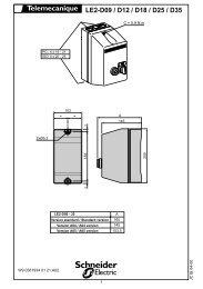
Discovering <strong>Masterpact</strong>Drawout circuit breaker / switch-disconnectorE60057AXF closing releaseMX/1 opening releaseArc chuteMX/2 opening release or MNundervoltage releaseTerminals for control unit, faultindication contacts, controlauxiliaries and auxiliary contactsSDE/1 "fault-trip" indication contactOF "ON/OFF" indication contactsPF "ready to close" contactOperating-mechanismcharging handleCarrying gripMCH gear motor forelectrical charging of theoperating mechanismKeylock for locking in open positionBPFE electrical closing pushbuttonSide plate fordrawout deviceSDE/2 "fault-trip" indication contactor Res electrical remote resetControl unitClosing pushbuttonOpening pushbuttonOperation counterBPFE electrical closing pushbuttonPadlock for lockingin open position6<strong>Masterpact</strong> <strong>NT06</strong>-<strong>16</strong> <strong>IEC</strong>Schneider Electric
Fixed circuit breaker / switch-disconnectorE60058AControl auxiliary terminalsMX/1 opening releaseArc chuteMX/2 opening release or MN undervoltagereleaseTerminals for control unit and faultindication contactsSDE/1 "fault-trip" indication contactAuxiliary contact terminalsOF "ON/OFF" indication contactsPF "ready to close" contactOperating-mechanismcharging handleCarrying gripMCH gear motor forelectrical charging of theoperating mechanismKeylock for lockingin open positionBPFE electrical closing pushbuttonBPFE electrical closing pushbuttonSide plate for fixeddevicePadlock for lockingin open positionSDE/2 "fault-trip" indication contactor Res electrical remote resetControl unitClosing pushbuttonOpening pushbuttonOperation counterFrontE60059ATrip indication button usedto reset before closingRESETRating plateLocking by padlock, lead-seal coveror screws for pushbuttonsIndicator for position of themain contacts"Springs charged" and "Readyto close" indicator7<strong>Masterpact</strong> <strong>NT06</strong>-<strong>16</strong> <strong>IEC</strong>Schneider Electric
Using <strong>Masterpact</strong>Understanding the controls andindicationsE51344AE51488ACircuit breaker open anddischargedO IPush OFFPush ONE51489ACircuit breaker closed anddischargedO IPush OFFPush ONCircuit breaker open,charged and not "readyto close"Circuit breaker closed andchargedO IPush OFFPush ONO IPush OFFPush ONCircuit breaker open,charged and "ready toclose"E51492AE51490AE51491AO IPush OFFPush ON8<strong>Masterpact</strong> <strong>NT06</strong>-<strong>16</strong> <strong>IEC</strong>Schneider Electric
Charging the circuit breakerE60072AThe charge status is indicated as follows.O IPush OFFPush ONThe springs in the circuit breaker operating mechanism must be charged to storethe energy required to close the main contacts. The springs may be chargedmanually using the charging handle or automatically by the optional MCH gearmotor.Manual charging.Pull the handle downseven times until youhear a "clack".Automatic charging.If the MCH gear motor isinstalled, the spring isautomatically rechargedafter each closing.E51347AE46790AorMERLIN GERIN9<strong>Masterpact</strong> <strong>NT06</strong>-<strong>16</strong> <strong>IEC</strong>Schneider Electric
Using <strong>Masterpact</strong>Closing the circuit breakerE51292AE51291ADevice "ready to close"Device not "ready to close"Closing conditionsClosing (i.e. turning the circuit ON) is possible only if the circuit breaker is"ready to close".The prerequisites are the following:b device open (OFF)b springs chargedb no opening order present.The circuit breaker will not close unless it is "ready to close" when the orderis given.Closing the circuit breakerLocally (mechanical)Press the mechanical ON pushbutton.E60047AE51493AOPuPush OFFLocally (electrical)E60049ABPFEE51294AXFPress the electrical closingpushbutton. By adding anXF closing release, thecircuit breaker can be closedlocally.RemotelyE60048AE51294AXFWhen connected to a remote control panel, the XFclosing release can be used to close the circuitbreaker remotely.Anti-pumping functionThe purpose of the mechanical anti-pumping function is to ensure that a circuitbreaker receiving simultaneous opening and closing orders does not open andclose indefinitely.If there is a continuous closing order, after opening the circuit breaker remainsopen until the closing order is discontinued. A new closing order is required to closethe circuit breaker. A new order is not required if the closing release is wired inseries with the PF "ready to close" contact.10<strong>Masterpact</strong> <strong>NT06</strong>-<strong>16</strong> <strong>IEC</strong>Schneider Electric
Opening the circuit breakerLocallyPress the OFF pushbutton.E60047AE60048ARemotelyUse one of the following solutions:b one or two MX opening releases (MX1 and MX2)b one MN undervoltage releaseb one MN undervoltage release with a delay unit.When connected to a remote control panel, these releases can be used to openthe circuit breaker remotely.E51294AE51296AE51499AIPush ONPushMX1, MX2, MNDelay unit1 2 3 4 5 63 6MNUVR100/130 VAC/DC1012S0.5 13 1.5Retardateur de MNTime delay for UVR1 2 311<strong>Masterpact</strong> <strong>NT06</strong>-<strong>16</strong> <strong>IEC</strong>Schneider Electric
Using <strong>Masterpact</strong>Resetting after a fault tripThe circuit breaker signals a fault trip by:b a mechanical indicator on the frontb one or two SDE "fault-trip" indication contacts (SDE/2 is optional).LocallyIf the circuit breaker is not equipped with the automatic reset option, reset itmanually.E60047AE51349ARESETE60048ARemotelyUse the Res electrical remote reset option (not compatible with an SDE/2).E60050A12<strong>Masterpact</strong> <strong>NT06</strong>-<strong>16</strong> <strong>IEC</strong>Schneider Electric
Locking the controlsDisabling circuit-breaker local closingand openingPushbutton locking using a padlock(shackle diameter 5 to 8 mm), a lead seal or screws.Padlock.Lead seal.Screws.E60013AE60014AE60015ALockingClose the covers.Insert the padlockshackle, lead seal orscrews.E60017AE60018AUnlockingRemove the padlock,lead seal or screws.E60018AE60019AE60020AE600<strong>16</strong>AOpush OFFO OFFIpush ONdischargedOPush OFFIPush ONLift the covers and swingthem down.The pushbuttons are nolonger locked.OPush OFFIPush ON13<strong>Masterpact</strong> <strong>NT06</strong>-<strong>16</strong> <strong>IEC</strong>Schneider Electric
Using <strong>Masterpact</strong>Locking the controlsDisabling local and remote closingCombination of locking systemsTo disable local and remote circuit-breaker closing, use as needed one to threepadlocks or a keylock.Install one to three padlocks(maximum shackle diameter 5 to 8 mm)LockingOpen the circuit breaker. Pull out the tab. Insert the padlockshackle.E51499AIPush ONE51350AE51362APushCheckThe closing control isinoperative.E51446AUnlockingRemove the padlock.E51447A14<strong>Masterpact</strong> <strong>NT06</strong>-<strong>16</strong> <strong>IEC</strong>Schneider Electric
Locking the controls with a keylockLockingOpen the circuit breaker.Turn the key.Remove the key.CheckThe closing control isinoperative.E51446AUnlockingInsert the key.Turn the key.The key cannot beremoved.Three types of keylocks are availableE51269AE51271AE60008AE60009AE60010AE51499AIPush ONE51448AE51449APushRONIS PROFALUX CASTELLE51270A15<strong>Masterpact</strong> <strong>NT06</strong>-<strong>16</strong> <strong>IEC</strong>Schneider Electric
Using the <strong>Masterpact</strong>drawout chassisIdentifying the circuit breakerpositionsThe indicator on the front signals the position of the circuit breaker in the chassis.b "connected" positionE51453AE51451Ab "test" positionE51454AE51314ATestb "disconnected" positionE51455AE60073ATest10.9 mmE60074ATest32.2 mm<strong>16</strong><strong>Masterpact</strong> <strong>NT06</strong>-<strong>16</strong> <strong>IEC</strong>Schneider Electric
RackingThese operations require that allchassis-locking functions be disabled(see page 22).PrerequisitesTo connect and disconnect <strong>Masterpact</strong>, the crank must be used. The lockingsystems, padlocks and the racking interlock all inhibit use of the crank.Withdrawing the circuit breaker from the "connected" to"test" position, then to "disconnected" positionThe circuit breaker is in"connected" position.DB110365The circuit breaker is in "test" position.The circuit breaker is in "test" position.Remove the crank or continue to"disconnected" position.The circuit breaker is in "disconnected" position.17<strong>Masterpact</strong> <strong>NT06</strong>-<strong>16</strong> <strong>IEC</strong>Schneider Electric
push O FO OFFpush ONdischargedpush O FO OFFpush ONdischargedpush O FO OFFpush ONdischargedUsing the <strong>Masterpact</strong>drawout chassisRackingFor complete information on <strong>Masterpact</strong>handling and mounting, see the installationmanual(s).Removing the railsPress the release tabsand pull the rails out.Press the release tabs to pushthe rails in.Before mounting the circuit breaker, makesure it matches the chassis.E51458A1E51459A23Inserting <strong>Masterpact</strong>Position the circuit breaker on the rails.Check that it rests on all four supports.Open the circuit breaker(in any case, it opensautomatically duringconnection).E51460AE51499AIPush ONPushIf you cannot insert the circuit breaker in thechassis, check that the mismatch protectionon the chassis corresponds to that on thecircuit breaker.E60034APush the circuit breaker into the chassis, taking care not to push on the control unit.E51461AOIOIE60033AOI18<strong>Masterpact</strong> <strong>NT06</strong>-<strong>16</strong> <strong>IEC</strong>Schneider Electric
Racking the circuit breaker from the "disconnected" to "test"position, then to "connected" positionThe device is in "disconnected"position.DB110366The device is in "test" position.The device is in "test" position.Remove the crank or continue to"connected" position.The device is in "connected" position.19<strong>Masterpact</strong> <strong>NT06</strong>-<strong>16</strong> <strong>IEC</strong>Schneider Electric
Using the <strong>Masterpact</strong>drawout chassisMatching a <strong>Masterpact</strong> circuitbreaker with its chassisTo set up a mismatch-preventioncombination for the circuit breaker and thechassis, see the mismatch-preventioninstallation manual.E60052AThe mismatch protection ensures that a circuit breaker is installed only in a chassiswith compatible characteristics.The possible combinations are listed below.24135ABCDEA B CA B DA B EA BA C DA C EA CA D EA DA E4 53 53 43 4 52 52 42 4 52 32 3 52 3 4B C DB C EB CB D EB DB EC D EC DC ED E1 51 41 4 51 31 3 51 3 41 21 2 51 2 41 2 320<strong>Masterpact</strong> <strong>NT06</strong>-<strong>16</strong> <strong>IEC</strong>Schneider Electric
push ONOpush O FO O FIpush ONdischargedLocking the switchboard doorThe locking device is installed on the left or right-hand side of the chassis.b when the circuit breaker is in "connected" or "test" position, the latch is loweredand the door is lockedb when the circuit breaker is in "disconnected" position, the latch is raised and thedoor is unlocked.Disabling door openingClose the door.Enabling door openingPut the <strong>Masterpact</strong> in"disconnected" position.The door is unlocked.E51468AE51469AE51465AE51466AE51467AE51464AOpush OFFO OFFOpush OFFIdischargedO OFFPut the <strong>Masterpact</strong> in"test" or "connected"position.The door is locked.21<strong>Masterpact</strong> <strong>NT06</strong>-<strong>16</strong> <strong>IEC</strong>Schneider Electric
Using the <strong>Masterpact</strong>drawout chassisLocking the circuit breaker inpositionPadlocks and keylocks may be usedtogether.If specified when ordering the chassis, thislocking function may be adapted to operatein all positions ("connected", "test" and"disconnected"), instead of in"disconnected" position alone.Combination of locking systemsTo disable connection of the circuit breaker in "disconnected" position in thechassis, use as needed:b one to three padlocksb one or two keylocksb a combination of the two locking systems.Disabling connection when the circuit breaker is in"disconnected" position, using one to three padlocks(maximum shackle diameter 5 to 8 mm)LockingCircuit breaker in "disconnected"position.Pull out the tab.E60022A1 2E51470ATestInsert the shackle(max. diameter 5 to 8 mm)of the padlock(s).The crank cannot be inserted.E51471A3 4E51472AUnlockingRemove the padlock(s).Release the tab.E51473A1 2E51474AThe crank can be inserted.E51475A322<strong>Masterpact</strong> <strong>NT06</strong>-<strong>16</strong> <strong>IEC</strong>Schneider Electric
Locking the circuit breaker inpositionPadlocks and keylocks may be usedtogether.Disabling connection when the circuit breaker is in"disconnected" position, using one or two keylocks.LockingCircuit breaker in"disconnected" position.Turn the key(s).E60053A1 2Remove the key(s).The crank cannot be inserted.UnlockingInsert the key(s).Turn the key(s).The crank can beinserted.E51478A1 23E51479AE51487AThree types of keylocks are availableRONISPROFALUXCASTELLE51270AE51269AE51271AE51476ATestE51477A3 4E60023A23<strong>Masterpact</strong> <strong>NT06</strong>-<strong>16</strong> <strong>IEC</strong>Schneider Electric
Opush O FO O FIpush ONdischargedUsing the <strong>Masterpact</strong>drawout chassisLocking the circuit breaker when the door is openWhen the door is open, the crank cannotbe inserted.E51496AE60024AOpush OFFIpush ONdischargedO OFFWhen the door is closed, the crankcan be inserted.E51495A24<strong>Masterpact</strong> <strong>NT06</strong>-<strong>16</strong> <strong>IEC</strong>Schneider Electric
Locking the safety shuttersPadlocking inside the chassisFour locking possibilities: using one or two padlocks(maximum shackle diameter 5 to 8 mm) for each shutterTop and bottom shutters notlocked.Top shutter not locked.Bottom shutter locked.E60025ATop shutter locked.Bottom shutter not locked.Top and bottom shutters locked.E60026A25<strong>Masterpact</strong> <strong>NT06</strong>-<strong>16</strong> <strong>IEC</strong>Schneider Electric
Identifying the electricalauxiliariesIdentification of the connectionterminalsLayout of terminal blocksE60044ACD2824822821CD1814812811Com UC1 UC2 UC3 M2C/UC4 SDE2/Res SDE1E6 Z5 M1 M2 M3 F2 484/V3 184/K2 84E4 Z3 Z4 T3 T4 VN 474/V2 182 82E2 Z1 Z2 T1 T2 F1 471/V1 181/K1 81E5E3E1MN/MX2D2/C12C13D1/C11MX1C2C3C1XFA2A3A1PF254252251MCHB2B3B1OF4444241CE3334332331OF3343231CE2324322321OF2 OF124 1422 1221 11CE1 CT1314 914312 912311 911Com UC1 UC2 UC3 M2C/UC4 SDE2/Res SDE1E6 Z5 M1 M2 M3 F2 484/V3 184/K2 84E4 Z3 Z4 T3 T4 VN 474/V2 182 82E2 Z1 Z2 T1 T2 F1 471/V1 181/K1 81E5E3E1MN/MX2D2/C12C13D1/C11MX1C2C3C1XFA2A3A1PF254252251MCHB2B3B1OF4444241OF3343231OF2 OF124 1422 1221 1126<strong>Masterpact</strong> <strong>NT06</strong>-<strong>16</strong> <strong>IEC</strong>Schneider Electric
OperationThe ON/OFF indication contacts signal thestatus of the device main contacts.Circuit breakerE60060Acompletely closedcompletely openclosedopenmain contactsopenclosedclosedopenOF: ON/OFF (closed/open)indication changeover contactsThe carriage switches indicate the"connected", "test" and "disconnected"positions.ChassisFor information on the separation distance of the main circuits in the "test" and"disconnected" positions, see page <strong>16</strong>.E60061Acompletely connectedseparation of the main circuitstest positionseparation of the auxiliary circuitscompletely disconnectedopenclosedCE: connected-positioncarriage switchopenclosedclosedopenopenclosedCT: test-position carriageswitchopenclosedCD: disconnected-positioncarriage switch27<strong>Masterpact</strong> <strong>NT06</strong>-<strong>16</strong> <strong>IEC</strong>Schneider Electric
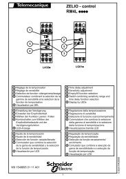
Identifying the electricalauxiliariesElectrical diagramsFixed and drawout devicesThe diagram is shown with circuitsde-energised, all devices open, connectedand charged and relays in normal position.PowerControl unitRemote operationDB101401Control unitCom UC1 UC2 UC3 UC4 / M2C / M6CE5 E6 Z5 M1 M2 M3 F2+ V3 / 484 / Q3Remote operationSDE2 / Res SDE1 MN / MX2 MX1 XF PF MCH184 / K2 84 D2 / C12 C2 A2 254 B2E3 E4 Z3 Z4 T3 T4 VN V2 / 474 / Q2182 82 C3 A3 252 B3E1 E2 Z1 Z2 T1 T2 F1 – V1 / 471 / Q1181 / K1 81 D1 / C11 C1 A1 251 B1A P Hc c cc c cc c cc c cc c cc c cccccccccControl unitCom: E1-E6 communicationUC1: Z1-Z5 zone selective interlocking;Z1 = ZSI OUT SOURCEZ2 = ZSI OUT; Z3 = ZSI IN SOURCEZ4 = ZSI IN ST (short time)Z5 = ZSI IN GF (earth fault)M1 = Vigi module input (Micrologic 7)UC2: T1, T2, T3, T4 = external neutral;M2, M3 = Vigi module input(Micrologic 7)UC3: F2+, F1– external 24 V DC powersupplyVN external voltage connectorUC4: V1, V2, V3 optional external voltageconnectororM2C: 2 programmable contacts (internalrelay); ext. 24 V DC power supplyrequiredorM6C: 6 programmable contacts (externalrelay); ext. 24 V DC power supplyrequired.Remote operationSDE2: Fault-trip indication contactorRes: Remote resetSDE1: Fault-trip indication contact (supplied as standard)MN: Undervoltage releaseorMX2: Shunt releaseMX1: Shunt release (standard or communicating)XF:PF:Closing release (standard or communicating)"Ready to close" contactMCH: Gear motor (*)Note:When communicating MX or XF releases are used, the third wire(C3, A3) must be connected even if the communications module isnot installed.A: Digital ammeterP: A + power meter + programmable protectionH: P + harmonics28<strong>Masterpact</strong> <strong>NT06</strong>-<strong>16</strong> <strong>IEC</strong>Schneider Electric
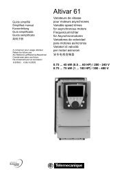
Indication contactsChassis contactsDB101406Indication contactsOF4 OF3 OF2 OF1DB101407Chassis contactsCD2 CD1 CE3 CE2 CE1 CT144 34 24 1442 32 22 1241 31 21 11824 814 334 324 314 914822 812 332 322 312 912821 811 331 321 311 911Indication contactsOF4 / OF3 / OF2 / OF1: ON/OFF indication contactsChassis contactsCD2-CD1:DisconnectedpositionCE3-CE2-CE1:ConnectedpositionCT1:Test-positioncontacts(*) 440/480 V AC gear motor for charging(380 V motor + additional resistor)CN1 - 440/480 V9 11440/480 V"charged LED"RB3B2MCH380VCHE60075ACN2B1- 440/480 VKey:Drawout device onlyXXXSDE1, OF1, OF2, OF3, OF4 supplied as standardInterconnected connections(only one wire per connection point)29<strong>Masterpact</strong> <strong>NT06</strong>-<strong>16</strong> <strong>IEC</strong>Schneider Electric
Discovering <strong>Masterpact</strong>’saccessoriesMicrologic control unitsE46108AFor more in-depth information, see thecontrol-unit user manual.E51329AMicrologic control unitsb standard equipment,one per deviceb long-time rating plugand connectors notincluded, see below:Micrologic 2.0Micrologic 5.0Micrologic 2.0AMicrologic 5.0AMicrologic 6.0AMicrologic 7.0AMicrologic 5.0PMicrologic 6.0PMicrologic 7.0PMicrologic 5.0HMicrologic 6.0HMicrologic 7.0Hb connectors for A, P, H:v for fixed devicev for drawout device.b depending on themodel, control units offerin addition:v fault indicationsv measurement ofelectrical parameters(current, voltage, power,etc.)v harmonic analysisv communication.Long-time rating plugsb standard equipment,one per control unitb setting options:v standard 0.4 to 1 x Irsettingv low 0.4 to 0.8 x Irsettingv high 0.8 to 1 x Irsettingv off (no long-timeprotection).b the plugs determinethe setting range for thelong-time protection.M2C and M6C programmable contactsb optional equipment,used with Micrologic Pand H control unitsb connectors notincluded, see below:v 2 M2C contactsv 6 M6C contactsb connectors:v for fixed devicev for drawout device.b contacts can beprogrammed using thekeypad on the controlunit or via the COMoptionb they indicate:v the type of faultv instantaneous ordelayed thresholdoverruns.b M2C: 2 contacts(5 A - 240 V)b M6C: 6 contacts(5 A - 240 V).b permissible load oneach of the M6C relayoutputs at cos ϕ = 0.7v 240 V AC: 5 Av 380 V AC: 3 Av 24 V DC: 1.8 Av 48 V DC: 1.5 Av 125 V DC: 0.4 Av 250 V DC: 0.15 Ab M2C: 24 V DC ± 5 %power from control unitb M6C: 24 V DC ±5 %external supplyb maximumconsumption: 100 mA.30<strong>Masterpact</strong> <strong>NT06</strong>-<strong>16</strong> <strong>IEC</strong>Schneider Electric
Indication contactsON/OFF indication contacts (OF)b standard equipment,4 OF per devicev standardv low levelb connectors:v for fixed devicev for drawout device.b OF contacts indicatethe position of the maincontactsb they trip when theminimum isolationdistance between themain contacts is reached.b 4 changeover contactsb breaking capacity atcos ϕ = 0.3 (AC12 /DC12 as per 947-5-1)v standard, minimumcurrent 10 mA / 24 VV AC 240/380 6 A (rms)480 6 A (rms)690 6 A (rms)V DC 24/48 2.5125 0.5250 0.3v low level, minimumcurrent 1 mA / 4 VV AC 24/48 5 A (rms)240 5 A (rms)380 5 A (rms)V DC 24/48 5 / 2.5 A125 0.5 A250 0.3 A"Fault-trip" indication contact (SDE/1)b standard equipment oncircuit breakers, oneSDE/1 contact perdeviceb not available for switchdisconnectorversions.b the contact provides aremote indication ofdevice opening due to anelectrical fault.b changeover contactb breaking capacity atcos ϕ = 0.3 (AC12 /DC12 as per 947-5-1)v standard, minimumcurrent 10 mA / 24 VV AC 240/380 5 A (rms)480 5 A (rms)690 3 A (rms)V DC 24/48 3 A125 0.3 A250 0.15 Av low level, minimumcurrent 1 mA / 4 VV AC 24/48 3 A (rms)240 3 A (rms)380 3 A (rms)V DC 24/48 3 A125 0.3 A250 0.15 AE60054AAdditional "fault-trip" indication contact (SDE/2)b optional equipment forcircuit breakers, oneadditional SDE/2 contactper deviceb not available for switchdisconnectorversionsb not compatible with theRes optionb connectors notincluded, see below:v standardv low levelb connectors:v for fixed devicev for drawout device.b the contact remotelyindicates device openingdue to an electrical fault.b changeover contactb breaking capacity atcos ϕ = 0.3 (AC12 /DC12 as per 947-5-1)v standard, minimumcurrent 10 mA / 24 VV AC 240/380 5 A (rms)480 5 A (rms)690 3 A (rms)V DC 24/48 3 A125 0.3 A250 0.15 Av low level, minimumcurrent 1 mA / 4 VV AC 24/48 3 A (rms)240 3 A (rms)380 3 A (rms)V DC 24/48 3 A125 0.3 A250 0.15 A31<strong>Masterpact</strong> <strong>NT06</strong>-<strong>16</strong> <strong>IEC</strong>Schneider Electric
Discovering <strong>Masterpact</strong>’saccessoriesIndication contactsE60050AElectrical reset after fault trip (Res)b optional equipment,one Res per deviceb not compatible with theSDE/2 optionb connectors notincluded, see below:v 110/130 V ACv 220/240 V ACb connectors:v for fixed devicev for drawout device.b the contact remotelyresets the devicefollowing tripping due toan electrical fault."Springs charged" limit switch contact (CH)b equipment includedwith MCH gear motor,one CH contact perdevice.b the contact indicatesthe "charged" status ofthe operating mechanism(springs charged).b changeover contactb breaking capacity 50/60 Hz for AC power(AC12 / DC12 as per947-5-1):V AC 240 10A(rms)380 6 A (rms)480 6 A (rms)690 3 A (rms)V DC 24/48 3 A125 0.5 A250 0.25 AE51332A"Ready to close" contact (PF)b optional equipment,one PF contact perdeviceb connectors notincluded, see below:v standardv low levelb connectors:v for fixed devicev for drawout device.b the contact indicatesthat the device may beclosed because all thefollowing are valid:v circuit breaker is openv spring mechanism ischargedv a maintained closingorder is not presentv a maintained openingorder is not present.b changeover contactb breaking capacity atcos ϕ = 0.3 (AC12 /DC12 as per 947-5-1)v standard, minimumcurrent 10 mA / 24 VV AC 240/380 5 A (rms)480 5 A (rms)690 3 A (rms)V DC 24/48 3 A125 0.3 A250 0.15 Av low level, minimumcurrent 1 mA / 4 VV AC 24/48 3 A (rms)240 3 A (rms)380 3 A (rms)V DC 24/48 3 A125 0.3 A250 0.15 A32<strong>Masterpact</strong> <strong>NT06</strong>-<strong>16</strong> <strong>IEC</strong>Schneider Electric
Auxiliaries for remote operationE46790AGear motor (MCH)b optional equipment,one MCH gear motor perdeviceb connectors notincluded, see below:v AC 50 / 60 Hz:48/60100/130200/240277/415440/480v DC24/3048/60100/125200/250b connectors:v for fixed devicev for drawout device.b the gear motorautomatically charges thespring mechanism.b power supply:v V AC 50/60 Hz: 48/60100/130 - 200/240 - 277400/440 - 480v V DC: 24/30 - 48/60100/125 - 200/250b operating threshold:0.85 to 1.1 Unb consumption:180 VA or Wb inrush current:2 to 3 In for 0.1 secondb charging time:3 seconds max.b operating rate:maximum 3 cycles perminuteb CH contact: see page32.E51294AOpening releases MX/1 and MX/2, closing release XFb optional equipment, 1or 2 MX releases perdevice, 1 XF per deviceb the function (MX or XF)is determined by wherethe coil is installedb connectors notincluded, see belowV AC 50/60 Hz, V DC:v standard version:12 DC24/30 AC/DC48/60 AC/DC100/130 AC/DC200/250 AC/DC240/277 AC380/480 ACv communicating version(with COM option):12 DC24/30 AC/DC48/60 AC/DC100/130 AC/DC200/250 AC/DC240/277 AC380/480 ACb connectors:v for fixed devicev for drawout device.b the MX releaseinstantaneously opensthe circuit breaker whenenergisedb the XF releaseinstantaneously closesthe circuit breaker whenenergised, if the device is"ready to close".b power supply:v V AC 50 / 60 Hz:24 48 - 100/130 - 200/250 240/277 - 380/480v V DC: 12 - 24/3048/60 - 100/130200/250b operating threshold:v XF: 0.85 to 1.1 Unv MX: 0.7 to 1.1 Unb consumption:v pick-up: 200 VA or W(80 ms)v hold: 4.5 VA or Wb circuit-breakerresponse time at Un:v XF: 55 ms ± 10v MX: 50 ms ± 10.33<strong>Masterpact</strong> <strong>NT06</strong>-<strong>16</strong> <strong>IEC</strong>Schneider Electric
Discovering <strong>Masterpact</strong>’saccessoriesAuxiliaries for remote operationE51294AInstantaneous undervoltage releases (MN)b optional equipment,1 MN per deviceb not compatible with theMX/2 opening releaseb connectors notincluded, see belowV AC 50/60 Hz, V DC:24/30 AC/DC48/60 AC/DC100/130 AC/D200/250 AC/DC380/480 ACb connectors:v for fixed devicev for drawout device.b the MN releaseinstantaneously opensthe circuit breaker whenits supply voltage drops.b power supply:v V AC 50/60 Hz: 24/48100/130 - 200/250240/277 - 380/480v V DC: 24/30 - 48/60100/130 - 200/250b operating threshold:v opening: 0.35 to 0.7 Unv closing: 0.85 Unb consumption:v pick-up: 200 VA or W(80 ms)v hold: 4.5 VA or Wb circuit-breakerresponse time at Un:40 ms ± 10.E51296ADelay unit for MN releases1 2 3 4 5 63 6MNUVR100/130 VAC/DC10121 2 3S0.5 13 1.5Retardateur de MNTime delay for UVRb optional equipment,1 MN with delay unit perdeviceb delay-unitV AC 50/60 Hz, V DC:v non adjustable:100/130 AC/DC200/250 AC/DCv adjustable:48/60 AC/DC100/130 AC/DC200/250 AC/DC380/480 AC/DC.b the unit delaysoperation of the MNrelease to eliminatecircuit-breaker nuisancetripping during shortvoltage dipsb the unit is wired inseries with the MN andmust be installed outsidethe circuit breaker.b power supply V AC 50/60 Hz, V DC:v non adjustable:100/130 - 200/250v adjustable:48/60 - 100/130200/250 - 380/480b operating threshold:v opening: 0.35 to 0.7 Unv closing: 0.85 Unb consumption:v pick-up: 200 VA or W(80 ms)v hold: 4.5 VA or Wb circuit-breakerresponse time at Un:v non adjustable:0.25 secondv adjustable: 0.5 - 0.9 -1.5 - 3 seconds.E60344AElectrical closing pushbutton (BPFE)b optional equipment,1 BPFE per device.b located on the padlockor keylock lockingsystem, this pushbuttoncarries out electricalclosing of the circuitbreaker via the XFrelease, taking intoaccount all the safetyfunctions that are part ofthe control/monitoringsystem of the installationb it connects to the inputof the COM option.34<strong>Masterpact</strong> <strong>NT06</strong>-<strong>16</strong> <strong>IEC</strong>Schneider Electric
Wiring of control auxiliariesUnder pick-up conditions, the level of consumption is approximately 150 to 200 VA.Consequently, for low supply voltages (12, 24, 48 V), cables must not exceed amaximum length determined by the supply voltage and the cross-section of thecables.Indicative values for maximum cable lengths (in meters)12 V 24 V 48 V2.5 mm 2 1.5 mm 2 2.5 mm 2 1.5 mm 2 2.5 mm 2 1.5 mm 2MN 100%source voltage — — 58 36 280 <strong>16</strong>585%source voltage — — <strong>16</strong> 10 75 45MX / XF 100%source voltage 21 12 115 70 550 33085%source voltage 10 6 75 44 350 210Note. The indicated length is that for each of the two supply wires.35<strong>Masterpact</strong> <strong>NT06</strong>-<strong>16</strong> <strong>IEC</strong>Schneider Electric
Discovering <strong>Masterpact</strong>’saccessoriesDevice mechanical accessoriesE47341A00399Operation counter (CDM)b optional equipment,one CDM per device.b the operation countersums the number ofoperating cycles.E60499AEscutcheon (CDP)b optional equipment,one CDP per devicev for fixed devicev for drawout device.b the CDP increases thedegree of protection to IP40 and IK 07 (fixed anddrawout devices).E60497ATransparent cover (CCP)b optional equipment,one CCP per deviceequipped with a CDPb for drawout devices.b mounted with a CDP,the CCP increases thedegree of protection toIP 54 and IK 10 (fixedand drawout devices).E60498ABlanking plate (OP)b optional equipment,one OP per device.b used with theescutcheon, this optioncloses off the doorcut-out of a cubicle notyet equipped with adevice. It may be usedwith the escutcheon forboth fixed and drawoutdevices.36<strong>Masterpact</strong> <strong>NT06</strong>-<strong>16</strong> <strong>IEC</strong>Schneider Electric
Device mechanical accessoriesE60347ATransparent cover for pushbutton locking using a padlock,lead seal or screwsb optional equipment,one locking cover perdevice.b the transparent coverblocks access (togetheror separately) to thepushbuttons used toopen and close thedeviceb locking requires apadlock, a lead seal ortwo screws.E60346ADevice locking in the OFF position using a padlockb optional equipment,one locking system perdevice.b the unit inhibits local orremote closing of thedeviceb up to three padlocksmay be used for locking.E60348ADevice OFF position locking kit for keylocksb optional equipment:one locking kit (withoutkeylock) per devicev for Profalux keylov for Ronis keylockv for Kirk keylocksv for Castell keyloc.b optional equipment,one locking system perdevice.b the kit inhibits local orremote closing of thedevice.E51286AE51287ARonisProfaluxKeylocks required for the device OFF position locking kitb one or two keylocksper locking kitv Ronis:1 keylockv Profalux:1 keylock.37<strong>Masterpact</strong> <strong>NT06</strong>-<strong>16</strong> <strong>IEC</strong>Schneider Electric
Discovering <strong>Masterpact</strong>’saccessoriesChassis accessoriesTop shutter closedBottom shutter closedSafety shuttersE60030AE60031Ab optional equipmentb (set of shutters for topand bottom) drawout,front/rear connection:v 3 polesv 4 poles.b mounted on thechassis, the safetyshutters automaticallyblock access to thedisconnecting contactcluster when the deviceis in the "disconnected"or "test" positions.b IP 20 for chassisconnectionsb IP 40 for thedisconnecting contactcluster.If specified when ordering the chassis, thislocking function may be adapted to operatein all positions ("connected", "test" and"disconnected"), instead of in"disconnected" position alone.Circuit breaker locking in "disconnected" positionb optional equipment,one locking system perdeviceb keylocks not included:v for Profalux keylocksv for Ronis keylocksv for Castell keylocksv for Kirk keylocks.b mounted on thechassis and accessiblewith the door closed, thissystem locks the circuitbreaker in "disconnected"position using one or twokeylocks.E51286AE51287ARonisProfaluxE51273AE51274AKeylocks required with the "disconnected" position lockingsystemb one or two keylocksper locking systemv Ronis:1 keylock1 keylock + one identicalkeyloc2 different key locksv Profalux:1 keyl1 keylock + one identicalkeylock2 different key locks.38<strong>Masterpact</strong> <strong>NT06</strong>-<strong>16</strong> <strong>IEC</strong>Schneider Electric
Chassis accessoriesE60011AOpush OFFDoor interlockb optional equipment,one door interlock perchassis.b this device inhibitsopening of the cubicledoor when the circuitbreaker is in "connected"or "test" position.b it may be mounted onthe left or right-hand sideof the chassis.O OFFE46095A E60345AE59190AE51498ARacking interlockb optional equipment,one racking interlock perchassis.Mismatch protectionb optional equipment,one mismatch protectiondevice per chassis.Auxiliary terminal shield (CB)b optional equipment,one CB shield perchassis:3 poles4 poles.b this device preventsinsertion of the rackinghandle when the cubicledoor is open.b mismatch protectionoffers twenty differentcombinations that theuser may select toensure that only acompatible circuitbreaker is mounted on agiven chassis.b the shield preventsaccess to the terminalblock of the electricalauxiliaries.b it is mounted on theright-hand side of thechassis."Connected", "disconnected" and "test" position carriageswitches (CE, CD, CT)b optional equipment,one to six carriageswitchesb standard configuration,0 to 3 CE, 0 to 2 CD,0 to 1 CT.v standardv low level.b the carriage switchesindicate the threepositions:CE: connected positionCD: disconnectedposition (when theminimum isolationdistance between themain contacts and theauxiliary contacts isreached)CT: test position.b changeover contactb breaking capacity atcos ϕ = 0.3 (AC12 /DC12 as per 947-5-1)v standard, minimumcurrent 10 mA / 24 VV AC 240 8 A (rms)380 8 A (rms)480 8 A (rms)690 6 A (rms)V DC 24/48 2.5 A125 0.8 A250 0.3 Av low level, minimumcurrent 1 mA / 4 VV AC 24/48 5 A (rms)240 5 A (rms)380 5 A (rms)V DC 24/48 2.5 A125 0.8 A250 0.3 A39<strong>Masterpact</strong> <strong>NT06</strong>-<strong>16</strong> <strong>IEC</strong>Schneider Electric
Inspecting and testingbefore useInitial testsProcedureThese operations must be carried out inparticular before using a <strong>Masterpact</strong> devicefor the first time.A general check of the circuit breaker takes only a few minutes and avoids any riskof mistakes due to <strong>error</strong>s or negligence.A general check must be carried out:b prior to initial useb following an extended period during which the circuit breaker is not used.A check must be carried out with the entire switchboard de-energised.In switchboards with compartments, only those compartments that may beaccessed by the operators must be de-energised.Electrical testsInsulation and dielectric-withstand tests must be carried out immediately afterdelivery of the switchboard. These tests are precisely defined by internationalstandards and must be directed and carried out by a qualified expert.Prior to running the tests, it is absolutely necessary to:b disconnect all the electrical auxiliaries of the circuit breaker (MCH, MX, XF, MN,Res electrical remote reset)b remove the long-time rating plug on the 7.0 A, 5.0 P, 6.0 P, 7.0 P, 5.0 H, 6.0 H,7.0 H control units. Removal of the rating plug disconnects the voltagemeasurement input.Switchboard inspectionCheck that the circuit breakers are installed in a clean environment, free of anyinstallation scrap or items (tools, electrical wires, broken parts or shreds, metalobjects, etc.).Conformity with the installation diagramCheck that the devices conform with the installation diagram:b breaking capacities indicated on the rating platesb identification of the control unit (type, rating)b presence of any optional functions (remote ON/OFF with motor mechanism,auxiliaries, measurement and indication modules, etc.)b protection settings (long time, short time, instantaneous, earth fault)b identification of the protected circuit marked on the front of each circuit breaker.Condition of connections and auxiliariesCheck device mounting in the switchboard and the tightness of power connections.Check that all auxiliaries and accessories are correctly installed:b electrical auxiliariesb terminal blocksb connections of auxiliary circuits.OperationCheck the mechanical operation of the circuit breakers:b opening of contactsb closing of contacts.Check on the control unitCheck the control unit of each circuit breaker using the respective user manuals.40<strong>Masterpact</strong> <strong>NT06</strong>-<strong>16</strong> <strong>IEC</strong>Schneider Electric
What to do when the circuitbreaker tripsNote the faultFaults are signalled locally and remotely by the indicators and auxiliary contactsinstalled on circuit breakers (depending on each configuration). See page 12 in thismanual and the user manual of the control unit for information on the faultindications available with your circuit breaker.Identify the cause of trippingA circuit must never be reclosed (locally or remotely) before the cause of the faulthas been identified and cleared.A fault may have a number of causes:b depending on the type of control unit, fault diagnostics are available. See theuser manual for the control unit.b depending on the type of fault and the criticality of the loads, a number ofprecautionary measures must be taken, in particular the insulation and dielectrictests on a part of or the entire installation. These checks and test must be directedand carried out by qualified personnel.Inspect the circuit breaker following a short-circuitb check the arc chutes (see page 43)b check the contacts (see page 43)b check the tightness of connections (see the device installation manual)b check the disconnecting-contact clusters (see page 43).Reset the circuit breakerThe circuit breaker can be reset locally or remotely. See page 12 in this manual forinformation on how the circuit breaker can be reset.41<strong>Masterpact</strong> <strong>NT06</strong>-<strong>16</strong> <strong>IEC</strong>Schneider Electric
Maintaining <strong>Masterpact</strong>performanceRecommended maintenanceprogramRecommended program for devices usedunder normal operating conditions:Ambient temperature: -5 °C / +70 °CNormal atmospherePeriodic inspections requiredInterval Operation Procedureeach year b open and close the device v see pages 10 and 11locally and remotely,successively using the variousauxiliariesb test the operating sequences v see pages 10 and 11b test the control unit using v see the user manual ofthe mini test kitthe control unitevery two years or b check the arc chutes v see page 43when the control-unit b check the main contacts v see page 43maintenance indicator b check the tightness v see the devicereaches 100 of connections installation manualParts requiring replacement, depending on the number ofoperating cyclesThe following parts must be replaced periodically to lengthen the service life of thedevice (maximum number of operating cycles).Part Intervening entity Description orprocedurearc chutes b user v see page 43main contacts b inspection: user v see page 43b replacement:Schneider After Sales SupportMCH gear motor b user v see page 9mechanical interlocks b userconnecting-rod b Schneider After SalesspringsSupportMX/MN/XF b user v see pages 10 and 11Part replacement must be programmed on the basis of the data below, listing theservice life of the various parts in numbers of O/C cycles at the rated current.Number of O/C cycles at the rated currentType of Maximum Maximum service life incircuit service life electrical durabilitybreaker in mechanicaldurabilityMX / XF / MNreleasesNT08 to <strong>16</strong> 12500 440 V: 6000 12500type H1/H2 690 V: 3000NT08 to 10 12500 440 V: 3000 12500type L1 690 V: 200042<strong>Masterpact</strong> <strong>NT06</strong>-<strong>16</strong> <strong>IEC</strong>Schneider Electric
Maintenance operationsBefore undertaking any maintenance work,de-energise the installation and fit locks orArc chutesb remove the fixing screwswarnings in compliance with all applicablesafety standards. 12E60045AE60000Ab check the arc chutes:v chamber intactv separators not corroded.If necessary, replace the arc chutes.E60001A3E60002Ab refit the arc chutes and secure with a tightening torque of 1.5 Nm.If the control unit has a maintenanceindicator, there is no need to systematicallycheck the contacts.If the contacts are worn, have theconcerned poles replaced by the Schneiderservice centre.Wear of main contactsb remove the arc chutesb visually check the contacts.If necessary, contact Schneider After-sales support.Disconnecting-contact clustersb grease the contacts using the grease recommended on page 44, supplied bySchneider Electricb check the contacts as follows:v open the circuit breakerv de-energise the busbarsv disconnect the circuit breakerv remove the circuit breakerv check the contact fingers (no sign of copper should be visible).Replace any worn clusters.43<strong>Masterpact</strong> <strong>NT06</strong>-<strong>16</strong> <strong>IEC</strong>Schneider Electric
Maintaining <strong>Masterpact</strong>performanceOrdering replacement partsElectrical accessoriesThe electrical accessories that may require replacement are the following:b MCH gear motorb MX opening release(s)b XF closing releaseb MN undervoltage release.See pages 33 and 34 in the "Auxiliaries for remote operation" section for theircharacteristics.E60002AArc chutesb 1 arc chute:v type H1v type L1.b one chute per pole.E60349AFrontb 1 per 3- or 4-poledevice.E60496ACharging handleb 1 per device.E51336ACrankb 1 per device.Support for MX / XF / MN releasesb 1 per device.E46237ADisconnecting-contact clustersb 1 cluster.Grease for disconnecting-contact clustersb 1 can.44<strong>Masterpact</strong> <strong>NT06</strong>-<strong>16</strong> <strong>IEC</strong>Schneider Electric
45<strong>Masterpact</strong> <strong>NT06</strong>-<strong>16</strong> <strong>IEC</strong>Schneider Electric
Maintaining <strong>Masterpact</strong>performanceTroubleshooting andsolutionsProblem Probable causes Solutionscircuit breaker cannot be closed locally or remotely b circuit breaker padlocked or v disable the locking fonctionkeylocked in the "open" positionb circuit breaker interlockedmechanically in a source changeoversystemb circuit breaker not completely connectedv check the position of the othercircuit breaker in the changeoversystemv modify the situation to release theinterlockv terminate racking in (connection)of the circuit breakerb the reset button signalling a fault trip v clear the faulthas not been resetv push the reset button on the frontof the circuit breakerb stored energy mechanism not charged v charge the mechanism manuallyv if it is equipped with a an MCH gearmotor, check the supply of power tothe motor. If the problem persists,replace the gear motor (MCH)b MX opening shunt releasev there is an opening order.permanently supplied with powerDetermine the origin of the order. Theorder must be cancelled before thecircuit breaker can be closedb MN undervoltage release not supplied v there is an opening order.with powerDetermine the origin of the order.v check the voltage and the supplycircuit (U > 0.85 Un). If the problempersists, replace the releaseb XF closing release continuously v cut the supply of power to the XFsupplied with power, but circuit breaker not closing release, then send the closing"ready to close" (XF not wired in series order again via the XF, but only if thewith PF contact)circuit breaker is "ready to close"b permanent trip order in the presence of v Disable these protection functionsa Micrologic P or H control unit with on the Micrologic P or H control unitminimum voltage and minimum frequencyprotection in Trip mode and the controlunit poweredcircuit breaker cannot be closed remotely but can be b closing order not executed by the XF v check the voltage and the supplyopened locally using the closing pushbutton closing release circuit (0.85 - 1.1 Un). If the problempersists, replace the XF releaseunexpected tripping without activation of the reset b MN undervoltage release supply v check the voltage and the supplybutton signalling a fault trip voltage too low circuit (U > 0.85 Un)b load-shedding order sent to the MXopening release by another devicev check the overall load on thedistribution systemv if necessary, modify the settings ofdevices in the installationb unnecessary opening order from the v determine the origin of the orderMX opening releaseunexpected tripping with activation of the reset button a fault is present :signalling a fault trip b overload v determine and clear the causes ofb earth faultthe faultb short-circuit detected by the control v check the condition of the circuitunitbreaker before putting it back intoserviceinstantaneous opening after each attempt to close the b thermal memory v see the user manual of the controlcircuit breaker with activation of the reset buttonsignalling a fault tripb transient overcurrent when closingb closing on a short-circuitunitv press the reset buttonv modify the distribution system or thecontrol-unit settingsv check the condition of the circuitbreaker before putting it back intoservicev press the reset buttonv clear the faultv check the condition of the circuitbreaker before putting it back intoservicev press the reset button46<strong>Masterpact</strong> <strong>NT06</strong>-<strong>16</strong> <strong>IEC</strong>Schneider Electric
Problem Probable causes Solutionscircuit breaker cannot be opened remotely, but can be b opening order not executed by the MX v check the voltage and the supplyopened locally opening release circuit (0.7 - 1.1 Un).If the problem persists, replace theMX releaseb opening order not executed by the MNundervoltage releasev drop in voltage insufficient orresidual voltage (> 0.35 Un) acrossthe terminals of the undervoltagerelease. If the problem persists,replace the MN releasecircuit breaker cannot be opened locally b operating mechanism malfunction or v contact a Schneider service centrewelded contactscircuit breaker cannot be reset locally but not remotely b insufficient supply voltage for the v check the voltage and the supplyMCH gear motorcircuit (0.7 - 1.1 Un).If the problem persists, replace theMCH releasenuisance tripping of the circuit breaker with activation b reset button not pushed-in completely v push the reset button in completelyof the reset button signalling a fault tripimpossible to insert the crank in connected, test or b a padlock or keylock is present on the v disable the locking functiondisconnected positionchassis or a door interlock is presentimpossible to turn the crank b the reset button has not been pressed v press the reset buttoncircuit breaker cannot be removed from chassis b circuit breaker not in disconnected v turn the crank until the circuitpositionbreaker is in disconnected positionand the reset button outb the rails are not completely outv pull the rails all the way outcircuit breaker cannot be connected (racked in) b chassis/circuit breaker mismatch v check that the chassis correspondsprotectionwith the circuit breakerb the safety shutters are lockedv remove the lock(s)b the disconnecting-contact clusters are v reposition the clustersincorrectly positionedb chassis locked in disconnectedv disable the chassis locking functionpositionb the reset button has not been pressed, v press the reset buttonpreventing rotation of the crankb the circuit breaker has not been v insert the circuit breaker completelysufficiently inserted in the chassis so that it is engaged in the rackingmechanismcircuit breaker cannot be locked in disconnected b the circuit breaker is not in the right v check the circuit breaker position byposition position making sure the resett button is outb the cranck is still in the chassisv remove the crank and store itcircuit breaker cannot be locked in connected, test or b check that locking in any position is v contact a Schneider service centredisconnected positionenabledb the circuit breaker is not in the right v check the circuit breaker position bypositionmaking sure the rese button is outb the cranck is still in the chassisv remove the crank and store it47<strong>Masterpact</strong> <strong>NT06</strong>-<strong>16</strong> <strong>IEC</strong>Schneider Electric
Checking <strong>Masterpact</strong>operating conditionsE60005A E60004AE60003AAmbient temperature<strong>Masterpact</strong> NT devices can operate under the following temperature conditions:b the electrical and mechanical characteristics are stipulated for an ambienttemperature of -5 °C to +70 °Cb circuit-breaker closing is guaranteed down to -35 °Cb <strong>Masterpact</strong> NW (without the control unit) can be stored in an ambienttemperature of -40 °C to +85 °Cb the control unit can be stored in an ambient temperature of -25 °C to +85 °C.Extreme atmospheric conditions<strong>Masterpact</strong> NT devices have successfully passed the tests defined by the followingstandards for extreme atmospheric conditions:b <strong>IEC</strong> 68-2-1: dry cold at -55 °Cb <strong>IEC</strong> 68-2-2: dry heat at +85 °Cb <strong>IEC</strong> 68-2-30: damp heat (temperature +55 °C, relative humidity 95%)b <strong>IEC</strong> 68-2-52 level 2: salt mist.<strong>Masterpact</strong> NT devices can operate in the industrial environments defined bystandard <strong>IEC</strong> 947 (pollution degree up to 4).It is nonetheless advised to check that the devices are installed in suitably cooledswitchboards without excessive dust.Vibrations<strong>Masterpact</strong> NT devices resist electromagnetic or mechanical vibrations.Tests are carried out in compliance with standard <strong>IEC</strong> 68-2-6 for the levels requiredby merchant-marine inspection organisations (Veritas, Lloyd’s, etc.):b 2 to 13.2 Hz: amplitude ±1 mmb 13.2 to 100 Hz: constant acceleration 0.7 g.Excessive vibration may cause tripping, breaks in connections or damage tomechanical parts.48<strong>Masterpact</strong> <strong>NT06</strong>-<strong>16</strong> <strong>IEC</strong>Schneider Electric
E60006AAltitude<strong>Masterpact</strong> NT devices are designed for operation at altitudes under 2000 metres.At altitudes higher than 2000 metres, the modifications in the ambient air(electrical resistance, cooling capacity) lower the following characteristics.2000 maltitude (m) 2000 3000 4000 5000dielectric withstand 3500 3150 2500 2100voltage (V)rated insulation level (V) 1000 900 700 600rated operational 690 590 520 460voltage (V)rated current (A) at 40 °C 1 x In 0.99 x In 0.96 x In 0.94 x InE60007AElectromagnetic disturbances<strong>Masterpact</strong> NT devices are protected against:b overvoltages caused by devices that generate electromagnetic disturbancesb overvoltages caused by an atmospheric disturbance or by a distribution-systemoutage (e.g. failure of a lighting system)b devices emitting radio waves (radios, walkie-talkies, radar, etc.)b electrostatic discharges produced by users.<strong>Masterpact</strong> NT devices have successfully passed the electromagnetic-compatibilitytests (EMC) defined by the following international standards:b <strong>IEC</strong> 947-2, appendix Fb <strong>IEC</strong> 947-2, appendix B (trip units with earth-leakage function).The above tests guarantee that:b no nuisance tripping occursb tripping times are respected.Cleaningv non-metallic parts:never use solvent, soap or any other cleaning product. Clean with a dry cloth onlyv metal parts:clean with a dry cloth whenever possible. If solvent, soap or any other cleaningproduct must be used, make sure that it does not come into contact withnon-metallic parts.49<strong>Masterpact</strong> <strong>NT06</strong>-<strong>16</strong> <strong>IEC</strong>Schneider Electric
Schneider Electric Industries SAS5, rue Nadar92506 Rueil-Malmaison CedexFranceTel: +33 (0)1 41 29 82 00Fax:+33 (0)1 47 51 80 20http://www.schneider-electric.comhttp://www.merlin-gerin.comAs standards, specifications and designs develop from time, always ask for confirmation of theinformation given in this publication.Printed on recycled paperDesigned by: SEDOCPhotos: SchneiderPrinted by:512011<strong>16</strong>AA-E1 11-2006