Altivar 58 Telemecanique - error
Altivar 58 Telemecanique - error
Altivar 58 Telemecanique - error
- No tags were found...

Create successful ePaper yourself
Turn your PDF publications into a flip-book with our unique Google optimized e-Paper software.
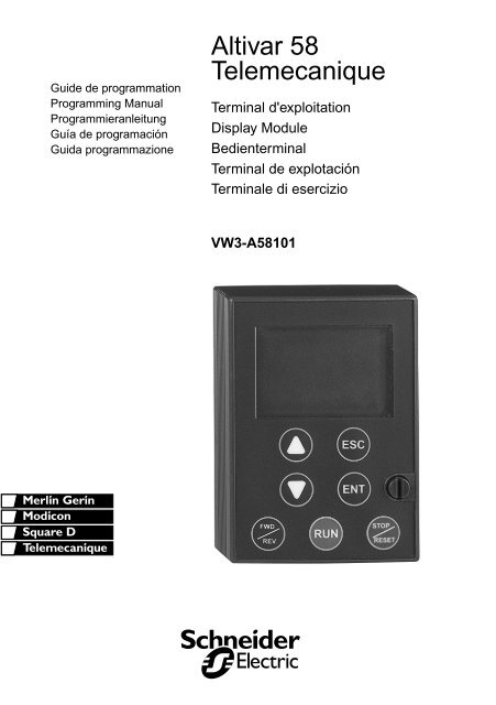
Altvar <strong>58</strong>Terminal d’exploitation Page 2Display Module Page 60Bedienterminal Seite 118Terminal de explotación Página 176Terminale di esercizio Pagina 234FRANÇAIS ENGLISH DEUTSCH ESPAÑOL ITALIANO3
Practical Advice / Minimum SetupPractical advice :Before starting your programming, first fill in the configuration and settings record tables (at the end of thisdocument).Programming the <strong>Altivar</strong> <strong>58</strong> is made easier by the use of internal sequence selections and interlocks. In orderto maximize this ease of use, we recommend that you access the menus in the following order. Not all stepsare essential in every case.↓↓LANGUAGEMACRO-CONFIGIDENTIFICATIONCONTROL (for 3-wire control only)I/OCONTROLDRIVEFAULTCOMMUNICATION or APPLICATION if a card is usedADJUSTCAUTION : The user must ensure that the programmed functions are compatible with the wiringdiagram used. This check is particularly important on the ready-assembled ATV<strong>58</strong>E if the factoryconfiguration is modified; the diagram may also require modification.ENGLISHMinimum setup :This procedure can be used :- in simple applications where the speed controller factory settings are suitable- in installation phases where it is necessary to rotate the motor experimentally before undertaking a fullinstallationProcedure :1 Follow the recommendations in the User's Manual supplied with the speed controller, most importantlysetting the 50/60 Hz selector switch to the nominal frequency of the motor.2 Ensure that the factory macro-configuration is suitable, otherwise change it in the «MACRO-CONFIG»menu.3 For speed controllers with power ratings greater than 7.5 kW at 200/240 V and 15 kW at 380/500 V in"standard torque" applications, configure the power in the «IDENTIFICATION» menu.4 To ensure the required level of safety, check that the wiring diagram is compatible with the macroconfiguration,otherwise modify the diagram.5 Check in the «DRIVE» menu that the factory parameters are compatible with those given on the motorrating plate, otherwise modify them.6 In the «DRIVE» menu, perform an auto tune.7 If necessary, adjust the parameters in the «ADJUST» menu (ramps, thermal current, etc).67
Access to MenusThe number of menus which can be accessed depends on the position of the access locking switch.Each menu is made up of a number of parameters.Initialpower-upSubsequentpower-upsESCLANGUAGEMACRO-CONFIGLnGCFGrEF0.37 kW 200/240 VSUP1-DISPLAYIdentificationENGLISHSEt2-ADJUSTdrC3-DRIVECtL4-CONTROL5-I/OI-OThe PROGindication isdisplayed onthe display moduleFLt6-FAULTFLS7-FILEScan only be accessed if the"client application" card isinstalledAPP8-APPLICATIONSL8-COMMUNICATIONcan only be accessed ifthe protocol card isinstalledCAUTION : If an access code has already been programmed, it may be impossible to modify some menus,these may not even be visible. In this case, see the section entitled “FILES menu” explaining how to enter theaccess code.69
Macro-ConfigurationsModification of the macro-configuration requires double confirmation as it results in automaticassignment of functions and a return to factory settings.The following screen is displayed :WIRING OK?CHGENTENT to confirm the modificationESC to return to the previous configurationENGLISHCustomizing the configuration :The configuration of the speed controller can be customized by changing the I/O assignment in the I/O menuwhich can be accessed in programming mode (access switch in position ).This customization modifies the displayed macro-configuration value :is displayed.CFGCUS:Customize72
Display MenuDisplay menu (selection of parameter displayed during operation)The following parameters can be accessed whatever position the access switch is in, in stop or run mode.ENGLISHCode Function Unit---rdYrUnACCdECCLIdCbnStObrVar. State –State of the speed controller : indicates a fault or the motor operating phase :rdY = speed controller ready,rUn = motor in steady state or run command present and zero reference,ACC = accelerating,dEC = decelerating,CLI = current limit,dCb = injection braking,nSt = freewheel stop control,Obr = braking by adapting the deceleration ramp (see the “drive” menu).FrH Freq. Ref. HzFrequency referencerFr Output Freq. HzOutput frequency applied to the motorSPd Motor Speed rpmMotor speed estimated by the speed controllerLCr MotorCurrent AMotor currentUSP Mach. speed –Machine speed estimated by the speed controller. This is proportional to rFr, according to acoefficient USC which can be regulated in the adjust menu. Displays a value corresponding to theapplication (metres / second, for example). Caution, if USP becomes greater than 9999 the displayisdivided by 1000.OPr Output power %Power supplied by the motor, estimated by the controller.100 % corresponds to nominal power.ULn MainsVoltage VLine voltagetHr MotorThermal %Thermal state : 100% corresponds to the nominal thermal state of the motor. Above 118%, thespeed controller triggers an OLF fault (motor overload)tHd DriveThermal %Thermal state of the speed controller : 100% corresponds to the nominal thermal state of the speedcontroller. Above 118%, the speed controller triggers an OHF fault (speed controller overheating).It can be reset below 70 %.LFt Last Fault –Displays the last fault which occurred.74
Display MenuCode Function UnitLFr Freq. Ref. HzThis adjustment parameter appears instead of the FrH parameter when the speed controller controlvia the display module is activated : LCC parameter in the control menu.APH Consumption kWh or MWhEnergy consumed.rtH Run time hrsContinuous operating time (motor powered up) in hours.ENGLISH75
Adjust MenuThis menu can be accessed when the switch is in positions and . Adjustment parameterscan be modified in stop mode OR during operation. Ensure that any changes made duringoperation are not dangerous; changes should preferably be made in stop mode.The list of adjustment parameters is made up of a fixed and a changeable part which varies according to :- the selected macro-configuration- the presence of an I/O extension card- the reassignment of I/OThe following parameters can always be accessed in all the macro-configurations.ENGLISHCode Description Adjustment range Factory settingLFr Freq. Ref. - Hz LSP to HSP –Appears when control via the display module is activated : LCC parameter in the control menuACCdECAC2dE2Acceleration - sDeceleration - s0.05 to 999.90.05 to 999.9Acceleration and deceleration ramp times. Ranges 0 to motor nominal frequency (FrS)Accelerate 2 - sDecelerate 2 - s0.05 to 999.90.05 to 999.92nd acceleration ramp2nd deceleration rampThese parameters can be accessed if the ramp switching threshold (parameter Frt) is other than 0Hz or if a logic input is assigned to ramp switching.3 s3 s5 s5 sLSP Low Speed - Hz 0 to HSP 0 HzLow speedHSP High Speed - Hz LSP to tFr 50 / 60 Hzacc. to the switchHigh speed : ensure that this setting is correct for the motor and the application.FLG Gain - % 0 to 100 20Frequency loop gain : used to adapt the rapidity of the machine speed transients according to thedynamics.For high resistive torque, high inertia or fast cycle machines, increase the gain gradually.StA Stability - % 0 to 100 20Used to adapt the return to steady state after a speed transient according to the dynamics of themachine.Gradually increase the stability to avoid any overspeed.ItH ThermCurrent - A 0.25 to 1.36 In (1) According to controller ratingCurrent used for motor thermal protection. Set ItH to the nominal current on the motor rating plate.tdC DC Inj. Time - s 0 to 30 s Cont 0.5 sDC injection braking time.If this is increased to more than 30 s, "Cont" is displayed, permanent DC injection.The injection becomes equal to SdC after 30 seconds.(1) In corresponds to the speed controller nominal current indicated in the catalog and on the speed controlleridentification label for high torque applications.76
Adjust MenuCode Description Adjustment range Factory settingSdC DC stop.curr - A 0.1 to 1.36 In (1) Acc. to contr. ratingInjection braking current applied after 30 seconds if tdC = Cont.Check that motor will withstand this curr. without overheatingJPF Jump Freq. - Hz 0 to HSP 0 HzSkip frequency : prohibits prolonged operation over a frequency range of +/-2.5 Hz around JPF. Thisfunction can be used to prevent a critical speed which causes resonance.JF2 Jump Freq.2 - Hz 0 to HSP 0 HzSecond skip frequency: Same function as JPF, for a second frequency valueJF3 Jump Freq.3 - Hz 0 to HSP 0 HzThird skip frequency: Same function as JPF, for a third frequency valueUSC Machine Coef. 0.01 to 100 1Coefficient applied to parameter rFr (output frequency applied to the motor), the machine speed isdisplayed via parameter USPUSP = rFr x USCtLS LSP Time - s 0 to 999.9 0 (no time limit)Operating time at low speed. After operating at LSP for a given time, the motor is stoppedautomatically. The motor restarts if the frequency reference is greater than LSP and if a runcommand is still present.Caution : value 0 corresponds to an unlimited timeENGLISH(1) In corresponds to the speed controller nominal current indicated in the catalog and on the speed controlleridentification label for high torque applications.77
Adjust MenuThe following parameters can be accessed in the ‘handling’ macro-configurationENGLISHCode Description Adjustment range Factory settingUFr IR Compens. - % 0 to 150% or 0 to 800% 100%Used to adjust the default value or the value measured during auto-tuning. The adjustment range isextended to 800% if the SPC parameter (special motor) is set to “Yes” in the drive menu.SLP Slip Comp. - % 0 to 150% 100%Used to adjust the slip compensation value fixed by the motor nominal speed.SP2 Preset Sp.2 - Hz LSP to HSP 10 Hz2nd preset speedSP3 Preset Sp.3 - Hz LSP to HSP 15 Hz3rd preset speedSP4 Preset Sp.4 - Hz LSP to HSP 20 Hz4th preset speedSP5 Preset Sp.5 - Hz LSP to HSP 25 Hz5th preset speedSP6 Preset Sp.6 - Hz LSP to HSP 30 Hz6th preset speedSP7 Preset Sp.7 - Hz LSP to HSP 35 Hz7th preset speedCtd Curr.Lev.Att - A 0 to 1.36 In (1) 1.36 In (1)Current threshold above which the logic output or the relay changes to 1(1) In corresponds to the speed controller nominal current indicated in the catalog and on the speed controlleridentification label for "high torque" applications.78
Adjust MenuThe following parameters can be accessed in the ‘general use’ macro-configurationCode Description Adjustment range Factory settingUFr IR Compens. - % 0 to 150% or 0 to 800% 100%Used to adjust the default value or the measured value during auto-tuning.The adjustment range is extended to 800% if the SPC parameter (special motor) is set to “Yes” inthe drive menu.SLP Slip Comp. - % 0 to 150% 100%Used to adjust the slip compensation value fixed by the motor nominal speed.JOG Jog Freq. - Hz 0 to 10 Hz 10 HzJog frequencyJGt JOG Delay - s 0 to 2 s 0.5 sAnti-repeat delay between two consecutive jog operationstL2 Trq.Limit 2 - % 0 to 200% (1) 200%Second torque limit level activated by a logic inputThe following parameters can be accessed in the ‘variable torque’ macro-configurationENGLISHCode Description Adjustment range Factory settingIdC DC Inj.curr - A 0.10 to 1.36 In (2) Acc. to controller ratingDC injection braking current.After 30 seconds the injection current is peak limited to 0.5 Ith if it is set at a higher valuePFL U/f Profile - % 0 to 100% 20%Used to adjust the quadratic power supply ratio when the energy saving function has been inhibited(1) 100% corresponds to the nominal torque of a motor with a power rating equal to that associated with thespeed controller in high torque applications.(2) In corresponds to the speed controller nominal current indicated in the catalog and on the speed controlleridentification label for "high torque" applications.Parameters in gray boxes appear if an I/O extension card is installed79
Adjust MenuThe following parameters can be accessed once the I/O have been reassigned on the basic product.ENGLISHCode Description Adjustment range Factory settingAC2 Accel. 2 - s 0.05 to 999.9 5 s2nd acceleration rampdE2 Decel. 2 - s 0.05 to 999.9 5 s2nd deceleration rampThese parameters can be accessed if the ramp switching time (parameter Frt) is other than 0 Hz orif a logic input is assigned to ramp switching.IdC DC Inj.curr - A 0.10 to 1.36 In (1) Acc. to controller ratingDC injection braking currentThis parameter can be accessed if a logic input is assigned to DC injection stopping.After 30 seconds the injection current is peak limited to 0.5 Ith if it is set at a higher valueSP2 Preset Sp.2 - Hz LSP to HSP 10 Hz2nd preset speedSP3 Preset Sp.3 - Hz LSP to HSP 15 Hz3rd preset speedSP4 Preset Sp.4 - Hz LSP to HSP 20 Hz4th preset speedSP5 Preset Sp.5 - Hz LSP to HSP 25 Hz5th preset speedSP6 Preset Sp.6 - Hz LSP to HSP 30 Hz6th preset speedSP7 Preset Sp.7 - Hz LSP to HSP 35 Hz7th preset speedJOG Jog Freq. - Hz 0 to 10 Hz 10 HzJog frequencyJGt JOG Delay - s 0 to 2 s 0.5 sAnti-BrkLgSeqFlwd delay between two consecutive jog operationsbrL BrReleaseLev- Hz 0 to 10 Hz 0 HzBrake release frequencyIbr BrRelease I - A 0 to 1.36In(1) 0 ABrake release currentbrt BrReleasTime- s 0 to 5 s 0 sBrake release timebEn BrEngage Lev- Hz 0 to LSP 0 HzBrake engage frequencybEt BrEngageTime- Hz 0 to 5 s 0 sBrake engage time(1) In corresponds to the speed controller nominal current indicated in the catalog and on the speed controlleridentification label for "high torque" applications.80
Adjust MenuCode Description Adjustment range Factory settingFFt TripThreshNST-Hz 0 to HSP 0 HzFreewheel stop trip threshold: When a stop on ramp or fast stop is requested, the type of stopselected is activated until the speed falls below this threshold. Below this threshold, freewheel stopis activated. This parameter can only be accessed if the R2 relay is not assigned to the “BLC: BrakeLogic” function, and if an “on ramp” or “fast” type stop has been selected in the drive menu.bIP Brake impul. No - Yes NoBrake release pulseYes : While the brake is released the torque is always in the FW (foward) control corresponds to thedirection, regardless of the direction requested.Check that the motor torque direction for FW (foward) control corresponds to the direction ofincrease in load; if necessary reverse 2 motor phases.no : while the brake is released the torque is in the requested direction of rotation.dtS Tacho Coeff. 1 to 2 1Multiplication coefficient of the feedback associated with tachogenerator function :dtS =9tacho voltage at HSP HSPENGLISHrPG PI Prop.Gain 0.01 to 100 1Proportional gain of the PI regulatorrIG PI Int.Gain 0.01 to 100/s 1 / sIntegral gain of the PI regulatorFbS PI Coeff. 1 to 100 1PI feedback multiplication coefficientPIC PI Inversion No - Yes NoReversal of the direction of correction of the PI regulatorno : normal yes : reverseFtd Freq.Lev.Att- Hz LSP to HSP 50/60 HzMotor frequency threshold above which the logic output changes to 1F2d Freq.Lev.2 - Hz LSP to HSP 50/60 HzSame function as Ftd, for a second frequency valueCtd Curr.Lev.Att- A 0 to 1.36 In (1) 1.36 In (1)Current threshold above which the logic output or the relay changes to 1ttd ThermLev.Att- % 0 to 118% 100%Motor thermal state threshold above which the logic output or the relay changes to 1tL2 Trq.Limit 2 - % 0 to 200% (2) 200%Second torque limit level activated by a logic input(1) In corresponds to the speed controller nominal current indicated in the catalog and on the speed controlleridentification label for "high torque" applications.(2) 100% corresponds to the nominal torque of a motor with a power rating equal to that associated with thespeed controller for "high torque" applications.Parameters in gray boxes appear if an I/O extension card is installed81
Adjust MenuENGLISHCode Description Adjustment range Factory settingPSP PI Filter - s 0,0 à 10,0 0 sAdjusts the time constant of the filter on the return PIPI2 PI Preset 2 - % 0 à 100 % 30 %2nd preset reference of PI when a logic input has been assigned to 4 preset speeds.100 % = maxi process0 % = mini processPI3 PI Preset 3 - % 0 à 100 % 60 %3rd preset reference of PI when a logic input has been assigned to 4 preset speeds.100 % = maxi process0 % = mini processdtd ATV Th. fault 0 à 118 % 105 %Level of drive thermal state above which the logic output or relay change to state 1.82
Drive MenuThis menu can be accessed when the switch is in position .The parameters can only be modified in stop mode with the speed controller locked.Drive performance can be optimized by :- entering the values given on the rating plate in the drive menu- performing an auto-tune operation (on a standard asynchronous motor)When using special motors (motors connected in parallel, tapered rotor brake motors, synchronous orsynchronized asynchronous motors, rheostatic rotor asynchronous motors) :- Select the “Hdg : Handling” or the “GEn : General Use” macro-configuration.- Set the “SPC” Special motor parameter to “Yes” in the drive menu.- Adjust the “UFr” IR compensation parameter in the adjust menu to obtain satisfactory operation.Code Description Adjustment range Factory settingUnS Nom.Mot.Volt - V 200 to 240V200 to 500 VNominal motor voltage given on the rating plateThe adjustment range depends on the speed controller model :ATV<strong>58</strong>••••M2ATV<strong>58</strong>••••N4230 V (2)400/460V (2)FrS Nom.Mot.Freq- Hz 10 to 500 Hz 50/60Hz (2)Nominal motor frequency given on the rating platenCr Nom.Mot.Curr - A 0.25 to 1.36 In (1) acc. to controller ratingNominal motor current given on the rating platenSP Nom.MotSpeed-rpm 0 to 9999 rpm acc. to controller ratingNominal motor speed given on the rating plateCOS Mot. Cos Phi 0.5 to 1 acc. to controller ratingMotor Cos Phi given on the rating platetUn Auto Tuning No - Yes NoUsed to auto-tune motor control once this parameter has been set to “Yes”.Once auto-tuning is complete, the parameter automatically returns to “Done”, or to “No” in the eventof a fault.Caution : auto-tuning is only performed if no command has been activated. If a "freewheel stop" or"fast stop" function is assigned to a logic input, this input must be set to 1 (active at 0).tFr Max. Freq. - Hz 10 to 500 Hz 60/72Hz (2)Maximum output frequency.The maximum value is a function of the switching frequency. See SFR parameter (drive menu).nLd Energy Eco No-Yes YesOptimizes motor efficiency.Can only be accessed in the variable torque macro-configuration.ENGLISH(1) In corresponds to the speed controller nominal current indicated in the catalog and on the speed controlleridentification label for "high torque" applications.(2) according to position of 50/60Hz switch.83
Drive MenuENGLISHCode Description Adjustment range Factory settingFdb I lim. Adapt No-Yes NoAdaptation of the current limit according to the output frequency.This parameter only appears in the "variable torque" VT macro-configuration (ventilationapplications where the load curve changes according to the density of the gas).brA DecRampAdapt No-Yes NoActivation of this function is used to increase the deceleration time automatically if this has been setto too low a value for the inertia of the load, thus avoiding an ObF fault.This function may be incompatible with positioning on a ramp and with the use of a braking resistor.The factory setting depends on the macro-configuration used :No for handling, Yes for variable torque and general use.If relay R2 is assigned to the brake sequence function, the parameter brA remains locked on No.Frt SwitchRamp2- Hz 0 to HSP 0 HzRamp switching frequency.Once the output frequency exceeds Frt, the ramp times taken into account are AC2 and dE2.Stt Type of stop STN - FST - NST - DCI STNType of stop:When a stop is requested, the type of stop is activated until the Ftt threshold (adjust menu) isreached.Below this threshold, freewheel stop is activated.Stn: On rampFst: Fast stopNst: Freewheel stopDci: DC injection stopThis parameter cannot be accessed if the R2 relay is assigned to the “BLC: Brake Logic” function.rPt Ramp Type LIN - S - U LINDefines the shape of the acceleration and deceleration ramps.LIN : linear S : S-shape ramp U : U-shape rampS-shape rampsf (Hz)GVGVf (Hz)The curve coefficient is fixed,with t2 = 0.6 x t1with t1 = set ramp time.0t2t0t2tt1t1f (Hz)f (Hz)U-shape rampsGVGVThe curve coefficient is fixed,with t2 = 0.5 x t1with t1 = set ramp time.0t2t0t2tt1t1dCF DecRAmpCoeff 1 to 10 4Deceleration ramp time reduction coefficient when the fast stop function is active.84
Drive MenuCode Description Adjustment range Factory settingtLI Trq.Limit _ % 0 to 200% (1) 200%The torque limit is used to limit the maximum motor torque.CLI nt. I Lim - A 0 to 1.36 In (2) 1.36 InThe current limit is used to limit motor overheating.AdC Auto DC Inj. No-Yes YesUsed to deactivate automatic DC injection braking on stopping.PCC Motor P Coef 0.2 to 1 1Defines the relationship between the speed controller nominal power and a less powerful motorwhen a logic input has been assigned to the motor switching function.SFt Sw Freq. Type LF-HF1-HF2 LFUsed to select a low switching frequency (LF) or a high switching frequency (HF1 or HF2). HF1switching is designed for applications with a low load factor without derating the speed controller. Ifthe thermal state of the speed controller exceeds 95 %, the frequency automatically changes to 2or 4 kHz depending on the speed controller rating. When the thermal state of the speed controllerdrops back to 70 %, the selected switching frequency is re-established. HF2 switching is designedfor applications with a high load factor with derating of the speed controller by one rating : the driveparameters are scaled automatically (torque limit, thermal current, etc).Modifying this parameter results in the following parameters returning to factorysettings :• nCr, CLI, Sfr, nrd (Drive menu)• ItH, IdC, Ibr, Ctd (Adjust menu).SFr Sw Freq. - kHz 0.5-1-2-4-8-12-16 kHz acc. to controller ratingUsed to select the switching frequency. The adjustment range depends on the SFt parameter.If SFt = LF : 0.5 to 2 or 4 kHz acc. to the controller ratingIf SFt = HF1 or HF2 : 2 or 4 to 16 kHz acc. to the controller ratingThe maximum operating frequency (tFr) is limited according to the switching frequency :ENGLISHSFr(kHz) 0.5 1 2 4 8 12 16tFr (Hz) 62 125 250 500 500 500 500nrd Noise Reduct No-Yes (3)This function modulates the switching frequency randomly to reduce motor noise.SPC Special motor No-Yes NoThis function with "yes" extends the adjustment range for the UFr parameter in the adjust menu foradaptation to the special motors mentioned at the start of this section. Can only be accessed in the"Handling" and "General use" macro-configurations.NO : normal motorYES : special motorPSM : small motor(1) 100% corresponds to the nominal torque of a motor with a power rating equal to that associated with thespeed controller for "high torque" applications.(2) In corresponds to the speed controller nominal current indicated in the catalog and on the speed controlleridentification label for "high torque" applications.(3) Yes if SFt = LF, No if SFt = HF1 or HF285
Drive MenuCode Description Adjustment range Factory settingPGt PG Type INC-DET DETDefines the type of sensor used when an encoder feedback I/O card is installed :INC : incremental encoder (A, A+, B, B+ are hard-wired)DET : detector (only A is hard-wired)PLS Num. Pulses 1 to 1024 11Defines the number of pulses for one rotation of the encoder.Parameters in gray boxes appear if an I/O extension card is installedENGLISH86
Control MenuThis menu can be accessed when the switch is in positionmode with the speed controller locked.. The parameters can only be modified in stopCode Description Adjustment range Factory settingtCC TermStripCon 2W- 3W (2-wire/ 3-wire) 2WConfiguration of terminal control : 2-wire or 3-wire control.Modification of this parameter requires double confirmation as it results in reassignment ofthe logic inputs. By changing from 2-wire control to 3-wire control, the logic input assignmentsare shifted by one input. The LI3 assignment in 2-wire control becomes the LI4 assignmentin 3-wire control. In 3-wire control, inputs LI1 and LI2 cannot be reassigned.I/O Handling General use Variable torqueLI1 STOP STOP STOPLI2 RUN forward RUN forward RUN forwardLI3 RUN reverse RUN reverse RUN reverseLI4 2 preset speeds jog operation ref. switchingLI5 4 preset speeds freewheel stop injection brakingLI6 8 preset speeds clear faults freewheel stopENGLISHThe I/O with a gray background can be accessed if an I/O extension card has been installed.3-wire control (pulse control : one pulse is sufficient to control start-up). This option inhibits the"automatic restart" function.Wiring example :LI1 : stopLI2 : forwardLIx : reverseATV<strong>58</strong> control terminals24 V LI1 LI2 LIxThis option only appears if 2-wire control is configured.Code Description Adjustment range Factory settingtCt Type 2 Wire LEL-TRN-PFo LELDefines 2-wire control :- according to the state of the logic inputs (LEL : 2-wire)- according to a change in state of the logic inputs (TRN : 2-wire trans.)- according to the state of the logic inputs with forward always having priority over reverse(PFo : Priorit. FW)Wiring example :LI1 : forwardLIx : reverseATV<strong>58</strong> control terminals24 V LI1 LIxParameters in gray boxes appear if an I/O extension card is installed87
Control MenuCode Description Adjustment range Factory settingrln RV Inhib. No - Yes No• Inhibition of operation in the opposite direction to that controlled by the logic inputs, even if thisreversal is required by a summing or process control function.• Inhibition of reverse if it is controlled by the FWD/REV key on the display module.bSP deadb./pedst NoBNS:PedestalBLS:DeadbandManagement of operation at low speed :F : motor frequencyF : motor frequencyNoHSPHSPENGLISHLSP0F : motor frequency100 %NoReferenceLSP0Pedestal(BNS)Reference100 %HSPDeadbandLSP(BLS)0Reference100 %CrLCrHAI2 min Ref.- mAAI2 Max. Ref- mA0 to 20 mA4 to 20 mA4 mA20 mAMinimum and maximum value of the signal on input AI2.These two parameters are used to define the signal sent to AI2. There are several configurationpossibilities, one of which is to configure the input for a 0-20 mA, 4-20 mA, 20-4mA, etc signal.FrequencyHSPLSP0CrL CrH 20AI 2(mA)88
Control MenuCode Description Adjustment range Factory settingAOLAOHAO Min. Val- mAAO Max. Val- mAParameterMax0 to 20 mA0 to 20 mA0 mA20 mAMin. and max. value of the signal on output AO and AO1 (1).These two parameters are used to define the output signal on AOand AO1.Eg. : 0-20 mA, 4-20 mA, 20-4mA, etc0AOL AOH 20AO (mA)Str Save Ref. NO-RAM-EEP NOAssociated with the +/- speed function, this function is used to save the reference :when the run commands disappear (save in RAM) or when the line supply disappears (save inEEPROM)On the next start-up, the speed reference is the last reference saved.LCC Keypad Comm. No-Yes NoUsed to activate speed controller control via the display module. The STOP/RESET, RUN andFWD/REV keys are active. The speed reference is given by the parameter LFr. Only the freewheelstop, fast stop and DC injection stop commands remain active at the terminals. If the speedcontroller / display module connection is cut, the speed controller locks in an SLF fault.PSt STOP Priorit No-Yes YesThis function gives priority to the STOP key irrespective of the control channel (terminals orfieldbus).To set the PSt parameter to "No" :1 - Display "No".2 - Press the "ENT" key.3 - The speed controller displays "See manual"4 - Press ▲ then ▼ then "ENT".For applications with continuous processes, it is advisable to configure the key as inactive (set to"No").Add DriveAddress 0 to 31 0Address of the speed controller when it is controlled via the display module port (with the displaymodule and programming terminal removed)tbr BdRate RS485 9600-19200 19200Transmission speed via the RS485 serial link (effective on the next power-up)9600 bps19200 bpsIf tbr ≠ 19200, the terminal can no longer be used. To reactivate the terminal,reconfigure tbr as 19200 via the serial link or revert to factory settings (see page 65).ENGLISHrPr Reset counters No-APH-RTH NoKWh or operating time reset to 0No: NoAPH: KWh reset to 0RTH: Operating time reset to 0APH and RTH are active immediately. The parameter then automatically returns to NO.Press “ENT” to confirm the reset to 0 command.(1) Analog output AO appear if an I/O extension card is installed89
I/O MenuThis menu can be accessed when the switch is in position .The assignments can only be modified in stop mode with the speed controller locked.CodeLI2FunctionLI2 Assign.See the summary table and description of the functionsThe inputs and outputs available in the menu depend on the I/O cards installed (if any) in the speed controller,as well as the selections made previously in the control menu.The “factory” configurations are preassigned by the selected macro-configuration.ENGLISHSummary table of the configurable input assignments (exc. 2-wire / 3-wire option)I/O extension option cards2 logic inputs LI5-LI6Speed controller without option3 logic inputs LI2 to LI4NO:Not assigned (Not assigned) XRV :Reverse (Run reverse) XRP2:Switch Ramp2 (Ramp switching) XJOG (Jog operation) X+SP: + Speed (+ speed) X-SP: - Speed (- speed) XPS2: 2 Preset SP (2 preset speeds) XPS4: 4 Preset SP (4 preset speeds) XPS8: 8 Preset SP (8 preset speeds) XRFC:Auto/manu (Reference switching) XNST:Freewhl Stop (Freewheel stop) XDCI:DC inject. (Injection stop) XFST:Fast stop (Fast stop) XCHP:Multi. Motor (Motor switching) XTL2:Trq.Limit 2 (Second torque limit) XFLO:Forced Local (Forced local mode) XRST:Fault Reset (Clearing faults) XATN:Auto-tune (Auto-tuning) XPAU:PI Auto/Manu (PI Auto/Manu) If one AI = PIF XPR2:PI 2 Preset (2 preset PI setpoints) If one AI = PIF XPR2:PI 4 Preset (4 preset PI setpoints) If one AI = PIF XTLA:Torque limit (Torque limitation by AI) If one AI = ATL XEDD:Ext flt. (external fault) XCAUTION: If a logic input is assigned to "Freewheel stop" or "Fast stop", start-up can only beperformed by linking this input to the +24V, as these stop functions are active when inputs are atstate 0.90
I/O MenuSummary table of the configurable input and encoder assignmentI/O extension option cardsAnalog inputAI3Encoderinput (1)A+, A-,B+, B-Speed controller without optionAnalog inputAI2NO:Not assigned (Not assigned) X X XFR2:Speed Ref2 (Speed reference 2)If one LI = RFCSAI:Summed Ref. (Summing reference) X X XPIF:PI Regulator (Pl regulator feedback) X XPIM:PI Man.ref.(Manual PI speed reference)If one AI = PIF and one LI = PAUSFB:Tacho feedbk (Tachogenerator) XPTC:Therm.Sensor (PTC probes) XATL:Torque Lim. (Torque limit) XRGI:PG feedbk (Encoder or sensor feedback) XXXENGLISH(1) NB : The menu for assigning encoder input A+, A-, B+, B- is called "Assign AI3".CAUTION : If relay R2 is assigned to the "brake sequence" function, AI3 is automatically assigned inthe factory setting to Tacho Feedback, if the card is present. However, it is still possible to reassignAI3.Summary table for configurable outputsI/O extension option cardSpeed controller without optionRelay R2Logic outputLONO:Not assigned (Not assigned) X XRUN:DriveRunning (Speed controller running) X XOCC:OutputCont. (Downstream contactor control) X XFTA:Freq Attain. (Threshold freq. reached) X XFLA:HSP Attained (HSP reached) X XCTA:I Attained (Current threshold reached) X XSRA:FRH Attained (Frequency reference reached) X XTSA:MtrTherm Lvl (Motor thermal threshold reached) X XBLC:Brk Logic (Brake sequence) XAPL:4-20 mA loss (Loss of 4-20 mA signal) X XF2A:F2 Attained (Second frequency threshold reached) X XTAD:ATV th. Alarm (Drive thermal threshold reached) X X91
I/O MenuENGLISHTable of the analogue output assignmentsI/O extensionAnalog output AOoption cardsSpeed controller without optionAnalog output AO1NO :Not assigned (Not assigned) XOCR:Motor Curr. (Motor current) XOFR:Motor Freq (Motor speed) XORP:Output ramp (Ramp output) XTRQ:Motor torque (Motor torque) XSTQ:Signed Torq. (Signed motor torque) XORS:Signed ramp (Signed ramp output) XOPS:PI ref. (PI setpoint output) If one AI = PIF XOPF:PI Feedback (PI feedback output) If one AI = PIF XOPE:PI Error (PI <strong>error</strong> output) If one AI = PIF XOPI:PI Integral (PI integral output) If one AI = PIF XOPR:Motor power (Motor power) XTHR:Motor Thermal (Motor thermal state) XTHD:Drive Thermal (Drive thermal state) XOnce the I/O have been reassigned, the parameters related to the function automatically appear in themenus, and the macro-configuration indicates “CUS : Customize”.Some reassignments result in new adjustment parameters which the user must not forget to set in theadjust menu :I/O Assignments Parameters to setLI RP2 Ramp switching AC2 dE2LI JOG Jog operation JOG JGtLI PS4 4 preset speeds SP2-SP3LI PS8 8 preset speeds SP4-SP5-SP6-SP7LI DCI Injection stop IdCLI TL2 Second torque limit tL2LI PR4 4 preset PI setpoints PI2-PI3AI PIF PI regulator rPG-rIG-PIC-rdG-rED-PrG-PSr-PSP-PLr-PLbAI SFB Tachogenerator dtSR2 BLC Brake sequence Ibr-brt-bEn-bEt-brL-bIPLO/R2 FTA Frequency threshold reached FtdLO/R2 CTA Current threshold reached CtdLO/R2 TSA Motor thermal threshold reached ttdLO/R2 F2A 2 nd frequency threshold reached F2dLO/R2 TAD Drive thermal threshold reached dtd92
I/O MenuSome reassignments result in new adjustment parameters being added which the user must configurein the control, drive or fault menu :I/O Assignments Parameters to setLI -SP - speed Str (control menu)LI FST Fast stop dCF (drive menu)LI RST Fault reset rSt (fault menu)AI SFB Tachogenerator Sdd (fault menu)A+, A-,B+, B-A+, A-,B+, B-SAI Summing reference PGt, PLS (drive menu)RGI PG Feedback PGt, PLS (drive menu)ENGLISH93
➞➞ ➞➞➞➞Configurable I/O Application FunctionsFunction compatibility tableThe choice of application functions may be limited by incompatibility between certain functions. Functionswhich are not listed in this table are fully compatible.ENGLISHDC injectionbrakingSumming inputsPI regulator+ / - speedReference switchingFreewheel stopFast stopJog operationPreset speedsSpeed regulation withtachogenerator or encoderTorque limitation via AI3Torque limitation via LIDC injectionbrakingSumming inputsPI regulator+ / - speedReference switchingFreewheel stopFast stopJog operationPreset speeds➞ ➞➞Speed regulation withtachogenerator or encoder➞Torque limitation via AI3Torque limitation via LIIncompatible functionsCompatible functionsNot applicablePriority functions (functions which cannot be active simultaneously) :The function indicated by the arrow has priority over the other.Stop functions have priority over run commands.Speed references via logic command have priority over analog setpoints.94
Configurable I/O Application FunctionsLogic input application functionsOperating direction : forward / reverseReverse operation can be disabled for applications requiring only a single direction of motor rotation.2-wire controlRun and stop are controlled by the same logic input, for which state 1 (run) or 0 (stop), or a change in state istaken into account (see the 2-wire control menu).3-wire controlRun and stop are controlled by 2 different logic inputs. LI1 is always assigned to the stop function. A stop isobtained on opening (state 0).The pulse on the run input is stored until the stop input opens.During power-up or manual or automatic fault resetting, the motor can only be supplied with power after a resetprior to the “forward”, “reverse”, and “injection stop” commands.Ramp switching : 1st ramp : ACC, DEC ; 2nd ramp : AC2, DE2Two types of activation are possible :activation of logic input LIxdetection of an adjustable frequency thresholdENGLISHIf a logic input is assigned to the function, ramp switching can only be performed by this input.Step by step operation (“JOG”) : Low speed operation pulseIf the JOG contact is closed and then the operating direction contact is actuated, the ramp is 0.1 s irrespectiveof the ACC, dEC, AC2, dE2 settings. If the direction contact is closed and the JOG contact is then actuated,the configured ramps are used.Parameters which can be accessed in the adjust menu :- JOG speed- anti-repeat delay (minimum time between 2 “JOG” commands).95
Configurable I/O Application Functions+ / - speed : 2 types of operation are available1 Use of single action buttons : two logic inputs are required in addition to the operating direction(s). The inputassigned to the “+ speed” command increases the speed, the input assigned to the “- speed” commanddecreases the speed.This function accesses the Str save reference parameter in the Control menu.2 Use of double action buttons : only one logic input assigned to + speed is required.+ / - speed with double action buttons :Description : 1 button pressed twice for each direction of rotation.Each action closes a volt-free contact.ENGLISHRelease (- speed) Press 1 (speed Press 2 (+ speed)maintained)forward button – a a and breversebutton – c c and dWiring example :LI1 : forwardLIx : reverseLIy : + speedATV<strong>58</strong> control terminalsLI1 LIx LIy + 24bdacMotorfrequencyLSP0LSPForwardPress 2Press 10Reversebba a a a a a aPress 2Press 10cdcThis type of +/- speed is incompatible with 3-wire control. In this case, the - speed function is automaticallyassigned to the logic input with the highest index (for example : LI3 (+ speed), LI4 (- speed)).In both cases of operation, the maximum speed is given by the references applied to the analog inputs.For example, connect AI1 to +10V.96
Configurable I/O Application FunctionsPreset speeds2, 4 or 8 speeds can be preset, requiring 1, 2, or 3 logic inputs respectively.The following order of assignments must be observed : PS2 (LIx), then PS4 (LIy), then PS8 (LIz).2 preset speeds 4 preset speeds 8 preset speedsAssign : LIx to PS2 Assign : LIx to PS2 then,LIy to PS4Assignr : LIx to PS2LIy to PS4, then LIz to PS8LIx speed reference LIy LIx speed reference LIz LIy LIx speed reference0 LSP+reference 0 0 LSP+reference 0 0 0 LSP+reference1 HSP 0 1 SP2 0 0 1 SP21 0 SP3 0 1 0 SP31 1 HSP 0 1 1 SP41 0 0 SP51 0 1 SP61 1 0 SP71 1 1 HSPENGLISHTo unassign the logic inputs, the following order must be observed : PS8 (LIz), then PS4 (LIy), then PS2 (LIx).Reference switchingSwitching of two references (AI1 reference and AI2 reference) by logic input command.This function automatically assigns AI2 to speed reference 2.Connection diagramLI x + 24 COM AI 1 +10 AI 20-20mA4-20mAOpen contact, reference = AI2Closed contact, reference = AI1Freewheel stopCauses the motor to stop using the resistive torque only. The motor power supply is cut.A freewheel stop is obtained when the logic input opens (state 0).DC injection stopAn injection stop is obtained when the logic input closes (state 1).Fast stopBraked stop with the deceleration ramp time reduced by a reduction factor dCF which appears in the drivemenu.A fast stop is obtained when the logic input opens (state 0).97
Configurable I/O Application FunctionsMotor switchingThis function is used to switch between two motors with different power ratings using the same speedcontroller. An appropriate sequence must be installed on the speed controller output. Switching is carried outwith the motor stopped and the speed controller locked. The following internal parameters are automaticallyswitched by the logic command :- nominal motor current - brake release current- injection currentThis function automatically inhibits thermal protection of the second motor.Accessible parameter : Motor power ratio (PCC) in the drive menu.Second torque limitReduction of the maximum motor torque when the logic input is active.Parameter tL2 in the adjust menu.ENGLISHFault resetTwo types of reset are available : partial or general (rSt parameter in the "fault" menu).Partial reset (rSt = RSP) :Used to clear the stored fault and reset the speed controller if the cause of the fault has disappeared.Faults affected by partial clearing :- line overvoltage - communication fault - motor overheating- DC bus overvoltage - motor overload - serial link fault- motor phase loss - loss of 4-20mA - speed controller overheating- overhauling - external fault - overspeedGeneral reset (rSt = RSG) :This inhibits all faults (forced operation) except SCF (motor short-circuit) while the assigned logic inputis closed.Forced local modeUsed to switch between line control mode (serial link) and local mode (controlled via the terminals or via thedisplay module).Auto-tuningWhen the assigned logic input changes to 1 an auto-tuning operation is triggered, in the same way asparameter tUn in the "drive" menu.Caution : Auto-tuning is only performed if no command has been activated. If a "freewheel stop" or "fast stop"function is assigned to a logic input, this input must be set to 1 (active at 0).Application : When switching motors, for example.Auto-man PI, preset PI setpoints : PI operation (see page 99)Torque limitation by AIThis function is only accessible if the analogue input AI3 is assigned to torque limit. If there is not a logic inputconfigured on TL2 : second torque limit, the limit is directly given by AI3.If a logic input is configured on TL2 second torque limit.- When the input is 0 the limit is given by tLi- When the input is 1 the limit is given by AI3External faultWhen the assigned logic input changes to 1, the motor stops (according to the configuration of the LSFStop+flt parameter in the Drive menu), and the drive locks in EPF external fault fault mode.98
Configurable I/O Application FunctionsAnalog input application functionsInput AI1 is always the speed reference.Assignment of AI2 and AI3Summing speed reference : The frequency setpoints given by AI2 and AI3 can be summed with AI1.Speed regulation with tachogenerator : (Assignment on AI3 only with an I/O extension card with analoginput)An external divider bridge is required to adapt the voltage of the tachogenerator. The maximum voltage mustbe between 5 and 9 V. A precise setting is then obtained by setting the dtS parameter available in the adjustmenu.PTC probe processing : (only with an I/O extension card with analog input). Used for the direct thermalprotection of the motor by connecting the PTC probes in the motor windings to analog input AI3.PTC probe characteristics :Total resistance of the probe circuit at 20 °C = 750 W.PI regulator: Used to regulate a process with a reference and a feedback given by a sensor. In PI mode theramps are all linear, even if they are configured differently.With the PI regulator, it is possible to:- Adapt the feedback via FbS.- Correct PI inversion.- Adjust the proportional and integral gain (RPG and RIG).- Assign an analog output for the PI reference, PI feedback and PI <strong>error</strong>.- Apply a ramp to establish the action of the PI (AC2) on start-up if PSP > 0.If PSP = 0 the active ramps are ACC/dEC. The dEC ramp is always used when stopping.The motor speed is limited to between LSP and HSP.ENGLISHNote: PI regulator mode is active if an AI input is assigned to PI feedback. This AI assignment can only bemade after disabling any functions incompatible with PI (voir page 94).PIsetpointPIfeedbackPSPFBS10+-PIreversalPICX±1PIregulatorRPGRIGRampif PSP > 0XAC2dE2Rampif PSP = 0ACCdECAutoManReferenceLow-passfilterMultiplieurRun commandManual setpointAuto / manACCdECRampAuto/Man: This function can only be accessed when the PI function is active, and requires an I/O extensioncard with analog inputVia logic input LI, this is used to switch operation to speed regulation if LIx = 0 (manual reference on AI3), andPI regulation if LIx = 1 (auto).99
Configurable I/O Application FunctionsAnalog input application functionsPreset setpoints:2 or 4 preset setpoints require the use of 1 or 2 logic inputs respectively:2 preset setpoints 4 preset setpointsAssign: LIx to Pr2Assign: LIx to Pr2 then, LIy to Pr4LIx Reference LIy LIx Reference0 Analog reference 0 0 Analog reference1 Process max (= 10 V) 0 1 PI2 (adjustable)1 0 PI3 (adjustable)1 1 Process max (= 10 V)ENGLISHTorque limit : (Only with an I/O extension card with analog input AI3)The signal applied at AI3 operates in a linear fashion on the internal torque limit (parameter TLI in the "drivemenu") :- If AI3 = 0V : limit = TLI x 0 = 0- If AI3 = 10 V : limit = TLI.Applications : Torque or traction correction, etc.Encoder input application functions :(Only with an I/O extension card with encoder input)Speed regulation : Is used for speed correction using an incremental encoder or sensor.(See documentation supplied with the card).Summing speed reference : The setpoint from the encoder input is summed with AI1. (See documentationsupplied with the card)Applications :- Synchronization of the speed of a number of speed controllers. Parameter PLS in the "drive" menu isused to adjust the speed ratio of one motor in relation to that of another.- Setpoint via encoder.100
Configurable I/O Application FunctionsLogic output application functionsRelay R2, LO solid state output (with I/O extension card)Downstream contactor control (OCC): can be assigned to R2 or LOEnables the speed controller to control an output contactor (located between the speed controller and themotor). The request to close the contactor is made when a run command appears. The request to open thecontactor is made when there is no more current in the motor.If a DC injection braking function is configured, it should not be left operating too long in stop mode,as the contactor only opens at the end of braking.Speed controller running (RUN) : can be assigned to R2 or LOThe logic output is at state 1 if the motor power supply is provided by the speed controller (current present), orif a run command is present with a zero reference.Frequency threshold reached (FTA) : can be assigned to R2 or LOThe logic output is at state 1 if the motor frequency is greater than or equal to the frequency threshold set byFtd in the adjust menu.Setpoint reached (SRA): can be assigned to R2 or LOThe logic output is at state 1 if the motor frequency is equal to the setpoint value.ENGLISHHigh speed reached (FLA): can be assigned to R2 or LOThe logic output is at state 1 if the motor frequency is equal to HSP.Current threshold reached (CTA): can be assigned to R2 or LOThe logic output is at state 1 if the motor current is greater than or equal to the current threshold set by Ctd inthe adjust menu.Motor thermal state reached (TSA) : can be assigned to R2 or LOThe logic output is at state 1 if the motor thermal state is greater than or equal to the thermal state thresholdset by ttd in the adjust menu.Drive thermal state reached (TAD) : can be assigned to R2 or LOThe logic output is at state 1 if the drive thermal state is greater than or equal to the thermal state threshold setby dtd in the adjust menu.Brake sequence (BLC) : can only be assigned to relay R2Used to control an electromagnetic brake by the speed controller, for vertical lifting applications. For brakesused for horizontal movement, use the “speed controller running“ function.Motor speedSetpointBrake status10R2 relay10Up or down1T = non-adjustable time delaySettings which can be accessed in theadjust menu :- brake release frequency (brL)- brake release delay (brt)- brake engage delay (bEt)- brake release current (Ibn)- brake engage frequency (bEn)101
Configurable I/O Application FunctionsRecommended settings for brake control, for a vertical lifting application :1 Brake release frequency (brL) :ENGLISHSet the brake release frequency to the value of the nominal slip multiplied by the nominal frequency in Hz(g x FS).( Ns – Nr)Calculation method : slip = ------------------------NsNs = synchronous speed in rpm.(for 50 Hz supply : Ns = 3000 rpm for a motor with 1 pair of poles, 1500 rpm for a motor with 2 pairs of poles,1000 rpm for a motor with 3 pairs of poles and 750 rpm for a motor with 4 pairs of poles,for 60 Hz supply : Ns = 3600 rpm for a motor with 1 pair of poles, 1800 rpm for a motor with 2 pairs of poles,1200 rpm for a motor with 3 pairs of poles and 900 rpm for a motor with 4 pairs of poles).- Nr = nominal speed at nominal torque in rpm, use the speed indicated on the motor rating plate.Release frequency = g x Fs.- g = slip calculated previously- Fs = nominal motor frequency (indicated on the motor rating plate)Example : for a motor with 2 pairs of poles, 1430 rpm given on plate, 50 Hz supply.g = (1500 - 1430) / 1500 = 0.0466Brake release frequency = 0.0466 x 50 = 2.4 Hz2 Brake release current (Ibr) :Adjust the brake release current to the nominal current indicated on the motor.Note regarding points 1 and 2 : the values indicated (release current and release frequency) correspond totheoretical values. If during testing, the torque is insufficient using these theoretical values, retain the brakerelease current at the nominal motor current and lower the brake release frequency (up to 2/3 of the nominalslip). If the result is still not satisfactory, return to the theoretical values then increase the brake releasecurrent (the maximum value is imposed by the speed controller) and increase the brake release frequencygradually.3 Acceleration time :For lifting applications, it is advisable to set the acceleration ramps to more than 0.5 seconds. Ensure thatthe speed controller does not exceed the current limit.The same recommendation applies for deceleration.Note : for a lifting movement, a braking resistor should be used. Ensure that the settings and configurationsselected cannot cause a drop or a loss of control of the lifted load.4 Brake release delay (brt) :Adjust according to the type of brake. It is the time required for the mechanical brake to open.5 Brake engage frequency (bEn) :Set to twice the nominal slip (in our example 2 x 2.4 = 4.8 Hz). Then adjust according to the result.6 Brake engage delay (bEt) :Adjust according to the type of brake. It is the time required for the mechanical brake to close.Loss of 4-20 mA signal (APL), can be assigned to R2 or L0The logic output is set to 1 if the signal on the 4-20 mA input is less than 2 mA.102
Configurable I/O Application FunctionsAO and AO1 analog output application functionsThe analogue outputs AO and AO1 are the output currents of AOL (mA) and AOH (mA),• AOL and AOH being configurable from 0 to 20 mA.Examples AOL - AOH : 0 - 20 mA4 - 20 mA20 - 4 mAMotor current (Code OCR) : the image of the motor rms current.• AOH corresponds to twice the nominal speed controller current.• AOL corresponds to zero current.Motor frequency (Code OFR) : the motor frequency estimated by the speed controller.• AOH corresponds to the maximum frequency (parameter tFr).• AOL corresponds to zero frequency.Ramp output (Code ORP) : the image of the ramp output frequency.• AOH corresponds to the maximum frequency (parameter tFr).• AOL corresponds to zero frequency.ENGLISHMotor torque (Code TRQ) : the image of the motor torque as an absolute value.• AOH corresponds to twice the nominal motor torque.• AOL corresponds to zero torque.Signed motor torque (Code STQ) : the image of the motor torque and direction :• AOL corresponds to a braking torque = twice the nominal torque• AOH corresponds to a motor torque = twice the nominal torque.• AOH + AOL corresponds to zero torque.2Signed ramp (Code ORS): the image of the ramp output frequency and direction.• AOL corresponds to the maximum frequency (parameter tFr) in the reverse direction.• AOH corresponds to the maximum frequency (parameter tFr) in the forward direction.• AOH + AOL corresponds to zero frequency.2PI setpoint (Code OPS): the image of the PI regulator setpoint• AOL corresponds to the minimum setpoint.• AOH corresponds to the maximum setpoint.PI feedback (Code OPF): the image of the PI regulator feedback• AOL corresponds to the minimum feedback.• AOH corresponds to the maximum feedback.PI <strong>error</strong> (Code OPE) : the image of the PI regulator <strong>error</strong> as a % of the sensor range (maximum feedback– minimum feedback)• AOL corresponds to the maximum <strong>error</strong> < 0• AOH corresponds to the maximum <strong>error</strong> >0• AOH + AOL corresponds to null <strong>error</strong> (OPE = 0)2103
Configurable I/O Application FunctionsPI intégral (Code OPI) : the image of the PI regulator <strong>error</strong> integral.• AOL corresponds to a null integral• AOH corresponds to a saturated integralMotor power (Code OPR) : the image of the power drawn by the motor.• AOL corresponds to 0 % of the motor nominal power.• AOH corresponds to 200 % of the motor nominal power.Motor thermal state (Code THD) : the image of the calculated motor thermal power.• AOL corresponds to 0 %.• AOH corresponds to 200 %.Drive thermal state (Code THD) : the image of the drive thermal power.• AOL corresponds to 0 %.• AOH corresponds to 200 %.ENGLISH104
Fault MenuThis menu can be accessed when the switch is in position .Modifications can only be made in stop mode with the speed controller locked.Code Description Factory settingAtr Auto Restart NoThis function is used to restart the speed controller automatically if a fault has disappeared (Yes/Nooption). Automatic restarting is possible after the following faults :- line overvoltage- DC bus overvoltage- external fault- motor phase loss- serial link fault- communication fault- loss of 4-20 mA reference- motor overload (condition : motor thermal state less than 100 %)speed controller overheating (condition : speed controller thermal state less than 70 %)- motor overheating (condition : resistance of probes less than 1,500 Ohms)When the function is activated, following appearance of one or more of these faults, the R1 relaystays closed: the drive attempts to start every 30 s. A maximum of 6 attempts are made with thedrive unable to start (fault present). If all 6 fail, the drive remains locked definitively with the fault relayopen, until it is reset by being switched off.This function requires the associated sequence to be maintained. Ensure that accidentalrestarting will not pose any danger to either equipment or personnel.ENGLISHrSt Reset Type RSPThis function can be accessed if the fault reset is assigned to a logic input.2 possible options : partial reset (RSP), general reset (RSG)Faults affected by a partial reset (rSt = RSP)- line overvoltage- motor overheating- motor overload- motor phase loss- serial link fault- communication fault- DC bus overvoltage- loss of 4-20mA- overhauling- speed controller overheating- external fault- overspeedFaults affected by a general reset (rSt = RSG) : all faults. The general reset actually inhibits all thefaults (forced operation).To configure rSt = RSG :1 Display RSG.2 Press the "ENT" key.3 The speed controller displays "See manual".4 Press ▲ then ▼ then "ENT".OPL OutPhaseLoss YesUsed to enable the motor phase loss fault.(Fault is disabled if an isolator is used between the speed controller and the motor).Yes / No optionsIPL InPhseLoss YesUsed to enable the line phase loss fault.(Fault is disabled if there is a direct power supply via a DC bus, or a single phase supply to anATV<strong>58</strong>•U72M2, U90M2, D12M2Yes / No optionsThis fault does not exist on the ATV<strong>58</strong>•U09M2, U18M2, U29M2 and U41M2.105
Fault MenuCode Description Factory settingtHt ThermProType ACLDefines the type of indirect motor thermal protection provided by the speed controller. If the PTCprobes are connected to the speed controller, this function is not available. No thermal protection :NO: No Prot.Self-cooled motor (ACL) : the speed controller takes account of a derating depending on the rotationfrequency.Force-cooled motor (FCL) : the speed controller does not take account of a derating depending onthe rotation frequency.LFL LossFollower NoENGLISHUsed to enable the loss of 4-20 mA reference fault.This fault can only be configured if the min/max AI2 ref. parameters (CrL and CrH) are greater than3 mA, or if CrL>CrH,- No : no fault.- Yes : immediate fault.- STT : stop according to the parameter STT, without a fault restart on the return of the signal.- LSF : stop according to the parameter STT, drive shows a fault after stopping.- LFF : Force the speed to the value set by LFF.- RLS : maintain the speed reached when the 4-20mA disappeared without a fault, restart onthe return of the signal.LFF Flt. Speed 4-20 0Fallback speed in the event of the loss of the 4-20mA signal. Can be adjusted from 0 to HSP.FLr Catch On Fly NoUsed to enable a smooth restart after one of the following events :- loss of line supply or simple power off- fault reset or automatic restart.- freewheel stop or injection stop with logic input- uncontrolled loss downstream of the speed controllerYes / No options.If relay R2 is assigned to the brake sequence function, the FLr parameter remains locked on No.StP Cont. Stop NoControlled stop on a line phase loss. This function is only operational if parameter IPL is set to No.If IPL is set to Yes, leave StP in position No. Possible choices :No : locking on loss of line supplyMMS : Maintain DC Bus : voltage for the speed controller control is maintained by the kinetic energyrestored by the inertia, until the USF fault (undervoltage) occursFRP : Follow ramp : deceleration following the programmed dEC or dE2 ramp until a stop or untilthe USF fault (undervoltage) occurs. This operation does not exist on ATV<strong>58</strong>•U09M2, U18M2,U29M2 and U41M2.Sdd RampNotFoll YesThis function can be accessed if feedback via tachogenerator or pulse generator is programmed.When enabled, it is used to lock the speed controller, if a speed <strong>error</strong> is detected (differencebetween the stator frequency and the measured speed). Yes / No options.EPL External fault YesDefines the type of stop on externel fault:- Yes: immediate fault- LSF Stop+flt: stop according to the Stt parameter, then fault at the end of stopping106
Files MenuThis menu can be accessed when the switch is in position .The operations are only possible in stop mode with the speed controller locked.The display module is used to store 4 files containing the speed controller configurations.Code Description Factory settingF1SF2SF3SF4SFile 1 StateFile 2 StateFile 3 StateFile 4 StateUsed to display the state of the corresponding file.Possible states :FRE : file free (state when display module is delivered)EnG : A configuration has already been saved in this fileFREFREFREFREFOt Operat.Type NOUsed to select the operation to be performed on the files.Possible operations :NO : no operation requested (default value on each new connection of the display module to thespeed controller)STR : operation to save the speed controller configuration in a file on the display moduleREC : transfer of the content of a file to the speed controllerIni : return of the speed controller to factory settingsENGLISHA return to the factory settings cancels all your settings and your configuration.Operating modeSelect STR, REC or InI and press "ENT".1 If Operation = STR :The file numbers are displayed. Select a file using ▲ or ▼ and confirm with "ENT".2 If Operation = REC :The file numbers are displayed. Select a file using ▲ or ▼ and confirm with "ENT".CHG- The display indicates :WIRING OK? ENTCheck that the wiring is compatible with the file configuration.Cancel with "ESC" or confirm with "ENT"- The display then requests a second confirmation using "ENT" or cancelation using "ESC".3 If Operation = InI :Confirm with "ENT"CHG- The display indicates :WIRING OK? ENTCheck that the wiring is compatible with the factory configuration.Cancel with "ESC" or confirm with "ENT".- The display then requests a second confirmation using "ENT" or cancelation using "ESC".At the end of each operation the display returns to the "Operation" parameter, set to "NO"107
Files MenuFiles menu (continued)CodeCOdDescriptionPasswordConfidential codeThe speed controller configuration can be protected by a password (COd).CAUTION : THIS PARAMETER SHOULD BE USED WITH CAUTION. IT MAY PREVENT ACCESS TO ALLPARAMETERS. ANY MODIFICATION TO THE VALUE OF THIS PARAMETER MUST BE CAREFULLYNOTED AND SAVED.ENGLISHThe code value is given by four figures, the last of which is used to define the level of accessibility required bythe user.8888This figure gives the access levelpermitted, without having the correct code.Access to the menus according to the position of the access locking switch on the rear of the display moduleis always operational, within the limits authorized by the code.The value Code 0000 (factory setting) does not restrict access.The table below defines access to the menus according to the last figure in the code.Last figure in the codeMenus Access locked Display ModificationAdjust 0 exc. 0000 and 9 1 2Level 2 :Adjust, Macro-config, Drive, Control, I/O, Fault,File (excluding code),Communication (if card present)0 exc. 0000 and 9 3 4Application (if card present) 0 exc. 0000 and 9 5 6Level 2 and Application (if card present) 0 exc. 0000 and 9 7 8For access to the APPLICATION menu, refer to the application card documentation.The code is modified using the ▲ and ▼ keys.If an incorrect code is entered, it is refused and the following message is displayed :COdPassword FaultAfter pressing the ENT or ESC key on the keypad, the value displayed for the Code parameter changes to0000 : the level of accessibility does not change. The operation should be repeated.To access menus protected by the access code the user must first enter this code which can always beaccessed in the Files menu.108
Communication and Application Menus / AssistanceDuring Operation / MaintenanceCommunication menuThis menu is only displayed if a communication card is installed. It can be accessed when the switch is inposition . Configuration is only possible in stop mode with the speed controller locked.For use with a communication option card, refer to the document provided with this card.For communication via the RS485 link on the basic product, refer to the document provided with the RS485connection kit.Application menuThis menu is only displayed if a “client application“ card is installed. It can be accessed when the switch is inposition . Configuration is only possible in stop mode with the speed controller locked. Refer to thedocument provided with the card.Assistance during operationSee the indicator lamps explained in the “Introduction”.MaintenanceBefore working on the speed controller, switch off the power supply and wait for thecapacitors to discharge (approximately 3 minutes) : the green LED on the front panel of thespeed controller is no longer illuminated.ENGLISHCAUTION : the DC voltage at the + and - terminals or PA and PB terminals may reach 900 V dependingon the line voltage.If a problem arises during setup or operation, ensure that the recommendations relating to the environment,mounting and connections have been observed. Refer to the <strong>Altivar</strong> User's Manual.ServicingThe <strong>Altivar</strong> <strong>58</strong> does not require any preventive maintenance. It is nevertheless advisable to perform thefollowing regularly :- check the condition and tightness of connections- ensure that the temperature around the unit remains at an acceptable level, and that ventilation iseffective (average service life of fans : 3 to 5 years depending on the operating conditions)- remove any dust from the speed controllerAssistance with maintenanceThe first fault detected is stored and displayed on the display module screen : the speed controller locks, thered LED lights, and fault relay R1 trips.Clearing the faultCut the power supply to the speed controller in the event of a non-resettable fault.Locate the cause of the fault in order to eliminate it.Reconnect the power supply : this clears the fault if it has disappeared.In some cases, there may be an automatic restart once the fault has disappeared, if this function has beenprogrammed.109
MaintenanceENGLISHFault displayed Probable cause Procedure, remedyPHFMains Phase LossUSFUndervoltageOSFOvervoltageOHFDrive OverheatOLFMot OverloadObFOverbrakingOPFMotor Phase LossLFFLoss FollowerOCFOvercurrentSCFShort CircuitCrFPrecharge FaultSLFSerial Link FltOtFMotor OverheattSFPTC Therm Sensor• speed controller incorrectly supplied orfuses blown• transient fault on one phase• use on a single phase supply of anATV<strong>58</strong>•U72M2, U90M2 or a D12M2(3-phase)• line supply too low• transient voltage dip• damaged load resistor• check the power connection and the fuses• reset• configure the "In Phase Loss" (codeIPL) fault to "No", in the FAULT menu• check the line voltage• change the load resistor• line supply too high • check the line voltage• heatsink temperature too high(tHd>118 %)• thermal trip due to prolonged overload(tHr>118 %)• braking too sudden or driving load• supply overvoltage during operation• one phase cut at the speed controlleroutput• monitor the motor load, the speedcontroller ventilation and wait for it tocool down before resetting• check the thermal protection setting,monitor the motor load• a reset will be possible after approximately7 minutes• increase the deceleration time, add abraking resistor if necessary• check the possible supply overvoltage• Check the motor connections and theoperation of the output contactor (if fitted)• If a motor starter is used in macroconfiguration, check the configuration ofthe relay R2 and the output contactor• loss of the 4-20mA setpoint on input AI2 • check the connection of the setpointcircuits• ramp too short• inertia or load too high• mechanical locking• short-circuit or grounding at the speedcontroller output• load relay control fault• damaged load resistor• incorrect connection on the speedcontroller terminal port• motor temperature too high (PTCprobes)• incorrect connection of probes to thespeed controller• check the settings• check the size of the motor/speedcontroller/load• check the state of the mechanism• check the connection cables with thespeed controller disconnected, and themotor insulation. Check the speedcontroller transistor bridge• check the connectors in the speedcontroller and the load resistor• check the connection on the speedcontroller terminal port• check the motor ventilation and the ambienttemperature, monitor the motor load• check the type of probes used• check the connection of the probes tothe speed controller• check the probes110
MaintenanceFault displayed Probable cause Procedure, remedyEEFEEprom FaultInFInternal FaultEPFExternal FaultSPFSp. Feedbk. LossAnFLoad Veer. FltSOFOverspeedCnFNetwork FaultILFInt. Comm. FltCFFRating Fault-ENTOption Fault-ENTOpt. Missing-ENTCKS Fault - ENT• <strong>error</strong> saving in EEPROM • cut the power supply to the speedcontroller and reset• internal fault• connector fault• check the connectors in the speedcontroller• fault triggered by an external device • check the device which has caused thefault and reset• no speed feedback • check the connection and themechanical coupling of the speedsensor• non-following of rampspeed inverse to the setpoint• instabilitydriving load too high• check the speed feedback setting andwiring• check the suitability of the settings forthe load• check the size of the motor - speedcontroller and the possible need for abraking resistor• check the settings and the parametersadd a braking resistor• check the size of the motor/speedcontroller/load• communication fault on the fieldbus • check the network connection to thespeed controller• check the time-out• communication fault between the optioncard and the control cardError probably caused when changingthe card :• change of rating of the power card• change of the type of option card orinstallation of an option card if therewas not one already and if the macroconfigurationis CUS• option card removed• inconsistent configuration saved• check the connection of the option cardto the control card• check the hardware configuration of thespeed controller (power card, others)• cut the power supply to the speedcontroller then reset• save the configuration in a file on thedisplay module• press ENT to return to the factorysettingsENGLISHCFIConfig. FaultThe following message appears whenENT is pressed :Fact.Set? ENT/ESC• inconsistent configuration sent to speedcontroller via serial link• check the configuration sent previously• send a consistent configuration111
MaintenanceMalfunction with no fault displayENGLISHDisplay Probable cause Procedure, remedyNo code, LEDs not • No power supply • Check power supply to speed controllerilluminatedNo code, greenLED illuminated,red LED illuminatedor not illuminated• Display module defective • Change the display modulerdYgreen LEDilluminated• Speed controller in line mode withcommunication card or RS485 kit• An LI input is assigned to “Freewheelstop” or “Fast stop”, and this input is notswitched on.These stops are controlled by loss ofthe input.• Set parameter LI4 to forced local modethen use LI4 to confirm this forcedmode.• Connect the input to 24 V to disable thestop.112
Saving the Configuration and SettingsSpeed controller reference ATV<strong>58</strong> ............ Display rEF : ........................Client identification number (if applicable) :Option card : No y Yes y : reference ..........................................Access code : No y Yes y : ........................................................Configuration in file no. ............... on the display moduleMacro-configuration : ..................................................................For CUS : Customize configuration, assign the I/O as follows :ALTIVARLogic inputs LI 1 :LI 2 :LI 3 :LI 4 :Analog inputs AI 1 :AI 2 :Option cardLI 5 :LI 6 :AI 3 :Encoder input AI3 :Relay R2 :Logic output LO :Analog output AO1 : AO :ENGLISHAdjustment parameters :Code Factory setting Client setting (1) Code Factory setting Client setting (1)ACC 3 s s SP7 35 Hz HzdEC 3 s s JOG 10 Hz HzLSP 0 Hz Hz JGt 0,5 s sHSP 50 / 60 Hz Hz brL 0 Hz HzFLG 20 % % Ibr 0 A AStA 20 % % brt 0 s sItH acc. to model A bEn 0 Hz HzIdC acc. to model A bEt 0 s stdC 0.5 s s FFt 50/60 Hz HzSdC 0.5 ItH A bIP noAC2 5 s s rPG 1dE2 5 s s rIG 1 / s / sJPF 0 Hz Hz FbS 1JF2 0 Hz Hz PIC noJF3 0 Hz Hz dtS 1tLS 0 s Ctd 1.36 In AUSC 1 ttd 100 % %UFr 100 % % tL2 200% %SLP 100 % % PSP 0 s sPFL 20 % % PI2 30 % %SP2 10 Hz Hz PI3 60 % %SP3 15 Hz Hz dtd 105 % %SP4 20 Hz Hz Ftd 50/60 Hz HzSP5 25 Hz Hz F2d 50/60 Hz HzSP6 30 Hz Hz(1) leave blank when the parameter is missing113
Saving the Configuration and SettingsDrive menu parameters :ENGLISHCode Factory setting Client setting (1) Code Factory setting Client setting (1)UnS acc. to model V rPt LIN HzFrS 50 / 60 Hz Hz dCF 4nCr acc. to model A tLI 200% %nSP acc. to model rpm CLI 1.36 In ACOS acc. to model AdC yestUn no PCC 1tFr 60 / 72 Hz Hz SFt LFnLd no SFr acc. to model kHzFdb no nrd yesbrA no SPC noFrt 0 Hz PGt DETStt STN PLS 1024(1) leave blank when the parameter is missingControl menu parameters :Code Factory setting Client setting (1) Code Factory setting Client setting (1)tCC 2 W AOH 20 mA mAtCt LEL Str norIn no LCC nobSP no PSt yesCrL 4 mA mA Add 0CrH 20 mA mA tbr 19200AOL 0 mA mA rPr no(1) leave blank when the parameter is missingFault menu parameters :Code Factory setting Client setting (1) Code Factory setting Client setting (1)Atr no LFF 0 Hz HzrSt RSP FLr noOPL yes StP noIPL yes Sdd yestHt ACL EPL yesLFL no(1) leave blank when the parameter is missing114
Summary of MenusLANGUAGE menuLabelEnglishFrançaisDeutschEspañolItalianoMACRO-CONFIG menuLabelHdg : HandlingGEn : General UseVT : Var. Torque1 - DISPLAY menu2 - ADJUST menuCodeLnGLnGLnGLnGLnGCodeCFGCFGCFGLabelCodeVar. State ---Freq. Ref.FrHOutput Freq.rFrMotor SpeedSPdMotorCurrentLCrMachine Spd.USPOutput PowerOPrMainsVoltageULnMotorThermaltHrDriveThermaltHdLast FaultLFtFreq. Ref.LFrConsumptionAPHRun timertHLabelCodeFreq. Ref. - Hz LFrAcceleration - s ACCDeceleration - s dECAccelerate 2 - s AC2Decelerate 2 - s dE2Low Speed - Hz LSPHigh Speed - Hz HSPGain - % FLGStability - % StA2 - ADJUST menu (continued)LabelCodeThermCurrent - A ItHDC Inj.Curr. - A IdCDC Inj. Time - s tdCDC Stop Curr.- A SdCJump Freq. - Hz JPFJump Freq.2 - Hz JF2Jump Freq.3 - Hz JF3Machine Coef.USCLSP Time - s tLSIR Compens. - % UFrSlip Comp. - % SLPPreset Sp.2 - Hz SP2Preset Sp.3 - Hz SP3Preset Sp.4 - Hz SP4Preset Sp.5 - Hz SP5Preset Sp.6 - Hz SP6Preset Sp.7 - Hz SP7Curr.Lev.Att - A CtdJog Freq. - Hz JOGJOG Delay - s JGtTrq.Limit 2 - % tL2V/f Profile - % PFLPI Prop. GainrPGPI Int. Gain - /s rIGPI Coeff.FbSPI InversionPICBrReleaseLev - Hz brLBrRelease I - A IbrBrReleasTime - s brtBrEngage Lev - Hz bEnBrEngageTime - s bEtTrip Thresh NST-Hz FFtBrake impul.bIPTacho Coeff.dtSFreq.Lev.Att - Hz FtdFreq.Lev.2 - Hz F2dThermLev.Att - % ttdPI Filter - s PSPPI Preset 2 - % PI2PI Preset 3 - % PI3ATV Th. faultdtdENGLISH115
Summary of MenusENGLISH3 - DRIVE menuLabelCodeNom.Mot.Volt - V UnSNom.Mot.Freq - Hz FrSNom.Mot.Curr - A nCrNom.MotSpeed -rpm nSPMot. Cos PhiCOSAuto TuningtUnMax. Freq. - Hz tFrEnergy EconLdI lim Adapt.FdbDecRampAdaptbrASwitchRamp2 - Hz FrtType of stopSttRamp TyperPtDECRampCoeffdCFTrq.Limit - % tLIInt. I Lim - A CLIAuto DC Inj.AdCMotor P CoefPCCSw Freq. TypeSFtSw Freq -kHz SFrNoise ReductnrdSp'l MotorSPCPG TypePGtNum. PulsesPLS4 - CONTROL menuLabelCodeTermStripContCCType 2 WiretCtRV Inhibit.rIndeadb./pedstbSPAI2 min Ref. - mA CrLAI2 Max Ref - mA CrHMin Val. AO - mA AOLMax Val. AO - mA AOHSave Ref.StrKeypad Comm.LCCStop PrioritPStDriveAddressAddBdRate RS485tbrReset countersrPr5 - I/O menuLabelLI2 Assign.LI3 Assign.LI4 Assign.LI5 Assign.LI6 Assign.NO :Not assignedRV :ReverseRP2:Switch ramp2JOG:JOG+SP: + Speed-SP: - SpeedPS2: 2 preset SPPS4: 4 preset SPPS8: 8 preset SPRFC:Auto/manuNST:Freewhl StopDCI:DC inject.FST:Fast stopCHP:Multi. MotorTL2:Trq.Limit 2FLO:Forced LocalRST:Fault ResetATN:Auto-tunePAU:PI Auto/ManuPR2:PI 2 PresetPR4:PI 4 PresetTLA:Torque limitEDD:Ext flt.R2 Assign.LO Assign.NO:Not assignedRUN:DriveRunningOCC:OutputCont.FTA:Freq Attain.FLA:HSP AttainedCTA:I AttainedSRA:FRH AttainedTSA:MtrTherm LvlBLC:Brk LogicAPL:4-20 mA lossF2A:F2 AttainedTAD:Alarm.th.var.CodeL12L13L14L15L16r2LO116
Summary of Menus5 - I/O menu (continued) 6 - FAULT menuLabelCodeLabelAI2 Assign.AI2Auto RestartAI3 Assign.AI3Reset TypeNO:Not assignedOutPhaseLossFR2:Speed Ref2InPhaseLossSAI:Summed Ref.ThermProTypePIF:PI regulatorLossFollowerPIM:PI Man.ref.Flt. Speed 4-20SFB:Tacho feedbkCatch On FlyPTC:Therm.SensorCont. StopATL:Torque limitRampNotFollAI3Assign(encoder) AI3External faultNO:Not assignedSAI:Summed ref.RGI:PG feedbk7 - FILES menuAO Assign.AOLabelNO:Not assignedFile 1 StateOCR:Motor Curr.File 2 StateOFR:Motor Freq.File 3 StateORP:Ramp OutputFile 4 StateTRQ:Motor torqueOperat.TypeSTQ:Signed torqueConf. CodeORS:Signed rampOPS:PI ref.OPF:PI FeedbackOPE:PI ErrorOPI:PI IntegralOPR:Motor powertHR:Motor ThermaltHD:Drive ThermalCodeAtrrStOPLIPLtHtLFLLFFFLrStPSddEPLCodeFI5F25F35F45FOtCOd8 - COMMUNICATION menuRefer to the documentation providedwith the communication card.8 - APPLICATION menuRefer to the documentation providedwith the application card.ENGLISH117
IndexENGLISHFunction Menus Pages+ / - speed I/O 90-93-962/3-wire control CONTROL 87-95Acceleration ADJUST - DRIVE 76-84-Analog input AI2 CONTROL 88Auto catching (flying restart) FAULT 106Auto tuning DRIVE - I/O 83-90-98Automatic ramp adaptation DRIVE 84Automatic restart FAULT 105Brake sequence ADJUST - I/O 80-91-92-101Confidential code FILES 108Configurable inputs I/O 90-91-92Configurable outputs CONTROL - I/O 89-91-92-101-102-103Controlled stop I/O - FAULT 90-106Current limit DRIVE 84-85Deceleration ADJUST - DRIVE 76-84Downstream contactor I/O 91-101Energy saving DRIVE 83Factory setting / Save FILE 107Fault reset I/O - FAULT 90-93-98-105Forced local mode CONTROL - I/O 90-98Injection braking ADJUST - DRIVE 76-79-80-85Low speed limit time ADJUST 77-Motor switching DRIVE - I/O 85-90-98Motor thermal protection ADJUST - I/O - FAULT 76-82-91-92-106PI regulator ADJUST - I/O 81-91-92-99Preset speeds ADJUST - I/O 78-80-90-92-97PTC probes I/O 91-99Ramp switching ADJUST - DRIVE - I/O 76-84-90-92-95Reference switching I/O 90-97Save reference CONTROL 89Serial link address CONTROL 89Skip frequency ADJUST 77-Speed loop with encoder DRIVE - I/O 86-91-92-100Speed loop with tacho ADJUST - I/O 81-91-92-99Standard torque / high torque DRIVE IDENTIFICATION (rEF) 73-Step by step (JOG) ADJUST - I/O 79-80-90-92-95Stop priority CONTROL 89Switching frequency DRIVE 85Torque limits ADJUST - DRIVE - I/O 79-81-85-90-92-98118
VVDED39704782475W9 1493<strong>58</strong>9 01 13 A062002-04