PDF:512KB - Circuit Design, Inc.
PDF:512KB - Circuit Design, Inc.
PDF:512KB - Circuit Design, Inc.

Create successful ePaper yourself
Turn your PDF publications into a flip-book with our unique Google optimized e-Paper software.
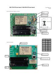
The WA-TX-01 (transmitter) and WA-<br />
RX-01 (receiver) modules represent a<br />
novel concept in the wireless transmission<br />
of audio signals. Thanks to low<br />
power consumption, the technology<br />
lends itself to a wide range of audio<br />
applications. The transmitter and the<br />
receiver include components such as<br />
SAW filters, SAW resonators and noise<br />
reduction ICs.<br />
These key components allow the<br />
development of small high-quality<br />
audio modules in accordance with<br />
European radio regulations and with<br />
EMC and R&TTE guidelines. This<br />
means that a wireless link can be<br />
added to an audio device without having<br />
to worry about a complicated,<br />
expensive and time-consuming certification<br />
process. The frequency channel<br />
used by each module is fixed, but there<br />
are four separate channels available in<br />
the band from 863 MHz to 865 MHz,<br />
and so multiple systems can coexist in<br />
the same location.<br />
Dynamic<br />
transmission<br />
The maximum sound<br />
pressure level (SPL) which<br />
can be tolerated by humans is<br />
140 dB SPL , which is measured relative<br />
to the minimum audible sound<br />
pressure level of 0 dB SPL = 20 µPa. In a<br />
quiet room the background noise level<br />
is about 20 dB SPL , and the sound pressure<br />
level of the human voice is around<br />
120 dB SPL . It can therefore be seen that<br />
the dynamic range required for a normal<br />
wireless audio transmission system<br />
is around 100 dB.<br />
If an audio frequency of 15 kHz is<br />
transmitted using analogue frequency<br />
modulation, the required bandwidth<br />
(BW) is given by:<br />
BW =<br />
2 (maximum frequency deviation +<br />
maximum modulation frequency) [Hz]<br />
Unfortunately any FM circuit must suffer<br />
from residual sideband noise originating<br />
in the PLL or crystal oscillator.<br />
As a rule of thumb, we can reckon with<br />
a residual noise, measured in terms of<br />
frequency shift, of around 50 Hz. For a<br />
dynamic range of 100 dB (i.e., a factor<br />
of 100 000), we therefore need an overall<br />
frequency deviation of 50 × 100 000<br />
= 5 MHz. As you might expect, this<br />
means that the required bandwidth is<br />
much greater than that available in<br />
this application. For comparison, FM<br />
radio transmissions make do with a<br />
0 dB<br />
-20 dB<br />
-40 dB<br />
-60 dB<br />
-80 dB<br />
-100 dB<br />
Transmitter<br />
input signal<br />
Compressor<br />
maximum deviation of 75 kHz in a<br />
bandwidth of 180 kHz (mono) or<br />
264 kHz (stereo plus traffic data).<br />
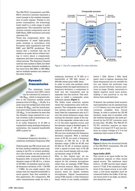
In order to solve this problem while<br />
keeping within the legal restrictions on<br />
frequency deviation, a compressor is<br />
built into the transmitter and an<br />
expander into the receiver. This technique<br />
is called a compander noise<br />
reduction system (Figure 1).<br />
The Dolby noise reduction system<br />
varies the compression ratio with frequency.<br />
The compander noise reduction<br />
system used here, on the other<br />
hand, fixes the compression ratio at 2:1<br />
over the entire frequency range, thus<br />
halving the dynamic range of the signal.<br />
In the expander, whose ratio is set<br />
to 1:2, the exact opposite occurs, and<br />
the dynamic range is doubled again. A<br />
dynamic range of 100 dB is thus<br />
reduced to 50 dB for transmission.<br />
We can now recalculate the frequency<br />
deviation required. With a residual<br />
noise of 50 Hz we need a frequency<br />
deviation of 500 Hz for a 20 dB<br />
dynamic range, 5 kHz for 40 dB, and<br />
20 kHz for 52 dB. A wireless system<br />
with a signal-to-noise ratio of 50 dB<br />
can carry sound signals with an original<br />
dynamic range of 100 dB.<br />
Why, in this ‘digital age’, do we<br />
employ analogue transmission techniques<br />
for the wireless microphone<br />
rather than, for example, PCM There<br />
are several reasons. Many countries<br />
have not allocated a dedicated frequency<br />
band for digital wireless<br />
microphones. Digital transmissions<br />
using PCM require a wide frequency<br />
band, which is not readily available<br />
Compander process<br />
Radio<br />
transmission<br />
∆ f limit level<br />
-10 dB<br />
-20 dB<br />
-30 dB<br />
-40 dB<br />
-50 dB<br />
-60 dB<br />
FM residual noise<br />
040402 - 13<br />
Figure 1. Use of a compander for noise reduction.<br />
Expander<br />
Receiver<br />
output signal<br />
FM residual noise<br />
below 1 GHz. Above 1 GHz ‘dead<br />
spots’ start to appear, meaning that<br />
these frequencies are not suitable for<br />
live use where the performer may<br />
move around between various positions<br />
on stage. Finally, conversion to<br />
digital requires much more power,<br />
making it less practical to run the<br />
device from small batteries.<br />
If desired, the modules (both receiver<br />
and transmitter) can be operated from<br />
a 1.5 V battery via a low-noise DC-DC<br />
converter available from <strong>Circuit</strong><br />
<strong>Design</strong>. In order to achieve the 100 dB<br />
dynamic range that is possible with<br />
the wireless microphone, the noise produced<br />
by the DC-DC converter muct<br />
be less than –60 dBm. The WA-DC-01<br />
DC-DC converter requires an input<br />
voltage of at least 0.9 V and can produce<br />
an output voltage of 3 V at the<br />
maximum load current of 50 mA.<br />
The transmitter<br />
0 dB<br />
-20 dB<br />
-40 dB<br />
-60 dB<br />
-80 dB<br />
-100 dB<br />
Figure 2 shows the functional blocks<br />
of the WA-TX-01 transmitter. We will<br />
look at each in turn.<br />
Input buffer (BUF)<br />
This circuit is an input buffer for the<br />
microphone capsule or other sound<br />
signal source. The maximum input<br />
level is –15 dBV and the input impedance<br />
is 7.5 kΩ. If the maximum output<br />
level of the signal source is not sufficient,<br />
a low-noise amplifier must be<br />
connected before the buffer. If the signal<br />
source level is too high, an attenuator<br />
should be used.<br />
2/2005 - elektor electronics 21