PDF:512KB - Circuit Design, Inc.
PDF:512KB - Circuit Design, Inc.
PDF:512KB - Circuit Design, Inc.

Create successful ePaper yourself
Turn your PDF publications into a flip-book with our unique Google optimized e-Paper software.
C3<br />
IC1<br />
T<br />
0<br />
MIC1<br />
+3V<br />
C2<br />
P1<br />
R1<br />
AF<br />
T<br />
C1<br />
JP1<br />
040402-1<br />
IC2<br />
040402-1<br />
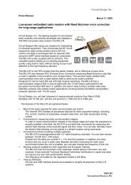
Figure 5. Two circuit boards make one radio link.<br />
COMPONENTS<br />
LIST<br />
Resistors:<br />
R1 = 2kΩ2<br />
R2,R8 = 560Ω*<br />
R3,R4 = 220kΩ<br />
R5 = 4kΩ7<br />
R6 = 47Ω<br />
R7 = 100kΩ<br />
P1,P2 = 10 kΩ preset<br />
Capacitors:<br />
C1,C6 = 4µF7 63V radial<br />
C2,C7 = 100nF<br />
C3,C5,C8 = 10µF 63V radial<br />
C4 = 470nF<br />
C7<br />
040402-1<br />
D2<br />
D1<br />
R2<br />
R8<br />
R6<br />
R7<br />
C4<br />
IC3<br />
C6<br />
R3<br />
R5<br />
R4<br />
C8<br />
P2<br />
K1<br />
C5<br />
+5V<br />
Semiconductors:<br />
D1 = LED, 3mm, green, low current<br />
D2 = LED, 3mm, red, low current<br />
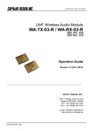
IC1 = WA-TX-01 (<strong>Circuit</strong> <strong>Design</strong>)<br />
IC2 = WA-RX-01A (<strong>Circuit</strong> <strong>Design</strong>)<br />
IC3 = TS921IN (or equivalent rail-to-railopamp)<br />
Miscellaneous:<br />
JP1 = 2-way pinheader with jumper<br />
(angled if necessary)<br />
K1 = 3.5-mm jack socket, PCB mount<br />
(e.g. Conrad Electronics # 732893)<br />
BT1 = battery holder for two 1.5V<br />
batteries<br />
MIC1 = electret microphone<br />
PCB, no. 040402-1, available from The<br />
PCBShop<br />
0<br />
with an asymmetric 10 V supply. A further<br />
advantage of the TS921 used here<br />
is its high output drive capability: it can<br />
directly drive headphones or even two<br />
32 Ω headphone transducers wired in<br />
parallel, although in this case C6 should<br />
be replaced by a 100 µF 10 V type. The<br />
47 Ω output resistor protects the opamp<br />
from the inductive load of a shielded<br />
cable and from short circuits. Trimmer<br />
potentiometer P2 allows the gain to be<br />
adjusted from unity (P2 at minimum<br />
resistance) to 10 dB (P2 at maximum<br />
resistance). C6 removes any DC component<br />
from the output and R7 ensures<br />
that there is always a load at the output.<br />
Since the opamp has asymmetrical<br />
supplies, a capacitor (C5) is also<br />
required in the feedback circuit. R3 and<br />
R4 set the operating point of the opamp<br />
at half the supply voltage. C7 and C8<br />
provide extra power supply decoupling.<br />
At higher supply voltages it is necessary<br />
to increase the current-limiting<br />
resistors for the low-current LEDs so<br />
that the current through them does not<br />
exceed about 2 mA.<br />
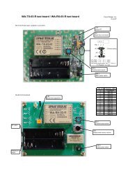
We have designed a two-part printed<br />
circuit board to accommodate the radio<br />
modules and the few external components<br />
(Figure 5). The layout is designed<br />
for optimum audio performance.<br />
The components should be fitted to the<br />
board, observing that the transmitter<br />
module can only be fitted to the copper<br />
side. An ordinary 3.5 mm jack socket<br />
provides the audio output.<br />
All that remains are the antennas. In<br />
principle a stiff piece of wire with<br />
length 1/4 λ (78 mm at 860 MHz) will<br />
do the job; more professional antennas<br />
can be found on the <strong>Circuit</strong> <strong>Design</strong><br />
website at http://www.cdt21.com/.<br />
(040402-1)<br />
24<br />
elektor electronics - 2/2005