Comfort Alert Diagnostics Copeland - Desco Energy
Comfort Alert Diagnostics Copeland - Desco Energy
Comfort Alert Diagnostics Copeland - Desco Energy

You also want an ePaper? Increase the reach of your titles
YUMPU automatically turns print PDFs into web optimized ePapers that Google loves.
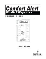
543-0032-00, 943-0032-00<br />
User’s Manual<br />
1
<strong>Comfort</strong> <strong>Alert</strong> <strong>Diagnostics</strong> – Faster Service And Improved Accuracy<br />
The <strong>Comfort</strong> <strong>Alert</strong> diagnostics module is a breakthrough innovation for troubleshooting<br />
heat pump and air conditioning system failures. The module installs easily in the electrical<br />
box of the outdoor unit near the compressor contactor. By monitoring and analyzing<br />
data from the <strong>Copeland</strong> Scroll ® compressor and the thermostat demand, the module<br />
can accurately detect the cause of electrical and system related failures without any<br />
sensors. A flashing LED indicator communicates the ALERT code and guides the service<br />
technician more quickly and accurately to the root cause of a problem.<br />
NOTE: This module does not provide safety protection! The <strong>Comfort</strong> <strong>Alert</strong> module<br />
is a monitoring device and cannot shut down the compressor directly.<br />
LED Description (Figure 1)<br />
POWER LED (Green): indicates voltage is present at<br />
the power connection of the module.<br />
ALERT LED (Yellow): communicates an abnormal system<br />
condition through a unique flash code. The ALERT LED<br />
will flash a number of times consecutively, pause and then<br />
repeat the process. The number of consecutive flashes,<br />
defined as the Flash Code, correlates to a particular<br />
abnormal condition. Detailed descriptions of specific<br />
ALERT Flash Codes are shown in two tables on pages 8<br />
and 9 of this manual.<br />
TRIP LED (Red): indicates there is a demand signal from<br />
the thermostat but no current to the compressor is detected<br />
by the module. The TRIP LED typically indicates the<br />
compressor protector is open or may indicate<br />
missing supply power to the compressor.<br />
Product Specifications<br />
Operating Temperature: -40° to 150° F (-40° to 65° C)<br />
Storage Temperature: -40° to 175° F (-40° to 80° C)<br />
Power Supply Range: 18-30VAC, 48-62 Hz<br />
Power Requirement: 1.5 VA nominal<br />
UL Restrictions:<br />
Use only with Class 2 circuits.<br />
Figure 1<br />
UL File #SA8958<br />
This <strong>Comfort</strong> <strong>Alert</strong> module is designed only for single-phase systems with <strong>Copeland</strong><br />
scroll compressors that have internal overload protection. The software in this <strong>Comfort</strong><br />
<strong>Alert</strong> module has been optimized for single stage scroll systems.<br />
2
Module Dimensions (Figure 2):<br />
A. 1.85 in (47 mm) D. 4.40 in (112mm)<br />
B. 2.44 in (62 mm) E. 2.44 in (62 mm)<br />
C. 1.46 in (37 mm)<br />
Figure 2<br />
WARNING<br />
Hazardous voltage inside air conditioning system.<br />
Disconnect power before installing or servicing module.<br />
Module must be installed and serviced only by qualified<br />
personnel.<br />
Hardware Installation<br />
Four #8 or #10 self drilling or sheet metal screws, at least ½” length, are required for<br />
installation of the <strong>Comfort</strong> <strong>Alert</strong> module. The maximum screw torque is 20 in.-lbs. Locate<br />
the <strong>Comfort</strong> <strong>Alert</strong> module near the compressor contactor (wire routing for compressor<br />
run, common and start wires will be easier in this position). Mount the <strong>Comfort</strong> <strong>Alert</strong><br />
module so all LEDs are visible from a comfortable viewing position. The module will<br />
operate in any mounting orientation. For ease of reading labels, the module should be<br />
oriented so that the green POWER LED is at the top.<br />
3
Compressor Wire Routing (Figure 3)<br />
The scroll compressor’s run (R), common (C) and start (S) wires are routed through the<br />
holes in the <strong>Comfort</strong> <strong>Alert</strong> module marked “R,” “C” and “S.” The common (C) wire need<br />
not be routed through the module for it to operate properly.<br />
24VAC Power Wiring<br />
The <strong>Comfort</strong> <strong>Alert</strong> module requires<br />
a constant nominal 24VAC power<br />
supply. The wiring to the module’s<br />
R and C terminals must be directly<br />
from the indoor unit or thermostat.<br />
The module cannot be powered by<br />
the C terminal on a defrost board<br />
or other control board without<br />
experiencing nuisance alerts.<br />
Refer to Figure 5.<br />
Figure 3<br />
When constant 24VAC (R wire)<br />
is not present in the outdoor unit,<br />
use one of the spare wires in the<br />
thermostat cable to bring power to<br />
the module. Connect the other end<br />
of the spare wire to R at the indoor<br />
unit or thermostat. Refer to wiring<br />
schematic in Figure 4 and 5.<br />
Thermostat Demand Wiring<br />
The <strong>Comfort</strong> <strong>Alert</strong> module requires a thermostat demand signal to operate properly. The<br />
thermostat demand signal input, labeled Y on the module, should always be connected<br />
to the compressor contactor coil so that when the coil is energized, the demand signal<br />
input is 24VAC. When the coil is not energized, the demand signal input should be less<br />
than 0.5VAC.<br />
NOTE: Factory installed modules may have different thermostat demand signal<br />
wiring. Follow manufacturer’s wiring instructions when replacing module.<br />
NOTE: After the thermostat demand signal is connected, verify Y is phased<br />
properly with C by measuring 24VAC across Y and C when demand is present.<br />
4
CC<br />
HPCO<br />
HTCO<br />
LPCO<br />
<strong>Comfort</strong> <strong>Alert</strong><br />
<strong>Diagnostics</strong><br />
Module<br />
543-0032-00<br />
Y<br />
L<br />
R<br />
C<br />
Indoor Unit<br />
Terminal Block<br />
C R L Y1<br />
C R L Y1<br />
Single Stage Indoor Thermostat<br />
Figure 4 Air Conditioning Schematic<br />
Schematic Abbrevation Descriptions<br />
HTCO High Temperature Cut Out Switch CC Compressor Contactor<br />
HPCO High Pressure Cut Out Switch LPCO Low Pressure Cut Out Switch<br />
CC<br />
HPCO<br />
HTCO<br />
LPCO<br />
<strong>Comfort</strong> <strong>Alert</strong><br />
<strong>Diagnostics</strong><br />
Module<br />
543-0032-00<br />
Y<br />
L<br />
R<br />
C<br />
Defrost<br />
Board<br />
Indoor Unit<br />
Terminal Block<br />
C R L Y1<br />
C R L Y1<br />
Single Stage Indoor Thermostat<br />
Figure 5 Heat Pump Schematic<br />
5
L Terminal Wiring<br />
The L connection is used to communicate <strong>Alert</strong> codes to compatible White-Rodgers<br />
thermostats. The L terminal of the thermostat should be connected directly to the <strong>Comfort</strong><br />
<strong>Alert</strong> L terminal.<br />
On select White-Rodgers thermostats, an icon on the thermostat display will flash at<br />
the same rate as the <strong>Comfort</strong> <strong>Alert</strong> yellow <strong>Alert</strong> LED. An advanced option on these<br />
thermostats is to lock out the compressor when certain <strong>Alert</strong> codes are detected indicating<br />
impending compressor damage. Refer to White-Rodgers thermostat manuals for more<br />
information.<br />
6
Interpreting The Diagnostic LEDs<br />
When an abnormal system condition occurs, the <strong>Comfort</strong> <strong>Alert</strong> module displays the<br />
appropriate ALERT and/or TRIP LED. The yellow ALERT LED will flash a number of<br />
times consecutively, pause and then repeat the process. To identify a Flash Code<br />
number, count the number of consecutive flashes. Every time the module powers<br />
up, the last ALERT Flash Code that occurred prior to shut down is displayed for one<br />
minute.<br />
Installation Verification<br />
To verify the installation of <strong>Comfort</strong> <strong>Alert</strong> is correct, two functional tests can be performed.<br />
Disconnect power from the compressor and force a thermostat call for cooling. The red<br />
Trip LED should turn on indicating a compressor trip as long as 24VAC is measured at<br />
the Y terminal. If the red LED does not function as described, refer to Table 1 to verify<br />
the wiring.<br />
Disconnect power from the compressor and 24VAC from <strong>Comfort</strong> <strong>Alert</strong>. Remove the<br />
wire from the Y terminal of <strong>Comfort</strong> <strong>Alert</strong>, reapply 24VAC power to <strong>Comfort</strong> <strong>Alert</strong> and<br />
reconnect power to the compressor. Force a thermostat call for cooling and when the<br />
Compressor starts to run, the yellow <strong>Alert</strong> LED will begin flashing a Code 8 indicating<br />
a Welded Contactor. Disconnect power from the compressor and 24VAC from <strong>Comfort</strong><br />
<strong>Alert</strong>. While <strong>Comfort</strong> <strong>Alert</strong> is off, reattach the wire to the Y terminal. Reapply power to<br />
compressor and 24VAC to <strong>Comfort</strong> <strong>Alert</strong>, the yellow <strong>Alert</strong> LED will flash the previous<br />
code 8 for 1 minute and then turn off. If the yellow LED does not function as described,<br />
refer to Table 1 to verify the wiring.<br />
Troubleshooting The Installation<br />
Depending on the system configuration, some ALERT Flash codes may not be active.<br />
The presence of safety switches affects how the system alerts are displayed by this<br />
module. Refer to Figures 4 & 5 for safety switch wiring.<br />
Resetting <strong>Alert</strong> Codes<br />
<strong>Alert</strong> codes can be reset manually and automatically. The manual method to reset an <strong>Alert</strong><br />
code is to cycle the power to <strong>Comfort</strong> <strong>Alert</strong> off and on. For automatic reset, <strong>Comfort</strong> <strong>Alert</strong><br />
continues to monitor the compressor and system after an <strong>Alert</strong> is detected. If conditions<br />
return to normal, the <strong>Alert</strong> code is turned off automatically.<br />
<strong>Comfort</strong> <strong>Alert</strong> Part Numbers<br />
OEM P/N Service P/N <strong>Copeland</strong> Scroll Compressor Application<br />
543-0010-00 943-0010-00 Single Stage Air Conditioning<br />
543-0012-00 943-0012-00 All Heat Pump and Two Stage A/C<br />
543-0032-00 943-0032-00 Single Stage A/C & Heat Pump<br />
543-0033-00 943-0033-00 Two Stage A/C & Heat Pump<br />
7
Status LED Status LED Description Status LED Troubleshooting Information<br />
Green “POWER” Module has power Supply voltage is present at module terminals<br />
Red “TRIP”<br />
Yellow “ALERT”<br />
Flash Code 1<br />
Yellow “ALERT”<br />
Flash Code 2<br />
Thermostat demand signal Y is<br />
present, but the compressor is<br />
not running<br />
Long Run Time Compressor<br />
is running extremely long run<br />
cycles<br />
System Pressure Trip<br />
Discharge or suction<br />
pressure out of limits or<br />
compressor overloaded<br />
1.Compressor protector is open<br />
•Check for high head pressure<br />
•Check compressor supply voltage<br />
2.Outdoor unit power disconnect is open<br />
3.Compressor circuit breaker or fuse(s) is open<br />
4.Broken wire or connector is not making contact<br />
5.Low pressure switch open if present in system<br />
6.Compressor contactor has failed open<br />
1.Low refrigerant charge<br />
2.Evaporator blower is not running<br />
•Check blower relay coil and contacts<br />
•Check blower motor capacitor<br />
•Check blower motor for failure or blockage<br />
•Check evaporator blower wiring and connectors<br />
•Check indoor blower control board<br />
•Check thermostat wiring for open circuit<br />
3.Evaporator coil is frozen<br />
•Check for low suction pressure<br />
•Check for excessively low thermostat setting<br />
•Check evaporator airflow (coil blockages or return air filter)<br />
•Check ductwork or registers for blockage<br />
4.Faulty metering device<br />
•Check TXV bulb installation (size, location and contact)<br />
•Check if TXV/fixed orifice is stuck closed or defective<br />
5. Condenser coil is dirty<br />
6. Liquid line restriction (filter drier blocked if present in system)<br />
8. Thermostat is malfunctioning<br />
•Check thermostat sub-base or wiring for short circuit<br />
•Check thermostat installation (location, level)<br />
9.<strong>Comfort</strong> <strong>Alert</strong> failure<br />
1. High head pressure<br />
•Check high pressure switch if present in system<br />
•Check if system is overcharged with refrigerant<br />
•Check for non-condensable in system<br />
2. Condenser coil poor air circulation (dirty, blocked, damaged)<br />
3.Condenser fan is not running<br />
•Check fan capacitor<br />
•Check fan wiring and connectors<br />
•Check fan motor for failure or blockage<br />
4.Return air duct has substantial leakage<br />
5.If low pressure switch present in system, check Flash<br />
Code 1 information<br />
8
Status LED Status LED Description Status LED Troubleshooting Information<br />
Yellow “ALERT”<br />
Flash Code 3<br />
Short Cycling<br />
Compressor is running<br />
only briefly<br />
1. Thermostat demand signal is intermittent<br />
2. Time delay relay or control board defective<br />
3. If high pressure switch present go to Flash Code 2 information<br />
4. If low pressure switch present go to Flash Code 1 information<br />
Yellow “ALERT”<br />
Flash Code 4<br />
Yellow “ALERT”<br />
Flash Code 5<br />
Yellow “ALERT”<br />
Flash Code 6<br />
Yellow “ALERT”<br />
Flash Code 7<br />
Yellow “ALERT”<br />
Flash Code 8<br />
Yellow “ALERT”<br />
Flash Code 9<br />
Locked Rotor<br />
Open Circuit<br />
Open Start Circuit<br />
Current only in run circuit<br />
Open Run Circuit<br />
Current only in start circuit<br />
Welded Contactor<br />
Compressor always runs<br />
Low Voltage<br />
Control circuit < 17VAC<br />
1.Run capacitor has failed<br />
2.Low line voltage (contact utility if voltage at disconnect is low)<br />
•Check wiring connections<br />
3.Excessive liquid refrigerant in compressor<br />
4.Compressor bearings are seized<br />
•Measure compressor oil level<br />
1.Outdoor unit power disconnect is open<br />
2.Compressor circuit breaker or fuse(s) is open<br />
3.Compressor contactor has failed open<br />
•Check compressor contactor wiring and connectors<br />
•Check for compressor contactor failure (burned, pitted or open)<br />
•Check wiring and connectors between supply and compressor<br />
•Check for low pilot voltage at compressor contactor coil<br />
4.High pressure switch is open and requires manual reset<br />
5.Open circuit in compressor supply wiring or connections<br />
6.Unusually long compressor protector reset time due to<br />
extreme ambient temperature<br />
7.Compressor windings are damaged<br />
•Check compressor motor winding resistance<br />
1.Run capacitor has failed<br />
2.Open circuit in compressor start wiring or connections<br />
•Check wiring and connectors between supply and the<br />
compressor “S” terminal<br />
3.Compressor start winding is damaged<br />
•Check compressor motor winding resistance<br />
1.Open circuit in compressor run wiring or connections<br />
•Check wiring and connectors between supply and the<br />
compressor “R” terminal<br />
2.Compressor run winding is damaged<br />
•Check compressor motor winding resistance<br />
1.Compressor contactor has failed closed<br />
2.Thermostat demand signal not connected to module<br />
1.Control circuit transformer is overloaded<br />
2.Low line voltage (contact utility if voltage at disconnect is low)<br />
•Check wiring connections<br />
Flash Code number corresponds to a number of LED flashes, followed by a pause and then repeated.<br />
TRIP and ALERT LEDs flashing at same time means control circuit voltage is too low for operation.<br />
9
NOTE: The correct <strong>Comfort</strong> <strong>Alert</strong> model must be used for the application (refer<br />
to the Product Specification section on pages 2 and 3). If the wrong model is<br />
installed, the ALERT Flash Codes for system faults will function incorrectly: the<br />
<strong>Comfort</strong> <strong>Alert</strong> module may indicate system faults that are not present or fail to<br />
indicate system faults that are present.<br />
NOTE: Miswiring the <strong>Comfort</strong> <strong>Alert</strong> module will cause false LED codes. Table 1<br />
describes LED operation when the module is miswired and what troubleshooting<br />
action is required to correct the problem.<br />
Miswired Module Indication Recommended Troubleshooting Action<br />
Green LED is not on,<br />
Determine if both R and C module terminals are<br />
module does not power up connected. Verify voltage is present at module’s R and<br />
C terminals. Review 24VAC Power Wiring (page 4) for<br />
R and C wiring.<br />
Green LED intermittent, Determine if R and Y terminals are wired in reverse.<br />
module powers up only<br />
Verify module’s R and C terminals have a constant<br />
when compressor runs<br />
source. Review 24VAC Power Wiring (page 4) for R<br />
and C wiring.<br />
TRIP LED is on but system Verify Y terminal is connected to 24VAC at contactor<br />
and compressor check OK coil. Verify voltage at contactor coil falls below 0.5VAC<br />
when off. Verify 24VAC is present across Y and C when<br />
thermostat demand signal is present. If not, R and C are<br />
reverse wired.<br />
TRIP LED and ALERT LED Verify R and C terminals are supplied with 19-28VAC.<br />
flashing together<br />
ALERT Flash Code 3<br />
Verify Y terminal is connected to 24VAC at contactor coil.<br />
(Compressor Short Cycling) Verify voltage at contactor coil falls below 0.5VAC when<br />
displayed incorrectly<br />
off.<br />
ALERT Flash Code 5, 6 or 7 Check that compressor run and start wires are through<br />
(Open Circuit, Open Start Circuit module’s current sensing holes. Verify Y terminal is<br />
or Open Run Circuit) displayed connected to 24VAC at contactor coil. Verify voltage at<br />
incorrectly<br />
contactor coil falls below 0.5VAC when off.<br />
ALERT Flash Code 6 (Open Check that compressor run and start wires are routed<br />
Start Circuit) displayed for Code 7 through the correct module sensing holes.<br />
(Open Run Circuit) or vice versa<br />
ALERT Flash Code 8<br />
Determine if module’s Y terminal is connected. Verify Y<br />
(Welded Contactor)<br />
terminal is connected to 24VAC at contactor coil. Verify<br />
displayed incorrectly<br />
24VAC is present across Y and C when thermostat<br />
demand signal is present. If not, R and C are reverse<br />
wired. Verify voltage at contactor coil falls below 0.5VAC<br />
when off. ReviewThermostat Demand Wiring (page 4) for<br />
Y and C wiring.<br />
Table 1<br />
10
Warranty Information<br />
<strong>Copeland</strong> Corporation warrants its enclosed diagnostic module to be free from defects in<br />
materials and workmanship under normal use for a period of one year from the date of<br />
purchase or twenty months from manufacture whichever comes first. During this period,<br />
<strong>Copeland</strong> Corporation will replace any defective diagnostic module without charge.<br />
This warranty is valid for the original purchaser from the date of initial purchase and is<br />
not transferable. Keep the original sales receipt. Proof of purchase is required to obtain<br />
warranty replacement. Dealers or service centers selling this product do not have the<br />
right to alter, modify or in any way change the terms and conditions of this warranty.<br />
This warranty does not cover normal wear of parts or damage resulting from any of the<br />
following: negligent use or misuse of the product, use on improper voltage or current,<br />
use contrary to the operating instructions, disassembly, repair or alteration by anyone<br />
other than <strong>Copeland</strong> Corporation. Further, the warranty does not cover acts of God,<br />
such as fire, flood, hurricanes and tornadoes.<br />
COPELAND CORPORATION MAKES NO IMPLIED WARRANTIES OF<br />
MERCHANTABILITY OR FITNESS FOR PARTICULAR PURPOSE WITH RESPECT<br />
TO THE COMFORT ALERT MODULE.<br />
<strong>Copeland</strong> Corporation shall not be liable for any incidental or consequential damages<br />
caused by the breach of any express or implied warranty. Some states, provinces,<br />
or jurisdictions do not allow the exclusion or limitation of incidental or consequential<br />
damages or limitations on how long an implied warranty lasts, so the above limitations<br />
or exclusions may not apply to you. This warranty gives you specific legal rights, and<br />
you may also have other rights that vary from state to state, or province to province.<br />
Units under warranty and in need of repair should be returned to an authorized wholesaler<br />
or original equipment manufacturer.<br />
11
Patent 6, 615, 594 and Additional Patents Pending<br />
Form No. 2005ECT-25 Issued 3/05<br />
Emerson Climate Technologies is a service mark and a trademark<br />
of Emerson Electric Co. <strong>Comfort</strong> <strong>Alert</strong> is a trademark of <strong>Copeland</strong><br />
Corporation. Printed in the U.S.A. © 2005 <strong>Copeland</strong> Corporation.<br />
12