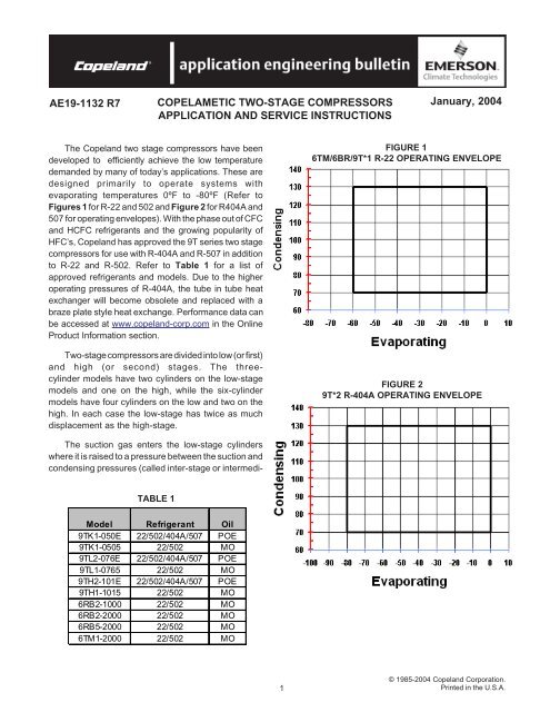
COPELAMETIC TWO-STAGE COMPRESSORS ... - Desco Energy
COPELAMETIC TWO-STAGE COMPRESSORS ... - Desco Energy
COPELAMETIC TWO-STAGE COMPRESSORS ... - Desco Energy
- No tags were found...

You also want an ePaper? Increase the reach of your titles
YUMPU automatically turns print PDFs into web optimized ePapers that Google loves.
AE19-1132TABLE 2INTER-<strong>STAGE</strong> PRESSURE R-22(<strong>TWO</strong>-<strong>STAGE</strong> 2/1 RATIO)TABLE 3INTER-<strong>STAGE</strong> PRESSURE R-502(<strong>TWO</strong>-<strong>STAGE</strong> 2/1 RATIO)TABLE 4Inner Stage Pressure R-404A W/ SubcoolerSuctionPressureHead Pressure (PSIG)200 230 270 300 35016.0 103.8 107.2 113.4 119.1 123.814.0 97.4 100.3 105.2 110.3 118.112.0 93.8 98.8 102.8 110.9 113.910.0 88.8 92.7 98.4 103.0 109.08.0 83.8 87.4 94.4 98.4 105.76.0 72.1 75.9 90.5 94.5 101.34.0 70.2 74.5 79.7 80.2 96.62.0 71.5 73.2 78.4 83.0 88.50.0 68.0 70.6 73.8 77.8 83.02" 60.9 64.1 68.2 70.7 75.84" 56.0 55.8 61.3 62.9 64.76" 50.7 51.7 53.9 55.6 57.48" 44.2 45.0 45.9 47.0 49.53© 1985-2004 Copeland Corporation.Printed in the U.S.A.
AE19-1132SUCTION LINE AND ACCUMULATORSTo prevent damage to these compressorscaused by slugging with liquid refrigerant and/oroil, adequate suction line accumulators (designedto prevent oil trapping) are mandatory on anysystem prone to return slugs of liquid or oil tothe compressor.If the suction vapor returning to the accumulatoris 5°F or below, it may be necessary to heat theaccumulator in order to return oil to the compressor.Note: The suction line must be well insulated with atleast 1" insulation including the accumulator, filter andsuction line vibrasorber if used.SUCTION LINE FILTERSSuction line filters should be installed toprevent minute particles of scale, flux, dirt, chipsof copper, etc., From entering the compressor.Care should be taken in their selection to preventexcessive pressure drop.LIQUID SIGHT GLASSESA liquid sight glass should be installed in theliquid line just ahead of the desuperheatingexpansion valve to provide a positive check forshortage of liquid.When a liquid sub-cooler is used the regularliquid line sight glass (additional to the one aheadof the desuperheating expansion valve) should beinstalled between the receiver and sub-cooler. Ifinstalled beyond the sub-cooler it will not bedependable as it will not show bubbles even whenthe system is short of gas.CRANKCASE PRESSURE REGULATING VALVESWith low voltage conditions the motors oftwo-stage compressors can be overloaded, andprotector tripping can be expected if the saturatedsuction temperature at the compressor inletexceeds the following limits for more than 3 or 4minutes.Low temperature compressors 0°F.Extra-low temperature compressors -30°F.The suction pressure on some systems can belimited to a satisfactory point by the size andtype of evaporator used or by the use of pressurelimiting expansion valves. Others will requirecrankcase pressure regulating valves. In selecting aregulating valve, limit the pressure drop to 2°F.(equivalent) maximum at normal operatingconditions.DESUPERHEATING EXPANSION VALVESOn all Copelametic two-stage compressors,liquid refrigerant is metered into the inter-stagemanifold by means of an expansion valve toreduce the superheat of the discharge gas fromthe low-stage cylinder. The expansion valvescurrently supplied as original equipment withCopelametic two-stage compressors are of thenon-adjustable superheat type.If the expansion valve becomes clogged or forother reasons fails to function properly, theliquid line solenoid and strainer should bechecked for obstructions and cleaned, and thevalve should be thoroughly washed out. If cleaningfails to restore satisfactory performance, thevalve must be replaced.In the event the proper Copeland replacementvalve is not available from the local Copelandwholesaler’s stock, standard field replacementvalves with adjustable superheat which have beenapproved by Copeland may be used.Normally it will be necessary to change thefactory setting of the adjustable superheat typeof valve to obtain proper performance. The valveshould be adjusted to obtain a temperature difference(superheat) of 15°F. to 30°F. between thetemperature of the manifold (at the bulb) andthe saturated temperature of the refrigerant atinter-stage pressure.© 1985-2004 Copeland Corporation.Printed in the U.S.A.4
AE19-1132Example - Using R-22 With Inter-Stage Pressure Of31 psig.Desired Superheat Limits:15°F. 30°F.R-22, 31 Psig Saturation Temperature: 8°F. 8°F.Desired Manifold Temperature Limits:23°F. 38°F.The desuperheating expansion valve should beadjusted to maintain a manifold temperature atthe bulb between 23°F. and 38°F.The superheat can be raised by turning thesuperheat adjustment stem clockwise, and can belowered by turning the stem counterclockwise.Because the characteristics of R-502 and R-404are such that it has less temperature rise during compression, tests have proven that for this applicationthe same expansion valve may be used for eitherR-22, R-502, and R-404A with satisfactory results.Note: Care should be taken in connecting theliquid supply line for the desuperheating expansionvalve. It should be not smaller than 3/8"O.D. And should be installed at the bottom of ahorizontal line, to insure a constant supply ofliquid at all times. This line should never beconnected to the top of a horizontal line becausevapor only will be picked up when the line isshort of liquid. Connection to a vertical line oflow velocity will be satisfactory.TABLE 5DESUPERHEATING EXPANSION VALVESField Replacements for CopelameticTwo-Stage CompressorsNon-AdjustableAdjustableCopelametic Copeland Sporlan Sporlan CopelandModel No. Part No. Part No. Part No. Part No.9TK 510-0144-00 IV-2-Z CV-2-Z 2 Turns In9TH, 9TL 510-0144-02 IV-3-Z CV-3-Z 2 Turns In6RB 510-0144-03 NCV-4-Z CV-5-Z 1 1/4Turns In6TM 510-0144-04 NCV-5-C CV-5-Z 1 1/4Turns InDEFROST CYCLEWith electric defrost, the compressor is notrunning during the defrost cycle, so no specialprecautions other than those normally requiredwith single stage systems are necessary.However, motor cooling on two-stage compressorsis dependent on an adequate feed of liquidrefrigerant from the desuperheating expansionvalve. If a hot gas defrost system is used, it isimperative that a solid head of liquid is maintainedat the desuperheating expansion valve atall times. Since hot gas defrost systems varywidely in design, it is not possible to make ageneral statement as to what special controls maybe required. Most manufacturers have thoroughlypretested their systems, but on field installations,restrictor valves to maintain head pressure, additionalrefrigerant charge, or other special controlsmay be necessary.<strong>TWO</strong>-<strong>STAGE</strong> COMPRESSOR PULSATIONAll reciprocating compressors create pulsationin the discharge gas line. Under normal operatingconditions, such pulsations are not of sufficientforce to cause any problems. The magnitude ofthe pulsation increases with a decrease in thenumber of cylinders pumping into a commondischarge chamber, and with increasing volumeand density of the gas pumped.Two-stage compressors handle gas of highdensity in the second or high stage. On the 9Tmodel compressors, only one cylinder is discharginginto the compressor discharge line, and on the6R model compressors, only two cylinders arepumping into the discharge line. Because of theseconditions, pulsation on two-stage compressorsmay be more pronounced than on single-stagecompressors.Normally these pulsations are not a problem.Occasionally, however, a combination of operatingconditions, mounting, and piping arrangementmay result in a resonant condition, which tendsto magnify the pulsation and cause vibration. Tosolve this problem, discharge muffler plates have5© 1985-2004 Copeland Corporation.Printed in the U.S.A.
AE19-1132been developed for the 9T and 6R two-stagecompressors. The muffler plate fits between thedischarge service valve and the compressor body.The muffler plate will effectively dampenpulsation and reduce vibration. It is now beinginstalled as standard equipment on all newtwo-stage compressors. If pulsation is a problemon existing equipment, it is recommended thatdischarge plates be installed. These are availablefrom your Copeland wholesaler under partnumbers shown below in Table 6.If the piping size and connections on a particularunit are such that resonance does occur, andthe muffler plate does not dampen it sufficiently,it may be necessary to bolt the compressor to itsmounting base with rubber vibration eliminatingmounting pads in order to change the vibrationfrequency.VALVE PLATES AND GASKETSValve plates on some models are the same asused on equivalent single-stage models but thehead gaskets are different. Always match thehead gasket with the head to be sure there is agasket section to match each partition in thehead. Incorrect gaskets cause leakage betweenstages.WARNING - DANGERDo not operate a service replacement two-stagecompressor without first installing the externalinter-stage manifold. There is no provisioninternally for escape of the high pressure gasfrom the low-stage cylinders, and without theexternal manifold dangerous pressures can becreated which could result in possible injury tothe operator.TABLE 6Copeland Part Number Description Application Data003-0107-00 Muffler Pate For all 9T Compressors003-0383-00 Muffler Pate For all 6RB and 6TM Compressors020-0012-09 Gasket (2 required) 1" hole size, 2 3/4" Centers027-0115-00 Upper Rubber Vibration Mount (4 required) 11/16" hole027-0114-00 Lower Rubber Vibration Mount (4 required) 11/16" holeComp.ModelValve Plate andGasket KitsNo.Part No.Req.TABLE 7Body-to-valvePlate GasketNo.Part No.Req.Valve Plate Head-To-Head GasketLow StageNo.Part No. Req.High StageNo.Part No. Req.9TK 998-0061-36 1 020-0128-01 1 020-0270-00 1 Same9TL 998-0061-36 1 020-0128-00 1 020-0270-00 1 Same9TH 998-0061-36 1 020-0128-04 1 020-0270-00 1 Same6RB26RB5998-0061-52 3 020-0626-00 3 020-0631-00 2 020-0630-00 16TM 998-0061-49 3 020-0433-00 3 020-0450-00 2 020-0441-00 1© 1985-2004 Copeland Corporation.Printed in the U.S.A.6
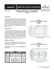
AE19-1132FIGURE 39T*2 WITH BRAZEPLATE SUBCOOLERFIGURE 49T PORT INDENTIFICATION7© 1985-2004 Copeland Corporation.Printed in the U.S.A.
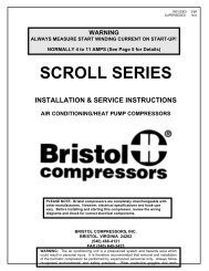
AE19-1132FIGURE 5SYSTEM WITH 3-CYLINDER COMPRESSOR (WITH LIQUID SUB-COOLER)FIGURE 6SYSTEM WITH 6-CYLINDER COMPRESSOR (WITH LIQUID SUB-COOLER)© 1985-2004 Copeland Corporation.Printed in the U.S.A.8
AE19-1132FIGURE 7SYSTEM WITH 3-CYLINDER COMPRESSOR (WITH INNER-TUBE LIQUID SUB-COOLER)FIGURE 8SYSTEM WITH 6-CYLINDER COMPRESSOR (WITH INNER-TUBE LIQUID SUB-COOLER)9© 1985-2004 Copeland Corporation.Printed in the U.S.A.
AE19-1132© 1985-2004 Copeland Corporation.Printed in the U.S.A.10
AE19-1132ServiceNo unusual service should be required on a well installed two-stage system. The electricalequipment is identical to single-stage compressors and requires no special comment.If a valve plate is suspected of being defective, it can easily be checked by observing the head,suction and inter-stage pressures. If the inter-stage pressure does not correspond within 7 lbs. to thatshown in tables 1 and 2, a malfunction is indicated.The Following Service Chart Will Assist In Diagnosis Of Other Possible Troubles:Complaint Cause Correction1. Suction 1. Short of charge 1. Add chargepressure 2. Restriction in liquid line 2. Remove restriction (can be caused byabnormallyplugged drier)low 3. Excessive pressure drop in suction line 3. Increase line size or remove restriction4. Inoperative expansion valve 4. Replace valve5. Evaporator fan not running 5. Repair or replace6. Plugged or iced evaporator 6. Clean or defrost7. Discharge pressure too low 7. See complaint number 32. Suction 1. Inter-Stage pressure too low 1. See complaint number 6pressure 2. Inter-Stage pressure too high 2. See complaint number 5abnormally 3. Evaporator expansion valve bulb loose 3. Clamp properlyhigh 4. Evaporator expansion valve malfunction 4. Replace5. Discharge pressure too high 5. See complaint number 46. Wrong head gasket 6. Install correct gasket3. Discharge 1. Short of charge 1. Add chargepressure 2. Low ambient on air-cooled condenser 2. Install winter control, various types areabnormallyavailablelow 3. Water regulator valve set too low 3. Adjust water valve4. Discharge 1. Plugged condenser 1. Clean condenserpressure 2. Excessively high temperature air 2. Prevent air from recirculating andabnormally Entering air-cooled condenser assure adequate ventilationhigh 3. High temperature water entering 3. Check water supplycondenser4. Water valve set too high 4. Adjust5. Condenser fan not running 5. Repair or replace5. Inter-stage 1. Blown gasket (discharge to inter-stage) 1. Replacepressure 2. Malfunctioning or broken high-stage reeds 2. Replace valve plate assemblytoo high6. Inter-stage 1. Blown gasket (inter-stage too low) 1. Replace gasketpressure 2. Malfunctioning or broken low-stage reeds 2. Replace valve plate assemblytoo low 3. Wrong high-stage head gasket 3. Install correct gasket7. Compressor runs 1. Liquid not being fed to desuperheating 1. Add charge if needed; move line so thathot, trips ther- expansion valve liquid is fed from bottom of horizontalmal protectorsline. Check liquid filter or drier for restriction.when not draw- 2. Improper bulb location 2. Locate properlying excessive 3. Improper setting of adjustable type 3. See adjusting instructionscurrent, dischargeexpansion valvetemperature 4. Defective valve 4. Replace valveabove 270ºF 5. Plugged liquid screen, filter, or drier 5. Clean or replace8. Ice on 1. Bulb not clamped properly, improper location 1. Clamp properly, locate properlystator cover or 2. Improper setting of adjustable type expansion valve 2. See adjusting instructionscrankcase 3. Defective valve 3. Replace valve11© 1985-2004 Copeland Corporation.Printed in the U.S.A.