Scroll Compressor Application Guidelines - Desco Energy
Scroll Compressor Application Guidelines - Desco Energy
Scroll Compressor Application Guidelines - Desco Energy
- No tags were found...

You also want an ePaper? Increase the reach of your titles
YUMPU automatically turns print PDFs into web optimized ePapers that Google loves.
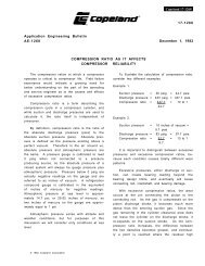
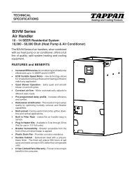
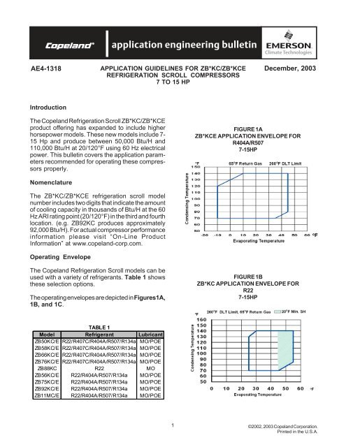
AE4-1318AE4-1318 APPLICATION GUIDELINES FOR ZB*KC/ZB*KCE December, 2003REFRIGERATION SCROLL COMPRESSORS7 TO 15 HPIntroductionThe Copeland Refrigeration <strong>Scroll</strong> ZB*KC/ZB*KCEproduct offering has expanded to include higherhorsepower models. These new models include 7-15 Hp and produce between 50,000 Btu/H and110,000 Btu/H at 20/120°F using 60 Hz electricalpower. This bulletin covers the application parametersrecommended for operating these compressorsproperly.FIGURE 1AZB*KCE APPLICATION ENVELOPE FORR404A/R5077-15HPNomenclatureThe ZB*KC/ZB*KCE refrigeration scroll modelnumber includes two digits that indicate the amountof cooling capacity in thousands of Btu/H at the 60Hz ARI rating point (20/120°F) in the third and fourthlocation. (e.g. ZB92KC produces approximately92,000 Btu/H). For actual compressor performanceinformation please visit “On-Line ProductInformation” at www.copeland-corp.com.Operating EnvelopeThe Copeland Refrigeration <strong>Scroll</strong> models can beused with a variety of refrigerants. Table 1 showsthese selection options.The operating envelopes are depicted in Figures1A,1B, and 1C.FIGURE 1BZB*KC APPLICATION ENVELOPE FORR227-15HPTABLE 1Model Refrigerant LubricantZB50KC/E R22/R407C/R404A/R507/R134a MO/POEZB58KC/E R22/R407C/R404A/R507/R134a MO/POEZB66KC/E R22/R407C/R404A/R507/R134a MO/POEZB76KC/E R22/R407C/R404A/R507/R134a MO/POEZB88KC R22 MOZB56KC/E R22/R404A/R507/R134a MO/POEZB75KC/E R22/R404A/R507/R134a MO/POEZB92KC/E R22/R404A/R507/R134a MO/POEZB11MC/E R22/R404A/R507/R134a MO/POE1©2002, 2003 Copeland Corporation.Printed in the U.S.A.
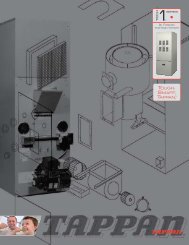
AE4-1318FIGURE 1CZB*KCE APPLICATION ENVELOPE FORR134A7-15HPTABLE 2CHARGE LIMITSModel FamilyZB50, 58, 66, 76, 88 KC/EZB56,75,92KC/E & ZB11MC/ECharg.Lmts.16 lbs17 lbsIf an accumulator must be used, an oil return orificesize in the range of 0.040 - 0.075 inches (1 - 1.9mm) is recommended. A large-area protectivescreen no finer than 30 x 30 mesh (0.6 mm openings)is required to protect this small orifice fromplugging with system debris. Tests have shownthat a small screen with a fine mesh can easilybecome plugged causing oil starvation to the compressorbearings.<strong>Compressor</strong> LubricationThe compressors can be used with different lubricantsdepending upon the refrigerant used. See<strong>Application</strong> Engineering Bulletin 17-1248 for a completelist of all Copeland approved lubricants.AccumulatorsDue to the inherent ability of scroll compressors tohandle liquid refrigerant in flooded start and defrostcycle operation conditions, accumulators may notbe required. An accumulator is required on singlecompressor systems when the charge limitationsexceed those values listed in Table 2. On systemswith defrost schemes or transient operations thatallow prolonged uncontrolled liquid return to thecompressor, an accumulator is required unless asuction header of sufficient volume to prevent liquidmigration to the compressors is used. Excessiveliquid floodback or repeated flooded starts will dilutethe oil in the compressor causing inadequatelubrication and bearing wear. Proper system designwill minimize liquid floodback, thereby ensuringmaximum compressor life.ScreensThe use of screens finer than 30 x 30 mesh (0.6mm openings) anywhere in the system is not recommended.Field experience has shown that finermesh screens used to protect thermal expansionvalves, capillary tubes, or accumulators can becometemporarily or permanently plugged withnormal system debris and block the flow of eitheroil or refrigerant to the compressor. Such blockagecan result in compressor failure.Crankcase HeaterCrankcase heaters are required on systems whenthe system charge exceeds the recommendedcharge limit. See Table 2.TABLE 3CRANKCASE HEATERSModel Part No. Volts Watts LeadsZB50, ZB58, 018-0047-00 120 90 48"ZB66, ZB76, 018-0047-01 240 90 48"ZB88 018-0047-02 480 90 48"018-0047-03 575 90 48"018-0036-00 240 70 26"018-0036-01 120 70 26"ZB56, 018-0036-02 480 70 26"ZB75, ZB92, 018-0036-03 575 60 26"ZB11M 018-0036-04 240 70 34"018-0036-05 480 70 34"018-0036-06 575 60 34"©2002, 2003 Copeland Corporation.Printed in the U.S.A.2
AE4-1318The listed crankcase heaters (Table 3) are intendedfor use only when there is limited access.The heaters are not equipped for use with electricalconduit. Where applicable, electric safety codesrequire heater lead protection, a crankcase heaterterminal box should be used. Recommended crankcaseheater terminal cover and box numbers arelisted in Table 3A. If there are any questions concerningthe application, contact the Copeland <strong>Application</strong>Engineering department.TABLE 3ACONDUIT READY HEATER BOX KITSModel NumberKit NumberZB50, ZB58, ZB66 998-7029-00ZB76, ZB88ZB56, ZB75 998-7015-00ZB92, ZB11MPressure ControlsBoth high and low pressure controls are requiredand the following are the minimum and maximumset points. Refer to Table 5 for proper settings.TABLE 5PRESSURE CONTROL SETTINGSModel Control R404A/R507 R134a R22Ty peZB50,ZB58, Low 17 psig min. 4 psig min. 37 psig min.ZB66, High 454 psig max. 263 psig max 381 psig maxZB76ZB88 Low N/A N/A 37 psig min.High N/A N/A 381 psig maxZB56,ZB75, Low 17 psig min. 4 psig min. 37 psig min.ZB92, High 454 psig max. 263 psig max 381 psig maxZB11MDischarge Line ThermostatThe thermostats have a cut out setting that willinsure discharge line temperatures remain belowthe 260°F maximum limit. It should be installedapproximately 7 inches from the discharge tubeoutlet. If a service valve is installed at the dischargetube, the thermostat should be located 5 inchesfrom the valve braze.Kits have been set up to include the thermostat,retainer, and installation instructions. Thesethermostats must be used with 7/8” O.D. dischargelines to ensure proper thermal transfer andtemperature control. They work with either 120 or240-volt control circuits, and are available with orwithout conduit ready connections. See Table 4 fora list of discharge line thermostat kit numbers.ModelDischargeT-StatT-Stat KitNumberConduitReadyZB50ZB58 Thermostat 998-0540-03 NoZB76 Required 998-7022-05 YesZB88ZB56ZB75ZB92ZB11MTABLE 4Internal Discharge TemperatureProtection ProvidedNo thermostat requiredIPR ValveThe 7.5 through 15 horsepower refrigeration scrollcompressors DO NOT have an internal high pressurerelief valve. To provide safe operation, a highpressure control set no higher than 445 psig mustbe used in all applications (reference Table 5).Motor ProtectionThe larger horsepower refrigeration scroll compressorshave either line break protection or theuse of sensors with an electronic module. The typeof protection is obtained from the protector code inthe model number. Table 6 lists the various modelsprotector number and the type of protection.TABLE 6MOTOR PROTECTIONModels with Line Break ProtectionZB50, ZB58, ZB66, ZB76, ZB88 No Module(note: electric code = TF*)Models with Electronic ModuleZB56, ZB75, ZB92, ZB11M P/N: 071-0547-01(note: electric code = TW*)3©2002, 2003 Copeland Corporation.Printed in the U.S.A.
AE4-1318For the electronic motor protection there are fivePTC (positive temperature coefficient) internalthermisters connected in series that react withavalanche resistance in the event of high temperatures.Four of the thermisters are used to sensemotor temperatures and the fifth is used as adischarge temperature sensor. The thermister circuitis connected to the protector module terminalsS1 and S2.When any thermister reaches a limiting value, themodule interrupts the control circuit and shuts off thecompressor. After the thermister has cooled sufficiently,the resistance will decrease, thus allowingthe module to reset. However, the module has a30-minute time delay before reset after a thermistertrip.For all other compressors, conventional internalline break motor protection is provided.Programmable Logic ControllerRequirementsIf the INT69SCY (071-0547-00) module is applied inconjunction with a Programmable Logic Controller,it is important that a minimum load is carriedthrough the M1-M2 control circuit contacts.The minimum required current through the modulerelay contacts needs to be greater than 100milliamps but not to exceed 5 amps. If thisminimum current is not maintained, this has adetrimental effect upon the long-term contact resistanceof the relay and may result in false compressortrips.PLC operated control circuits may not always providethis minimum current. In these cases modificationsto the PLC control circuit are required. Consultyour application engineering department for details.Phase ProtectionThe INT69-SCY module provides phase protectionfor the compressor. The module senses thecorrect phase sequence, phase loss and voltagesag for each leg (L1, L2 and L3) of the incomingpower supplied to the compressor. At installationthe three phases of the power supply must bewired in the correct 120° phase sequence. This willensure the compressor will start and operate in thecorrect clockwise direction.The INT69-SCY module trips (M1-M2 contacts open)when the module senses a phase loss. There is a5 minute time delay before the module attempts arestart. If all three phases are present, then themodule will reset (M1-M2 contacts will close) andFIGURE 2SCROLL WIRING SCHEMATICOMB OilLevel Control(Reference Table 4)Discharge LineRedBlackWhite(To Motor Overload Sensors)(To <strong>Compressor</strong> Terminal Block)©2002, 2003 Copeland Corporation.Printed in the U.S.A.4
AE4-1318the compressor will start and run. If not, the modulewill attempt a restart after another 5 minute timedelay. After 10 failed attempts to restart, themodule will lock-out (M1-M2 contacts will remainopen) and can only be reset by removing the powerfrom T1-T2 for a minimum of 5 seconds.The INT69SCY is intended to protect the compressor.The L1/L2/L3 and S1/S2 leads are pre-wiredon the compressor and are engineered to work inconjunction with the motor protector module. Themodule leads should not be moved or extendedbecause of the possibility of inducing electronicnoise into the INT69SCY, which could cause falsetrips of the module.Module and Sensor Functional CheckThe following field troubleshooting procedure canbe used to evaluate the solid state control circuit:Refer to Table 7 for a technical data summary.Module Voltage Supply Troubleshooting• Verify that all wire connectors are maintaininga good mechanical connection. Replace anyconnectors that are loose.• Measure the voltage across T1-T2 to ensureproper supply voltage.• Determine the control voltage by using avoltmeter and then measure the voltage acrossthe M1-M2 contacts:a) If the measured voltage is equal to the controlvolts then the M1-M2 contacts are open.b) If the measurement is less than 1 volt and thecompressor is not running, then the problemis external to the INT69-SCY module.c) If the voltage is greater than 1 volt but lessthan the control voltage, the module is faultyand should be replaced.Sensor Troubleshooting• Remove the leads from S1-S2, and then byusing an ohmmeter measure the resistance ofthe incoming leads.CAUTION: Use an Ohmmeter with amaximum of 9 VDC for checking – do notattempt to check continuity through thesensors with any other type of instrument.Any external voltage or current may causedamage requiring compressorreplacement.TABLE 7Copeland P/N 071-0520-07 071-0520-05 071-0547-01Manufacture P/N T.I. 30AA201E Kriwan 69SC-DV Kriwan 69SCYVoltage Supply 120V & 240VT1-T2 Module Power120V & 240V 120V & 240VFrequency 50Hz 60 Hz 50Hz 60 Hz 50Hz 60 HzM1-M2 Module Output ContactsMaximum Voltage N/A 250VAC 250VACMaximum Current 5 Amps 5 Amps 5 AmpsMinimum Current 100 milliamps 100 milliamps 100 milliampsRelay Output 2.5 A, 600 V 5 A, 300 VA 5 A, 300 VAPower Output < 5.5 VA < 3 VA < 3 VAS1-S2 Thermal ProtectionTrip Out Resistance N/A 4500Ω ± 20% 4500Ω ± 20%Reset Resistance N/A 2750Ω ± 20% 2750Ω ± 20%Reset Time 30 min ± 5 min. 30 min ± 5 min. 30 min ± 5 min.T1-T2 interrupt for minimum of T1-T2 interrupt for minimum of T1-T2 interrupt for minimum ofManual Reset5 sec5 sec5 secL1-L2-L3 Phase MonitoringPhase Sensor Non Phase Sensing Non Phase Sensing 3Phase Monitoring CircuitRating Non Phase Sensing Non Phase Sensing 3 AC 50/60Hz 120V to 632VTrip Delay Non Phase Sensing Non Phase Sensing5 min delay before restartattemptLockout Non Phase Sensing Non Phase Sensing After 10 module tripsReset for Lockout Non Phase Sensing Non Phase SensingT1-T2 interrupt for minimum of5 sec5©2002, 2003 Copeland Corporation.Printed in the U.S.A.
AE4-1318a) During normal operation, this resistancevalue should read less than 4500 ohms±20%.b) If the M1-M2 contacts are open, themeasured S1-S2 value is above 2750 ohms±20% and the compressor has been trippedless then 30 minutes then the module isfunctioning properly.• If the S1-S2 wire leads read less than 2750ohms ±20% and the M1-M2 contacts are open,reset the module by removing the power to T1-T2 for a minimum of 5 seconds.• Replace all wire leads and use a voltmeter toverify the M1-M2 contacts are closed.• If the M1-M2 contacts remain open and S1-S2are less than 2500 ohms, remove leads from theM1-M2 contacts and jumper together;CAUTION: <strong>Compressor</strong> should start at thistime. HOWEVER DO NOT LEAVE JUMPERIN PLACE FOR NORMAL SYSTEMOPERATIONS. THE JUMPER IS USEDFOR DIAGNOSTIC PURPOSES ONLY.• Go to <strong>Compressor</strong> Supply VoltageTroubleshooting.<strong>Compressor</strong> Voltage Supply Troubleshooting• Remove phase sensing leads from the modulefrom L1/L2/L3.• Use a voltmeter to measure the incoming 3phase voltage on L1/L2/L3. WARNING: L1/L2/L3 could be at a potential up to 600VAC.• Ensure proper voltage on each phase.• Remove power to the module for a minimum of5 seconds to reset and replace all wire leads.Re-energize the module. If the M1-M2 contactsare open with proper voltage to T1-T2, L1/L2/L3 and proper resistance to S1-S2 then themodule is faulty and should be replaced.Oil TypePolyol ester lubricant (POE) must be provided if theCopeland refrigeration scroll is used with HFCrefrigerants.Copeland refrigeration scrolls intended for use withR22 are supplied with mineral oil.Reference Table 7 for proper oil charge.TABLE 7COMPRESSOR OIL CHARGEModel Initial RechargeZB50 85 81ZB58 85 81ZB66 110 106ZB76 110 106ZB88 110 106ZB56 140 137ZB75 140 137ZB92 140 137ZB11M 140 137See <strong>Application</strong> Engineering Bulletin 17-1248 for acomplete list of all Copeland approved lubricants.Oil Management for Rack <strong>Application</strong>sCopeland Refrigeration <strong>Scroll</strong>s may be used onmultiple compressor parallel rack applications. Thisrequires the use of an oil management system tomaintain proper oil level in each compressor crankcase.The sight glass connection supplied canaccommodate the mounting of the oil controldevices.Unlike Semi-Hermetic compressors, <strong>Scroll</strong>s do nothave an oil pump with accompanying oil pressuresafety controls. Therefore, an external oil levelcontrol is required.The OMB Oil Level Management Control combinesthe functions of level control and timed compressorshut-off should the level not come back to normalwithin a set period of time. This device has beenfound to provide excellent performance in field testson <strong>Scroll</strong> compressors and is recommended forparallel system applications.Note: Due to issues that have been experiencedwith the Trax Oil level control, Copelandrecommends that OEM’s not use the Trax Oilon future new scroll compressor rack applications.We may consider denial of warranty forlubrication related failures when the Trax Oilcontrol is used on new systems in the future.Immediately after system start-up the oil reservoirlevel will fluctuate until equilibrium is reached. It is©2002, 2003 Copeland Corporation.Printed in the U.S.A.6
AE4-1318advisable to monitor the oil level during this time toassure sufficient oil is available. This will preventunnecessary trips of the oil control system.Note: If oil management problems are occuringplease refer to AE 17-1320 or contact theCopeland <strong>Application</strong> Engineering Department.Note: ZB50, 58, 66, 76, 88 are not approved forrack applications due to compressor limitations.<strong>Compressor</strong> Mounting<strong>Compressor</strong> mounting must be selected based onapplication. Consideration must be given to soundreduction tubing reliability. Some tubing geometry027-0115-00RUBBER PADFIGURE 37.5 - 15 HP RACK MOUNTING027-0280-00STEEL SPACER102-0119-00WASHERKIT #527-0158-00or “shock loops” may be required to reduce vibrationtransferred from the compressor to externaltubing.Mounting for Rack SystemsSpecially designed steel spacers and rubber isolatorpads are available for Copeland Refrigeration<strong>Scroll</strong> 7.5-15 HP scroll rack applications. Thismounting arrangement limits the compressors motionthereby minimizing potential problems of excessivetubing stress. Sufficient isolation is providedto prevent vibration from being transmitted tothe mounting structure. This mounting arrange-TABLE 8ModelRotalock SpudConnectionStubConnectionSuction Discharge Suction DischargeZB50 1-3/4 - 12 1-1/4 - 12 1-1/8" 7/8"ZB58 1-3/4 - 12 1-1/4 - 12 1-1/8" 7/8"ZB66 1-3/4 - 12 1-1/4 - 12 1-3/8" 7/8"ZB76 1-3/4 - 12 1-1/4 - 12 1-3/8" 7/8"ZB88 1-3/4 - 12 1-1/4 - 12 1-3/8" 7/8"ZB56 1-3/4 - 12 1-1/4 - 12 not offeredZB75 1-3/4 - 12 1-1/4 - 12 not offeredZB92 1-3/4 - 12 1-1/4 - 12 not offeredZB11M 2-1/4 - 12 1-3/4 -12 not offeredment is recommended for multiple compressorrack installations. See Figure 3 for a detail for thismounting system.Note: The use of standard soft grommets is notrecommended for Copeland Refrigeration <strong>Scroll</strong>rack installations. These “softer” mounts allow forexcessive movement that will result in tube breakageunless the entire system is properly designed.Connection FittingsThere are various connection fittings available forCopeland Refrigeration <strong>Scroll</strong> compressors. Thevarious options are shown in Table 8.Three Phase <strong>Scroll</strong> <strong>Compressor</strong>s – DirectionalDependents<strong>Scroll</strong> compressors are directional dependent; i.e.they will compress in one rotational direction only.Three phase <strong>Scroll</strong>s will rotate in either directiondepending on power phasing. Since there is a 50/50 chance of connected power being “backwards”,contractors should be warned of this. Appropriateinstructions or notices should be provided by theOEM. To eliminate the possibility of reverse rotationa Copeland Phase Control line monitor, P/N 085-0160-00, or other phase monitor is recommended.Verification of proper rotation can be made by observingthat the suction pressure drops and thedischarge pressure rises when the compressor isenergized. Additionally, if operated in reverse thecompressor is noisier and its current draw is substantiallyreduced compared to tabulated values.7©2002, 2003 Copeland Corporation.Printed in the U.S.A.
AE4-1318No time delay is required on three phase modelsto prevent reverse rotation due to brief powerinterruptions.Deep Vacuum OperationWARNING: Do not run a Copeland Refrigeration<strong>Scroll</strong> compressor in a deep vacuum.Failure to heed this advice can result in arcingof the Fusite pins and permanent damage tothe compressor.A low pressure control is required for protectionagainst deep vacuum operation. See PressureControl section for proper set points.<strong>Scroll</strong> compressors (as with any refrigerant compressor)should never be used to evacuate arefrigeration or air conditioning system. See <strong>Application</strong>Engineering Bulleting AE 24-1105 for propersystem evacuation procedures.Unbrazing System ComponentsIf the refrigerant charge is removed from a <strong>Scroll</strong>unit by bleeding the high side only, it is sometimespossible for the scrolls to seal, preventing pressureequalization through the compressor. Thismay leave the low side shell and suction line tubingpressurized. If a brazing torch is then applied to thelow side, the pressurized refrigerant and oil mixturecould ignite as it escapes and contacts thebrazing flame. It is important to check both the highand low sides with manifold gauges before unbrazingor in the case of assembly line repair, removerefrigerant from both the high and low sides. Instructionsshould be provided in appropriate productliterature and assembly (line repair) areas.Hi-Pot TestingCompliant <strong>Scroll</strong> compressors are configured withthe motor in the bottom of the shell. Unlike mostother hermetic compressors, the <strong>Scroll</strong> motor canbe immersed in refrigerant when liquid is present inthe shell. Hi-Pot test with liquid refrigerant in the shellcan show higher levels of current leakage due tohigher electrical conductivity of liquid refrigerant vs.refrigerant vapor and oil. This phenomenon canoccur with any compressor when the motor isimmersed in refrigerant and does not present anysafety issue. To lower the current leakage readingoperate the system for a brief period of time, redistributingthe refrigerant in a more normal configurationand test again.Note: The solid state electronic module componentsand internal sensors are delicate and canbe damaged by exposure to high voltage. Underno circumstances should a high potential test bemade at the sensor terminals or sensor leadsconnected to the module. Damage to the sensorsor module may result.©2002, 2003 Copeland Corporation.Printed in the U.S.A.8AE 1318 R1Revised 12/03Emerson is a service mark and a trademark of Emerson Electric Co.Copeland is a trademark of Copeland Corporation.© 2002, 2003 Copeland Corporation.