Electromagnetic-experiment-apparatus.pdf - Martin Henschke ...
Electromagnetic-experiment-apparatus.pdf - Martin Henschke ...
Electromagnetic-experiment-apparatus.pdf - Martin Henschke ...

You also want an ePaper? Increase the reach of your titles
YUMPU automatically turns print PDFs into web optimized ePapers that Google loves.
Physics Educational Tools<br />
Dr. <strong>Martin</strong> <strong>Henschke</strong> Gerätebau<br />
Dieselstr. 8, 50374 Erftstadt, Germany<br />
www.henschke-geraetebau.de/english/<br />
Instruction Sheet <strong>Martin</strong> <strong>Henschke</strong>, 2004-06-24<br />
<strong>Electromagnetic</strong> <strong>experiment</strong> <strong>apparatus</strong> art. no.: 650270<br />
Copyright © 2004, 2005 <strong>Martin</strong> <strong>Henschke</strong> Gerätebau<br />
Technical alterations reserved<br />
1<br />
2<br />
3<br />
9<br />
10<br />
4<br />
5<br />
11<br />
6<br />
7<br />
12<br />
13<br />
14<br />
8<br />
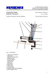
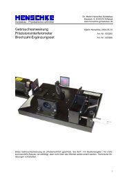
Fig. 1: Components<br />
1 Knurled screws to fasten the cross bar 8 Threaded holes to fasten magnet<br />
2 Threaded holes (5x) to mount the cross bar 9 Conductor swing suspenders<br />
3 Cross bar 10 Pendulum axle mount<br />
4 Conductor swing 11 Slotted pendulum<br />
5 Stand 12 Smooth pendulum<br />
6 M8x20 knurled screw for attaching magnet 13 Glass rod with cord and hook<br />
7 Magnet #650269 (not included) 14 Aluminium rod with cord and hook<br />
Using the electromagnetic <strong>experiment</strong> <strong>apparatus</strong> you can conduct <strong>experiment</strong>s on the force<br />
on a currentcarrying conductor, on induced eddy currents and on dia- or paramagnetism.<br />
1
1. Safety instructions<br />
When using the magnet #650269, strict compliance with the safety instructions specified for<br />
this device is imperative, e.g. warning against use by persons with cardiac pacemakers!<br />
Electric shock hazard! The maximum output voltage of the mains power supply unit being<br />
used may not exceed 40 V.<br />
Risk of injury! The glass rod (13) is fragile and must consequently be handled with care.<br />
Sharp edges of broken glass give rise to a considerable risk of injury.<br />
2. Description, technical data<br />
The <strong>apparatus</strong> consists of a rigid aluminium stand with preset magnet positions and<br />
accessory mounts. This cuts out time-consuming adjustment work. Furthermore all<br />
accessory components can be fastened onto the stand for ease of storage. The pendulums<br />
(11, 12) should be suspended in the middle of the four slots of the pendulum mount and<br />
glass and aluminium rods (13 and 14) in the outward slots so that the cords do not become<br />
tangled.<br />
The conductor swing hangs from a cross bar equipped with sockets for attaching safety<br />
plugs (4 mm). The maximum current flowing in the conductor swing should not exceed 6 A.<br />
Height of stand:<br />
Pendulum:<br />
Width of conductor swing:<br />
Rods:<br />
345 mm<br />
290 mm x 70 mm, Slot width 1 mm<br />
100 mm<br />
40 mm x 8 mm Ø<br />
3. Operation and maintenance<br />
First the stand is screwed together as specified in Fig. 1. Make sure here that the <strong>apparatus</strong><br />
is standing upright (triangular ptotractor).<br />
The braided copper strands of the conductor swing should hang smoothly down and the<br />
copper wire should be held parallel to the cross bar. If necessary the copper strands can be<br />
carefully pulled between two fingers until they are smoothed out. In the region of the<br />
soldering points the copper strands should not be bent (danger of breakage).<br />
The glass and aluminum rod are each suspended on a thin thread, which might get<br />
somewhat twisted. Before starting an <strong>experiment</strong> the rods should hung individually on the<br />
stand until they are no longer twisted.<br />
Maintenance: the electromagnetic <strong>experiment</strong> <strong>apparatus</strong> is basically maintenance-free. To<br />
clean simply wipe over it with soap and water. Solvents like aceton, petroleum ether or<br />
ethanol (white spirit or alcohol) can be used except in the area of the label.<br />
If the cord of the glass or aluminium rod have become knotted or shredded, thin sewing silk<br />
can be used as a substitute. The sewing silk thread is first wrapped around the respective<br />
rod approx. 3 times and then tied in a knot. Then the rod is suspended and balanced out<br />
horizontally by moving the sewing silk thread along the rod. Finally the sewing silk thread is<br />
permanently attached to the rod using fast-acting adhesive (observe the safety instructions of<br />
the glue manufacturer).<br />
2
4. Experiment procedure and evaluation<br />
4.1 Current-carrying conductor in a magnetic field<br />
4.1.1 Experiment setup<br />
The two possible <strong>experiment</strong> set-ups can be seen in Fig. 2.<br />
1<br />
2<br />
3<br />
2<br />
1<br />
3<br />
5<br />
F L<br />
4<br />
F G<br />
F K<br />
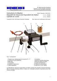
Fig. 2: Experiment setup “current carrying conductor in a magnetic field”. 1 Knurled screw,<br />
2 Cross bar, 3 Conductor swing, 4 Pole piece, 5 Flat headed knurled screw<br />
The <strong>experiment</strong> setup as specified in Fig. 2 (right) is used to verify that the Lorentz force acts<br />
neither in the direction of the magnetic field nor in the direction of current flow. In the first<br />
case the conductor swing would swing to the right or to the left, in the second case it would<br />
be forced to swing into or out of the plane of the drawing.<br />
Using the <strong>experiment</strong> setup specified in Fig. 2 (left) the Lorentz force can be demonstrated<br />
qualitatively and quantitatively. For the qualitative verification the conductor swing is<br />
suspended vertically above the poles of the magnet. When the current is switched on, we<br />
then observe deflection which gains in magnitude the more the current increases.<br />
For the quantitative determination of the Lorentz force the 3 threaded bore holes are used<br />
which are shifted at distances of 15, 30 and 45 to the left of the perpendicular holes. If, for<br />
example – as shown in the figure, the conductor swing is mounted shifted to the left by<br />
45 mm and the current flowing through the conductor swing is set so that the copper wire is<br />
right in the middle of the magnetic field, then the swing’s deflection from the vertical also<br />
amounts to precisely 45 mm and the Lorentz force corresponds to the returning force, which<br />
the conductor swing experiences due to the earth’s gravity (see also <strong>experiment</strong> evaluation).<br />
3
¡<br />
¨<br />
§<br />
4.1.2 Experiment procedure<br />
During the measurements it is expedient to note down the following variables:<br />
the <strong>experiment</strong> number,<br />
the pole piece separation a,<br />
the pole piece width in the conductor direction b,<br />
the deflection c and<br />
the current I, which flows when the copper wire is positioned in the middle 1 .<br />
Example of an <strong>experiment</strong> sequence:<br />
Exp. no. Pole piece separation<br />
a / mm<br />
Pole shoe width<br />
b / mm<br />
Deflection<br />
c / mm<br />
Current<br />
I / A<br />
1 10 50 15 0,57<br />
2 10 50 30 1,20<br />
3 10 50 45 1,87<br />
4 10 20 15 1,16<br />
5 10 20 30 2,36<br />
6 10 20 45 3,57<br />
4.1.3 Experiment evaluation<br />
The conductor swing is considered as a simple mathematical pendulum, i.e. the weight of the<br />
braided copper strands is neglected and the copper wire is seen as a point mass (m = 6.23<br />
g). The effective pendulum length s is somewhat smaller than the length of the copper<br />
strands, due to the fact that these do not fold cleanly at the upper edges, when the conductor<br />
swing is deflected. The length s is thus the result from the theoretical point where the<br />
elongation of the linear copper strands intersects with the verticals (cf. Fig. 2). In approximate<br />
terms: s = 200 mm.<br />
The resulting force on the copper strad F K is comprised of the Lorentz force F L and the<br />
weight F G and is inclined at an angle ϕ because the copper strand is (virtually) subject to no<br />
lateral forces. Consequently it is true that:<br />
<br />
<br />
=<br />
¢¤£¦¥<br />
ϕ<br />
⇔<br />
(1)<br />
=<br />
©<br />
§<br />
¨<br />
<br />
− <br />
<br />
<br />
<br />
<br />
In the above <strong>experiment</strong> sequence the pole pieces in <strong>experiment</strong>s 4 - 6 were rotated by 90°<br />
in comparison to <strong>experiment</strong>s 1 - 3. As such the conductor length which protrudes into the<br />
magnetic field changes. During the evaluation however, the true pole piece size may not be<br />
used as the basis because the magnetic field “bulges out” beyond the edges (see Fig. 3).<br />
The resulting effective length within the magnetic field is approximately:<br />
= +<br />
(2)<br />
<br />
1 If necessary, measure the horizontal distance between the copper wire and the knurled screw (5) with a nonmagnetic<br />
ruler<br />
4
¥<br />
¥<br />
Fig. 3: Bulging effects at the edges of the pole pieces<br />
The evaluation of the <strong>experiment</strong> series using Equations 1 and 2 yields the following:<br />
Exp.<br />
no.<br />
<br />
<br />
Effective<br />
conductor length<br />
b w / mm<br />
Lorentz force<br />
F L / mN<br />
Current<br />
I / A<br />
1 60 4,60 0,57<br />
2 60 9,27 1,20<br />
3 60 14,1 1,87<br />
4 30 4,60 1,16<br />
5 30 9,27 2,36<br />
6 30 14,1 3,57<br />
The result is also depicted in Fig. 4. It is immediately discernible that the Lorentz force is<br />
proportional to the current. An evaluation of the linear gradients shows furthermore that the<br />
Lorentz force is also proportional to the effective conductor length. Consequently it holds true<br />
¡ ¤ that: ∝<br />
¢ £<br />
15<br />
F / mN<br />
10<br />
5<br />
0<br />
0 1 2 3 4<br />
I / A<br />
Fig. 4: Lorentz force as a function of the current flowing in the conductor.<br />
Square symbols:<br />
¦<br />
= 60 mm, rhombuses:<br />
¦<br />
= 30 mm<br />
5
4.2 Induced eddy currents<br />
The <strong>experiment</strong> set up is depicted in Fig. 5. The pole gap amounts to approximately 10 -<br />
30 mm and is varied. If both pendulums are jointly displaced by the same angle and then<br />
released, the solid pendulum’s swing is rapidly damped (braking) to a stop, whereas the<br />
slotted pendulum undergoes several swings first.<br />
Fig. 5: Experiment set up for “induced eddy currents”<br />
Explanation: in the <strong>experiment</strong>s in section 4.1 a current was flowing through the conductor<br />
swing. This brought about a movement of charges (electrons) in a magnetic field, which<br />
evidently led to a measurable force (the Lorentz force) acting on the electrons.<br />
In this <strong>experiment</strong> too, charges – free electrons in aluminum – are set in motion in a<br />
magnetic field, whereby the motion here is of a mechanical nature. Through this motion the<br />
Lorentz force also acts on the electrons, leading to a flow of electrons, i.e. a current flowing<br />
in the aluminium, which in this <strong>experiment</strong> flows vertically from top down or vice versa<br />
depending on the motion of the pendulum.<br />
In the solid pendulum there is a kind of “shortcircuit” due to the fact that the induced current<br />
can flow back through the parts of the pendulum outside the magnetic field. This is how an<br />
eddy current arises, which can be very high and can lead to the build up of heat in the<br />
aluminium. The pendulum energy is initially converted into electrical energy and then into<br />
heat.<br />
In the slotted pendulum eddy currents cannot build up because the slots isolate the<br />
aluminium area outside the magnetic field from the area inside the field. Indeed the electrons<br />
here are also initially pushed in one direction or the other but once a great many electrons<br />
have collected at the top or bottom of the pendulum they repulse each other with the result<br />
that the voltage generated is in equillibrium with the Lorentz force and current does not flow.<br />
Thus the pendulum energy is not converted into heat.<br />
6
4.3 Dia- and paramagnetism<br />
The <strong>experiment</strong> setup corresponds in principle with Fig. 5. But now instead of suspending the<br />
pendulum we suspend either the aluminum or the glass rod in the magnetic field (prior to this<br />
please smooth out any twisted threads, see Section 3). The glass rod first starts to turn one<br />
way and then the other while the aluminum rod only very slowly (due to induced eddy<br />
currents, see last section) into its final position. After some time has elapsed the rods settle<br />
in the positions shown in Fig. 6.<br />
Fig. 6: Glass rod (left) and aluminium rod (right) in the magnetic field<br />
By loosening the knurled screw which holds the magnets and slowly turning the magnet it<br />
can be demonstrated tha the orientation of the rods remain aligned relative to the magnets<br />
and that consequently the position cannot be attributed to the rest position emerging<br />
mechanically (caused by twisted threads).<br />
Explanation: although neither glass nor aluminium are magnetic, both rods align themselves<br />
in the magnetic field. The decisive variable here is the relative permeability µ . This specifies<br />
the factor by which the flux density of the magnetic field is multiplied within the material<br />
concerned, as compared to the flux in a vacuum. Surprisingly – and in contrast to dielectric<br />
constants – the relative permeability can be greater or smaller than 1. In aluminum 2 µ =<br />
1,000023 and in glass µ = 0,99999. Thus in aluminum the flux density is amplified and the<br />
rod turns in the field direction. This effect is referred to as paramagnetism. In glass we have<br />
the opposite effect. The rod rotates out of the field and the effect is called diamagnetism.<br />
2 Grimsehl, Physik II, Ernst Klett Verlag Stuttgart, 1955<br />
7