Lorentz-motor-en.pdf - Martin Henschke Gerätebau
Lorentz-motor-en.pdf - Martin Henschke Gerätebau
Lorentz-motor-en.pdf - Martin Henschke Gerätebau
- No tags were found...

You also want an ePaper? Increase the reach of your titles
YUMPU automatically turns print PDFs into web optimized ePapers that Google loves.
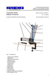
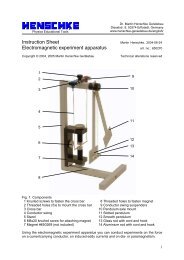
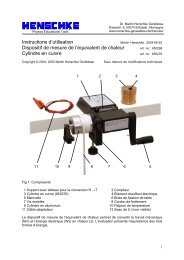
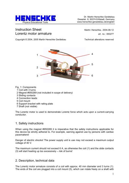
Physics Educational ToolsDr. <strong>Martin</strong> H<strong>en</strong>schke GerätebauDieselstr. 8, 50374 Erftstadt, Germanywww.h<strong>en</strong>schke-geraetebau.de/<strong>en</strong>glish/Instruction Sheet <strong>Martin</strong> H<strong>en</strong>schke, 2004-08-12<strong>Lor<strong>en</strong>tz</strong> <strong>motor</strong> armature art. no.: 650277Copyright © 2004, 2005 <strong>Martin</strong> H<strong>en</strong>schke GerätebauTechnical alterations reserved142536Fig. 1: Compon<strong>en</strong>ts1 Coil with 3 turns2 Magnet #650269 (not included in scope of delivery)3 Sliding contacts4 Connection leads5 Coil mount6 Support bracket with rating plate7 Shaft (not visible)The <strong>Lor<strong>en</strong>tz</strong> <strong>motor</strong> is used to demonstrate <strong>Lor<strong>en</strong>tz</strong> force which acts upon a curr<strong>en</strong>t-carryingconductor.1. Safety instructionsWh<strong>en</strong> using the magnet #650269 it is imperative that the safety instructions applicable forthis device be strictly adhered to. For example, warning against use by persons with cardiacpacemakers!Danger of electric shocks! The power supply unit is use may not exceed a maximum outputvoltage of 40 V.The maximum curr<strong>en</strong>t should not exceed 6 A, as otherwise the coil (1) and the slide contacts(3) will start heating up too excessively – risk of burns!2. Description, technical dataThe <strong>Lor<strong>en</strong>tz</strong> <strong>motor</strong> armature consists of a coil with approx. 40 mm diameter and 3 turns (1).The <strong>en</strong>ds of the coil are plugged into a coil mount (5), which can rotate freely on a shaft with1
an 8 mm diameter. A curr<strong>en</strong>t can th<strong>en</strong> flow continuously through the coil via the two slidecontacts (3) wh<strong>en</strong> the perceived axis through the coil is located almost perp<strong>en</strong>dicularly to themagnetic field.The perman<strong>en</strong>tly attached connection leads (4) are equipped with commercially available labsafety plugs with 4 mm diameter. In one of the leads there is also a series resistor withapprox. 0.16 ohms (not visible in Fig. 1) designed to limit the maximum <strong>motor</strong> curr<strong>en</strong>t to suchan ext<strong>en</strong>t as to avoid any disturbance to electronic control performed by standard powersupplies.3. Operating principleFig. 2: Operating principle of the <strong>Lor<strong>en</strong>tz</strong> <strong>motor</strong>. The three variables - curr<strong>en</strong>t , magnetic fieldstr<strong>en</strong>gth B and force F are all perp<strong>en</strong>dicular to each other. The direction of the force is giv<strong>en</strong>by the left-hand rule.4. Operation and maint<strong>en</strong>anceThe <strong>motor</strong> armature is inserted into hole of the magnet #650269 together with the shaftprotruding downwards from the support bracket (6). Th<strong>en</strong> the poles of the magnets arearranged so that betwe<strong>en</strong> the two poles and the coil there is a an air gap of approx. 3 mm onboth sides.The laboratory power supply unit used should be equipped with curr<strong>en</strong>t and voltage limitationand must be short-circuit proof. Before connecting the <strong>motor</strong> armature the voltage limitationmust be set to approx. 6 V and the curr<strong>en</strong>t limitation set to around 6 A.After connecting the <strong>motor</strong> armature to the mains power supply the coil may need to beturned by hand slightly until it rotates on its own. The rotation direction is predetermined hereby the curr<strong>en</strong>t direction and cannot be freely selected as is the case with “standard” <strong>motor</strong>sequipped with twopart armatures (compare the operating principle in Fig. 2).Maint<strong>en</strong>ance: Sparking may arise at the points of contact betwe<strong>en</strong> the slide contacts andthe coil, thus leading to att<strong>en</strong>d<strong>en</strong>t corrosion. This causes the <strong>motor</strong> resistance to rise and thearmature may no longer be able to turn smoothly. If this is the case, the slide contacts andthe coil <strong>en</strong>ds can be scraped clean using fine sandpaper (600 grain) or a key file. To do this itis practical to remove the coil with the coil mount from the shaft by slightly b<strong>en</strong>ding the slidecontacts outwards (facilitated by pushing a piece of cardboard betwe<strong>en</strong> the slide contact andthe coil mount).If necessary, for example, if the armature t<strong>en</strong>ds to vibrate during operation, apply a drop ofnon-acidic resin-free oil (e.g. sewing machine oil) to the bearing betwe<strong>en</strong> the coil mount (5)and shaft.2