Fresnel-Mirror.pdf - Martin Henschke Gerätebau
Fresnel-Mirror.pdf - Martin Henschke Gerätebau
Fresnel-Mirror.pdf - Martin Henschke Gerätebau
- No tags were found...

You also want an ePaper? Increase the reach of your titles
YUMPU automatically turns print PDFs into web optimized ePapers that Google loves.
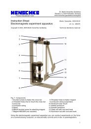
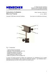
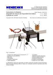
Physics Educational ToolsDr. <strong>Martin</strong> <strong>Henschke</strong> GerätebauDieselstr. 8, 50374 Erftstadt, Germanywww.henschke-geraetebau.de/english/Instruction Sheet <strong>Martin</strong> <strong>Henschke</strong>, 2006-05-16<strong>Fresnel</strong> mirror art. no.: 650272Copyright © 2006 <strong>Martin</strong> <strong>Henschke</strong> GerätebauTechnical alterations reserved1452 63Fig. 1: Components1 Protective window pane made of acrylic glass2 Stand rod, 10 mm diameter made of stainless steel3 Optical rider (not contained in the scope of supply)4 Housing made of black anodized aluminum5 Knurled screw for mirror adjustment6 Surface-coated mirror made of black acrylic glassUsing the <strong>Fresnel</strong> mirror you can perform experiments on interference of monochromatic,coherent light, whereby thanks to having two mirrors it is possible to produce two virtual lightsources – which then interfere with each other – from a single light source.1
1. Safety instructionsWhen using a laser it is imperative that all associated safety instructions specified for thedevice be strictly complied with, e.g. do NOT stare into the laser beam!During the experiment none of the observers may experience glare.2. Description<strong>Fresnel</strong>’s idea of bringing about interference in light waves reflecting off two mirrors isdepicted in Fig. 2. The light propagating from one point light source P (parallel laser beamwith lens connected upstream) is reflected by two mirrors in such a manner that the twopartial beams are superimposed on each other, thus causing interference. The experimentevaluation can easily be undertaken using mathematical methodology or graphically inphysical terms simply by determining the separation of the two virtual point light sources P 1and P 2 and then calculating the interference pattern as a superimposing of circular wavesarising from P 1 and P 2 .Fig. 2: Operating principle of the <strong>Fresnel</strong> mirror.The <strong>Fresnel</strong> mirror consists of two acrylic half mirrors each 29 mm x 45 mm in size. Since theexperiments call for a grazing incidence of light to be set, the result is total reflection and theacrylic glass functions like a surface-coated mirror. One of the two mirrors is permanentlyattached inside the housing while the other mirror is adjustable and can be tilted by an angleof approx. –0.5° up to +2°. There is a protective window pane made of acrylic glasspositioned in front of the mirrors, which may not be removed during the experiments. This isdesigned to protect against accidental contact to the mirrors. The stand rod has a diameter of10 mm and is scaled lengthwise so that the mirror’s center point has a standard height of150 mm.3. Operation and maintenanceThe <strong>Fresnel</strong> mirror is operated using grazing light incidence, whereby it is tilted by approx.1°- 2° with respect to the light beam. After adjusting the light source so that both mirrors areilluminated with equal luminous intensity, the inclination of the two reflected light beams canbe adjusted with respect to each other by turning the knurled screw (5).2
Maintenance: the <strong>Fresnel</strong> mirror is basically maintenance-free. To clean simply wipe cleanusing a damp rag with detergent. If possible the mirror should only be dry dusted using a softbrush. If necessary it can also be cleaned with a detergent and a soft rag.Storage: this device should be stored in a dust-free location, perhaps completely coveredwith a plastic bag.4. Experiment procedure and evaluationThere are two experiment setups described below. In Section 4.1 a simple and compactassembly is presented which leads to thick and bright interference bands, but which havepreviously not been quantitatively evaluated. Section 4.2 shows the assembly for the“classical” experiment and has a basic evaluation example.4.1 Compact, qualitative interference experimentFollowing equipment is required:1 x Optical bench with triangular profile, 0.5 m long1 x Optical rider, 120 mm high, 50 mm wide1 x Optical rider, 90 mm high, 50 mm wide2 x Optical rider, 60 mm high, 50 mm wide1 x Extension arm1 x He-Ne-laser1 x <strong>Fresnel</strong> mirror1 x Diverging lens, f = 5 mm1 x Observation screenFig. 3: Experiment setup “Compact Interference Experiment”The experiment setup can be seen in Fig. 3. The <strong>Fresnel</strong> mirror is tilted by approx. 1° withrespect to the laser. Initially the lens is still pivoted out of the beam. By turning the laser inthe optical rider the beam is adjusted so that it incidents on both mirrors and produces twoequally bright points on the observation screen (if necessary, slightly adjust the mirror tilt byturning the knurled screw [5]). Then by turning the knurled screws you can adjust the twopoints on the screen until they are coincident. If you now pivot the lens into the beam axis, an3
interference pattern should already appear on the screen, which then can be made evensharper still by readjusting the laser.4.2 Classical interference experiment4.2.1 Experiment setupFollowing equipment is required:1 x Optical bench with triangular profile, 0.5 m long1 x Optical rider, 120 mm high, 50 mm wide1 x Optical rider, 90 mm high, 50 mm wide2 x Optical rider, 60 mm high, 50 mm wide1 x He-Ne laser1 x <strong>Fresnel</strong> mirror1 x Diverging lens, f = 5 mm1 x Diverging lens, f = 200 mmThe experiment setup can be seen in Fig. 4. At first the laser and the diverging lens aremounted and aligned so that the laser beam diverged by the lens propagates almost parallelto the optical bench. The beam trajectory can be made visible using a sheet of paper. Do notlook directly into the beam! Subsequently the <strong>Fresnel</strong> mirror is mounted at an inclination ofaround 1 - 2° with respect to the laser.Fig. 4: Experiment setup “Classical Interference Experiment”. Position of components (leftedge of the optical rider): laser: 0 mm, lens f = 5 mm: 150 mm, <strong>Fresnel</strong> mirror: 220 mm, lensf = 200 mm (only mounted when the distance to the virtual light source is measured): approx.380 mm. The interference image is obtained on the screen (or a brightly lit wall) at a distanceof 2 to 3 m.By turning the knurled screw (5) an image should now appear in focus on the screen 2 - 3 mmeters away which basically corresponds to Fig. 5. There will still be visible a bright areanext to the interference pattern, which stems from the light which misses the mirrors. Besidesthe bands of the actual interference pattern it is possible to see still more interference bandsand rings depending on the quality and degree of cleanliness of the laser and lens. Adefinitive conclusion regarding which bands are actually caused by the mirrors is easy toobtain simply by adjusting the knurled screw (5). Only the bands which vary their widthduring this adjustment are “real” interference bands. Their distance should be adjustablefrom approx. 1 – 4 mm.4
Fig. 5: Interference image on the observation screen. A bright band can still be discerned atthe left edge, which stems from the light that does not hit the mirror.4.2.2 Experiment procedureDuring one experiment the separation D of the interference bands is determined first. If theseparation amounts to, for example, 24 ± 1 mm between 7 maxima, then D = 3.43 mm.Afterwards the 200 mm lens is mounted and, if needed, somewhat shifted until two clearlydiscernible light spots appear on the screen with a distance of about 3 - 15 mm from eachother (the light missing the mirror produces a third spot at a greater distance farther to theleft). Here it may be beneficial for the measurement if the light spots are somewhat largerthan the minimum size obtained when the lens is sharply focussed. In this example thedistance of the light spots amounts to A = 6.8 mm and was determined using a measurementcaliper.The last variable needed for the evaluation is the distance b between the 200 mm lens andthe observation screen (b = 2700 mm).4.2.3 Experiment evaluationAs was already explained on the basis of Fig. 2, the interference image can be interpreted asthe superimposing of the light from two point light sources P 1 and P 2 . In order for an intensitymaximum to be produced on the observation screen the ray’s path difference d between twobeams originating from P 1 and P 2 must correspond precisely to the wavelength or amultiple integer of . Using the variables defined in Fig. 6 we obtain the followingdaandDL= sinϕ= tanϕ . (2)At a sufficiently low angle ϕ it holds true that sinϕ≈ tanϕ. Furthermore let us assume thatd = (first maximum). As a result it follows from Equations 1 and 2 that:Dλ = a(3)L(1)5
Fig. 6: Intensity maxima arise when d = n(n being an integer).Fig. 7: Determination of the separation a between the virtual point light sources using a lens(e.g. f = 200 mm). The distances A and b are measured.The determination of the separation a of the virtual point light sources is depicted in Fig. 7.By using the intercept theorems we directly obtain the two correlationsa g = (4)A bandaAg − f= . (5)fEqualizing the two equations for the elimination of a/A and resolving for g results inbfg = . (6)b − fIf this is inserted in Equation 4, a can be determined and inserted in Eq. 3. The still missingvalue for the length L in Eq. 3 results according to Fig. 7 from the sum of the two distances gand b. When everything is inserted into Eq. 3 it yields:λ =ADfb 2For the example the result is = 640 nm, which is in good agreement with the manufacturer’sspecifications for the laser being used (632.8 nm).6