Ballistic-Pendulum.pdf - Martin Henschke Gerätebau
Ballistic-Pendulum.pdf - Martin Henschke Gerätebau
Ballistic-Pendulum.pdf - Martin Henschke Gerätebau

You also want an ePaper? Increase the reach of your titles
YUMPU automatically turns print PDFs into web optimized ePapers that Google loves.
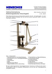
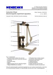
Physics Educational ToolsDr. <strong>Martin</strong> <strong>Henschke</strong> GerätebauDieselstr. 8, 50374 Erftstadt, Germanywww.henschke-geraetebau.de/english/Instruction Sheet <strong>Martin</strong> <strong>Henschke</strong>, 2004-06-21<strong>Ballistic</strong> <strong>Pendulum</strong> art. no.: 650273Copyright © 2006 <strong>Martin</strong> <strong>Henschke</strong> GerätebauTechnical alterations reserved1 2 3 4 567891011141312Fig. 1: Components1 Ball launcher (650267)2 Back plate3 Guide for swing pointer4 Bearing screw5 Counter bearing6 Swing pointer7 Angle scale8 <strong>Pendulum</strong>9 Ball catcher10 Base plate11 Table clamp12 Knurled screw13 Ramrod (delivered with 650267)14 Extra weights, 2 pcs.1
1. Safety instructionsThis instruction sheet is concerned mainly with the ballistic pendulum. You should also readthe instructions for the ball launcher 650267.To check whether a ball is located in the ball launcher and the spring is cocked, only use theobservation holes at the sides. Do not look into the barrel from the front. Risk of injury!Never aim at people!Protective goggles should be worn during the experiments.The ball launcher should always be stored with the spring loose and with no ball in the barrel.2. DescriptionThe ballistic pendulum is for experiment-based determination of the launch velocity of a ballwhen it leaves the ball launcher. It is also possible to determine trajectories when the ball islaunched horizontally or at an angle. Launch heights of 5, 10, 15, 20 or 30 cm can beselected easily with the aid of the drilled holes.Thanks to the extreme lightness of the pendulum, the experiment can be performed usingcomparatively safe plastic balls instead of steel balls. Experiments involving inelasticcollisions (quantitatively) and elastic collisions (qualitatively) can be evaluated. The velocityof the balls determined from trajectory and pendulum experiments typically agree to withinabout 3%.Extra weights allow various pendulum travels to be investigated for constant speeds.3. Operation and maintenanceFirst the ballistic pendulum is screwed to a stable bench by means of its clamp. The balllauncher is then screwed to the back plate (2) from behind either in a horizontal position infront of the pendulum as in Fig. 1 or as shown in Fig 3.Tip: if the workbench is not stable enough, it may be that when the pendulum swings to itsmaximum extent and then swings back, it may jog the apparatus when striking the balllauncher, causing the swing pointer to be shifted out of line. If this happens, the pendulumshould rather be stopped by hand.Balls should always be loaded when the spring is not under tension by placing the sphere inloosely through the front of the plastic cylinder within the device. The sphere is then pusheddown inside the barrel using the ramrod until the desired spring tension has been reached.The ramrod should not be removed too quickly, otherwise the suction its removal producesmay pull the sphere out with it. The position of the sphere may only be checked using theobservation holes. Never look into the barrel!Before launching, ensure that no one is in the way of the trajectory. To launch, the cord ofthe launching lever is briefly pulled perpendicularly to the lever.The pendulum (8) can be removed by undoing the bearing screw (4) and turned by 180° sothat it is installed with the rear of the ball catcher (9) pointing towards the launcher(experiments on elastic collision). The counter bearing (5) is designed so that the pendulumhangs at a slight angle if the bearing screw is only light tightened. This means that the ball2
catcher is not precisely in front of the launch aperture of the launcher. For this reason, thebearing screw should be tightened until the catcher and the launch aperture are in line.After turning the pendulum round, or if necessary, the guide (3) for the swing pointer (6)should be adjusted so that the pointer just touches it when the pendulum is suspended atrest. The screw on the guide should only be finger-tightened to avoid the appearance ofpressure on the pendulum rod.Maintenance:the ballistic pendulum principally requires no maintenance. If necessary some non-acidgrease (Vaseline) can be applied to the bearing screw (4) and the knurled screw (12). Otherthan in the vicinity of the scale, the apparatus may be cleaned using acetone, ethanol (whitespirit) or petroleum ether as required. Avoid submerging the equipment in water.4. Experiment procedure and evaluation4.1 <strong>Ballistic</strong> pendulum4.1.1 Experiment setupThe experiment setup corresponds to Fig. 1 for experiments on inelastic collision. Forexperiments on elastic collisions, the pendulum should be turned round by 180° (cf. Section3 „Operation“).4.1.2 Experiment procedureIt is practical for these experiments to enter the experiment number, the spring tension (1, 2or 3), the type of collision (inelastic „i“ or elastic „e“), the number of extra weights used andthe measured angle ϕ . In order to obtain the most accurate experiment results, after oneshot, a second should be performed with the swing pointer not having been reset to 0° inbetween. This minimizes the unavoidable frictional losses of the swing pointer.Example experiment sequence:No Spring Type of Extra weights Angle ϕtension collision1 1 i 0 17.52 2 i 0 25.03 3 i 0 36.04 1 i 2 9.55 2 i 2 13.56 3 i 2 19.07 1 e 0 29.58 2 e 0 42.09 3 e 0 60.03
4.1.3 Experiment evaluation4.1.3.1 Inelastic collisionThe following equation is valid for the swinging pendulum due to conservation of energyE = (1)pot E kinwhere the potential energy isE = m g ∆h(2)pottotHere is mtotthe total mass of the pendulum including the ball and any extra weights, g is theacceleration due to gravity and ∆ h is the difference in height of the center of gravity of thependulum at rest and at the maximum extent of its swing. From the measured angle ϕ andthe measured length l Sto the center of gravity according to Fig.2 the following is derived:∆ h = ( 1−cosϕ)(3)l SFig. 2: Determining the required lengths. Distance between center of gravity and axis ofrotation ( l S) should be measured including the ball and any additional weights when thecollision is inelastic. To perform the measurement, the pendulum may, for example, bebalanced on a ruler mounted on its side. The distance between the center of the ball and theaxis of rotation is l K= 280 mm.The kinetic energy can be calculated from the moment of inertia Ιtotrelative to the axis ofrotation and the maximum angular speed ω according to the equation1 2Ekin= Ιtotω . (4)2If Equations 2 and 4 are inserted into Equation 1 and ∆ h eliminated using Equation 3 thenthe equation can be rearranged to:2mtot g l S (1 − cosϕ)ω =(5)ΙtotHowever, we are not seeking ω , but the initial velocity of the ball v0. The relationshipbetween the two values is given by the equation for the conservation of angular momentumdirectly before and after the collision:LK= L tot(6)with the angular momentum of the ballLK = mKlKv (7)0before the collision and the total angular momentumLtot= Ιtotω(8)after the collision. Inserting Eqs. 7 and 8 into Eq. 6 gives:mKlKv0 = Ιtotω(9)4
Resolving this for ω and equating with Eq. 5 leads to the following relationshipv 10 = 2Ιtotmtotg lS(1− cosϕ)m l(10)K KThe moment of inertia is in principle determined from the integralΙ = l 2 dm(11)tot∫mwhere l is the distance of each mass element dm from the axis of rotation. Since in this caseit is not the moment of inertia that we seek to derive Ιtotcan also be calculated from theperiod T of the pendulum (with ball and any extra weights). For a physical pendulum thefollowing is valid for small deflections 1 :2⎛ T2 ⎟ ⎞Ιtot = mtotg lS⎜(12)⎝ π ⎠This means that all the variables are now known or calculable. For the above example, thefollowing table emerges:NomK/ kgmtot/ kg l S/ m T / s v 0 in m/s1 0.00695 0.06295 0.218 1.01 3.392 0.00695 0.06295 0.218 1.01 4.823 0.00695 0.06295 0.218 1.01 6.884 0.00695 0.09795 0.252 1.07 3.515 0.00695 0.09795 0.252 1.07 4.986 0.00695 0.09795 0.252 1.07 6.99The numeric values should be determined separately for every pendulum, since material andmanufacturing tolerances mean that values may differ from one to another.4.1.3.2 Elastic collisionFor a swinging pendulum Eq. 5 is still valid for the motion after a collision, the only differencebeing that the moment of inertia Ι Pis determined without the ball but with any extra weights(pendulum mass m P ):2mg (1 − cosϕ)ΙP lω =S(13)PTo determine the relationship between ω and the initial velocity v0both the conservation ofangular momentum and the conservation of energy before and after the collision must nowbe used. The additional equation is required since the system has an additional degree offreedom in the ball velocity v2after the collision. As for Eq. 9, the following is true for theangular momentum:m l v = m l v + Ι ω⇔vK K= v0KKΙ ω−P2 0mKlKIf this velocity 21mKv2122Pinserted into the equation for the conservation of energy1Pω22220= mKv2+ Ι(15)(14)1 Recknagel, A.: Physik Mechanik, 3te Auflage, VEB Verlag Technik Berlin, 19585v is
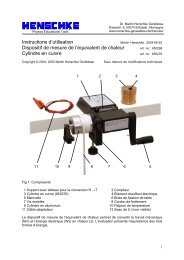
y rearranging in various steps the following expression is obtained for v01 ⎛ ΙP⎞v ⎜ ⎟0= ω lK1+22(16)⎝ mKlK⎠If Eq. 13 is plugged in here and Ι Pdetermined as in Eq. 12, then v0can be calculated for anideal inelastic collision:NomK/ kgmP/ kgl / m T / s vS0 in m/s7 0.00695 0.0560 0.211 1.008 2.888 0.00695 0.0560 0.211 1.008 4.059 0.00695 0.0560 0.211 1.008 5.65These values for v0are about 18% smaller than those obtained for inelastic collisions. Thiscan be explained by the fact that the elastic collisions are not entirely ideal.4.2 Determination of trajectories4.1.1 Experiment setupOne possible experiment setup is shown schematically in Fig. 3 (not to scale). The drill holesin the back plate of the pendulum are placed so that when a ball is fired to land directly onthe workbench, the launch heights are 50, 100, 150, 200 and 300 mm.1 2 3 4 5Fig. 3: Experiment setup, key: 1 Ball launcher, 2 Launch position of the ball, 3 Paper,4 Carbon paper, 5 Easel with whiteboard (for example)6
When launching against a vertical wall (e.g. whiteboard) the radius of the ball (1.25 cm)should be subtracted from the distance between the point of launch and the wall to obtain thedistance measurement x M . The height measurement y M relative to the launch height is givenby the height of the impact on the wall minus 62.5 mm, 112.5 mm, 162.5 mm, 212.5 mm or312.5 depending on the hole used.4.1.2 Experiment procedureIt is practical for these experiments to note the experiment number, the spring tension (1, 2or 3), the launch angle and the values x M and y M . Example:No Springtensionlaunch angle ϕ /° distance x M / cm target height y M /cm1 1 0 171.3 -302 2 0 125.4 -303 3 0 86.9 -304 1 0 62.3 -155 2 0 90.5 -156 3 0 120.7 -154.1.3 Experiment evaluationIt is practical to take as the origin of the coordinate system the mid-point of the ball at themoment of launch. Then the following applies:v x= cosϕ(17)v 0v y = v 0 sinϕ(18)1 y = v t g t2y−2(19)x = v t(20)xFrom Eq. 20= x vx, whereby the time can be eliminated from Eq.19. Ifxt /v andv y arethen eliminated from the resulting equation using Eqs. 17 and 18, the following is obtainedgy = x tanϕ− x2(21)2v2cos2ϕ0This is the equation for the trajectory. In this equation only the launch velocity v 0 is unknownsince the distances x and y were measured during the course of the experiments. If v 0 iscalculated for the various experiments, the following results are obtained:Spring tension v 0 in m/s1 3.532 5.103 6.85The numbers are based on a total of 25 experiments, of which only 6 are explicitly listed inthe above table. The trajectory can now be obtained from these using Eq. 21 and comparedto the measured values. The result is shown in Fig. 4.7
0-0,1y / m-0,2-0,3-0,40 0,5 1 1,5 2x / mFig. 4: Comparison of measurements and calculated curve, x = horizontal ball distance, y =vertical height, symbols = measured values (circles = spring tension 1, squares = springtension 2, rhombuses = spring tension 3), lines = calculated trajectories8