Model PS 3002 Electrophoresis Power Supply - Biometra
Model PS 3002 Electrophoresis Power Supply - Biometra
Model PS 3002 Electrophoresis Power Supply - Biometra

You also want an ePaper? Increase the reach of your titles
YUMPU automatically turns print PDFs into web optimized ePapers that Google loves.
<strong>Model</strong> <strong>PS</strong> <strong>3002</strong><br />
<strong>Electrophoresis</strong> <strong>Power</strong> <strong>Supply</strong><br />
CAT. NOS. 31067-234<br />
2<strong>3002</strong>-017
Table of Contents<br />
1. Introduction ................................................................................................. 1<br />
1.1 Notice to Customer................................................................................... 1<br />
1.2 Warnings .................................................................................................. 1<br />
2. Overview ....................................................................................................... 2<br />
2.1 Description................................................................................................ 2<br />
2.2 Set-Up ...................................................................................................... 2<br />
3. Operating Instructions............................................................................ 4<br />
3.1 Operation in Constant Voltage.................................................................... 4<br />
3.2 Operation in Constant Current .................................................................... 5<br />
3.3 Operation in Constant Watts....................................................................... 5<br />
3.4 Choosing Safe Operating Limits ................................................................. 5<br />
3.5 Automatic Crossover.................................................................................. 6<br />
4. Troubleshooting Guide ........................................................................... 7<br />
5. Related Products....................................................................................... 8<br />
6. Additional Information ............................................................................ 9<br />
5.1 Care and Handling.................................................................................... 9<br />
5.2 Specifications............................................................................................. 9<br />
5.3 Warranty.................................................................................................. 10<br />
5.4 Declaration of Conformity and CE Mark ................................................. 10<br />
Figure<br />
1. <strong>Model</strong> <strong>PS</strong> <strong>3002</strong> <strong>Electrophoresis</strong> <strong>Power</strong> <strong>Supply</strong> ................................................. 3<br />
GEL-MIX ® , HORIZON ® , RUNNING MATE, THE ILLUMINATOR, THE COURIER, TECH-LINE SM , and the Life<br />
Technologies logo are marks of Life Technologies, Inc.<br />
i
Introduction<br />
1<br />
1.1 Notice to Customer<br />
!<br />
This product is authorized for laboratory research use only. The product has not<br />
been qualified or found safe and effective for any human or animal diagnostic or<br />
therapeutic application. Uses for other than the labeled intended use may be a<br />
violation of applicable law.<br />
1.2 Warnings<br />
1. DANGER! HIGH VOLTAGE! This power supply has been designed for use as a<br />
source of DC power for electrophoresis. It is capable of generating lethal<br />
currents. This unit should always be operated with extreme caution. Careless<br />
handling could result in electrical shock.<br />
2. Never operate damaged equipment. Do not use the unit without the cover in<br />
place or with any possible short circuit. If the power supply emits smoke or<br />
continually blows the main fuses, turn off the power supply and disconnect the<br />
AC line and power cord.<br />
3. Do not operate with connecting cables that have exposed live wires.<br />
4. Always turn off the power supply before connecting or removing the power cords<br />
or moving an electrophoresis apparatus.<br />
5. Handle one power cord at a time, with one hand only, when connecting or<br />
removing DC power cords at the power output terminals.<br />
6. Do not immerse this unit in water.<br />
7. Do not operate the unit in a damp, humid atmosphere or in a fashion where<br />
condensed moisture may short out electrical components.<br />
8. Do not connect the output to earth ground.<br />
9. The AC power cord has a three-pronged plug which must be connected to a<br />
grounded line voltage receptacle. Do not use a two-wire receptacle with an<br />
adapter. This could create a serious electrical hazard for persons using the unit.<br />
10. Use the correct voltage AC power outlet for the power supply. Be sure to always<br />
plug a 110 VAC power supply into a 110-V line, and use a 240-V line with a 240<br />
VAC unit.<br />
1
2<br />
Overview<br />
2.1 Description<br />
The <strong>Model</strong> <strong>PS</strong><strong>3002</strong> <strong>Electrophoresis</strong> <strong>Power</strong> <strong>Supply</strong> is intended to be used with<br />
electrophoretic devices that operate below 3000 V DC and up to 300 W, and/or 300<br />
mA. The unit includes two sets of output sockets which operate in parallel to provide<br />
output in constant voltage, constant milliamps, or constant power (see figure 1).<br />
This power supply has the ability to restart itself in the event of an AC mains power<br />
failure.<br />
2.2 Set-Up<br />
Unpacking the Unit. Unpack and inspect the power supply unit carefully for any<br />
damage. Do not use the unit if it is damaged. If damage is found, save the packing<br />
material and report the problem to Life Technologies Customer Service.<br />
Location. Make sure that the unit is set up in a location where it is protected from<br />
physical damage, moisture, corrosive agents, and extreme temperatures. Make sure<br />
that the fan at the rear is not obstructed; leave about 5-cm space behind the unit.<br />
The unit should be readily accessible for safe operation.<br />
Connection with the AC Mains. Connect the unit to the AC mains carrying the<br />
appropriate specified voltage (V) in accordance with the rating label affixed to the<br />
back of the unit. Ensure that the main receptacle and the power supply plug both<br />
have the proper three-wire (grounded or earthed) connections.<br />
2
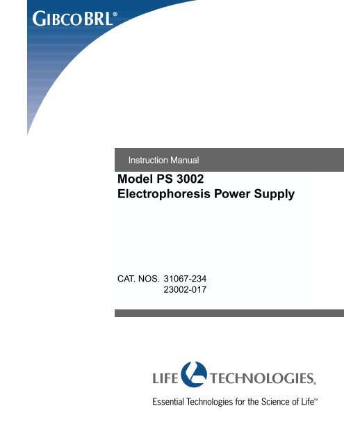
Overview<br />
2<br />
Volts, Red<br />
At Limit Light<br />
Volts Display<br />
Milliamps, Red<br />
At Limit Light<br />
Milliamps Display<br />
Watts, Red<br />
At Limit Light<br />
Watts Display<br />
DC Output Off,<br />
Red Light<br />
GIBCOBRL<br />
4-mm Sockets<br />
+<br />
DANGER<br />
HIGH VOLTAGE<br />
-<br />
LIFE TECHNOLOGIES<br />
V3000 Volts<br />
mA<br />
300 mA W300 Watts<br />
ELECTROPHORESIS POWER SUPPLY <strong>PS</strong> <strong>3002</strong><br />
FAULT<br />
STOP<br />
START<br />
PRESET<br />
DC Output<br />
Stop Key<br />
DC Output<br />
Start Key<br />
DC Output On,<br />
Green Light<br />
Preset View Key<br />
Volts Adjustment<br />
Knob<br />
Milliamps Adjustment<br />
Knob<br />
Watts Adjustment<br />
Knob<br />
Fault Light,<br />
Yellow<br />
<strong>Power</strong> On/Off<br />
Switch<br />
Figure 1. <strong>Model</strong> <strong>PS</strong><strong>3002</strong> <strong>Electrophoresis</strong> <strong>Power</strong> <strong>Supply</strong><br />
3
3<br />
Operating Instructions<br />
In order to achieve the greatest efficiency and effectiveness from this unit, read this<br />
section in its entirety before setting up or operating the power supply unit and<br />
carefully review figure 1 to ascertain the location of the power supply’s controls and<br />
features.<br />
3.1 Operation in Constant Voltage<br />
1. Place the power supply on a sturdy, level surface in a safe, dry place away from<br />
laboratory traffic. Controls must be easily accessible and sufficient space must<br />
be available nearby for the electrophoresis unit(s) to be used with the power<br />
supply. The fan intake in the back and exhaust on the bottom must remain<br />
unobstructed.<br />
Note: Allow at least 8 h for the unit to equilibrate if it is moved into or out of a<br />
cold room. It must be completely dry before using.<br />
2. The electrophoresis chamber should be set up, then filled with buffer, before<br />
plugging the chamber’s leads into the appropriate positive and negative 4-mm<br />
sockets on the power supply unit.<br />
Note: Sample can be added before or after adjusting power supply settings.<br />
3. Switch on the power supply using the <strong>Power</strong> On/Off switch. Once on, the red<br />
DC Stop light will be illuminated. The Volts display, Milliamps display, and Watts<br />
display will all indicate zero.<br />
Notes on General Operation: The output of the unit is controlled by three<br />
separate operating parameters. An operating limit, with a value above zero,<br />
must be set for voltage, milliamps, and watts to generate an output. When the<br />
power supply unit is activated, the output of the power supply will steadily<br />
increase until an operating limit is reached. Once an operating limit is reached,<br />
one of the three red At Limit lights will illuminate. The light will indicate which<br />
operating limit has been reached first and which mode of control has been<br />
established.<br />
4. Using the Volts adjustment knob, select the operating voltage limit by turning the<br />
knob until the desired value appears on the Volts display. Rotating the knob<br />
slowly in a clockwise direction will increase the displayed value in 10-V<br />
increments. Rotating the knob slowly in a counterclockwise direction will reduce<br />
the displayed value in the same manner. As soon as the adjustment knob is<br />
rotated, the output displays will show set values. When released, the set value<br />
will remain illuminated for 3 seconds and then display the actual output values.<br />
Note: The DC output must be off to change the output settings.<br />
5. Using the Milliamps Adjustment knob and Watts Adjustment knob, select the<br />
desired operating limits for milliamps and watts, respectively. The method used<br />
to select these values is the same method used to select the operating voltage<br />
limit.<br />
Warning: The <strong>Model</strong> <strong>PS</strong> <strong>3002</strong> <strong>Power</strong> <strong>Supply</strong> Unit is capable of producing output<br />
levels well in excess of the maximum safe operating limits for most<br />
electrophoretic chambers. It is important to determine the safe operating limits<br />
for milliamps and watts. Section 3.4 has been included to guide the user in<br />
selecting proper operating parameters.<br />
4
Operating<br />
Instructions<br />
6. Press the green DC Output Start key. The green DC Output On light should be<br />
illuminated and the DC output, as indicated by the three displays, should rapidly<br />
increase until the operating voltage limit is reached. At this point the red At Limit<br />
light (volts) should be illuminated.<br />
7. At the end of electrophoresis, turn off the power supply using the DC Output<br />
Stop key and disconnect the leads.<br />
3.2 Operation in Constant Current<br />
The method used to set the power supply in constant current is the same as the<br />
method used for constant voltage. The only difference involves the selection of an<br />
operating limit for current which, as the output increases, is attained before the<br />
operating limits for voltage or watts.<br />
3.3 Operation in Constant Watts<br />
The method used to set the power supply in constant watts is the same as the<br />
method used to set constant voltage with one notable difference. The difference<br />
involves the selection of an operating limit for watts which, as the output increases,<br />
is attained before the operating limits for voltage or current.<br />
3.4 Choosing Safe Operating Limits<br />
Electrophoretic chambers are generally designed for a relatively specific purpose.<br />
For example, submarine chambers use agarose gels to separate DNA or RNA<br />
fragments, while a DNA sequencing chamber is almost always used to separate<br />
DNA in a denaturing polyacrylamide gel. In each case, the voltage, milliamp, and<br />
wattage requirements are well defined within a reasonable range of values. In cases<br />
such as these, the user can safely assume that the manufacturer has designed the<br />
chamber to withstand the voltage and heat energy necessary to perform the<br />
electrophoretic separation when standard protocols are followed.<br />
Some types of electrophoretic chambers are specifically designed to be<br />
multipurpose devices. For example, a vertical slab gel chamber could be used for<br />
anything from DNA sequencing to isoelectric focusing, depending on the gel type<br />
and buffer system used. Choosing safe operating limits for a chamber of this type<br />
requires a higher degree of caution. Chamber manufacturers normally rate their<br />
product for maximum voltage and/or maximum wattage. Whenever possible,<br />
contact the manufacturer and request this information.<br />
Whether you use special purpose or multipurpose chambers, the maximum<br />
operating temperature the chambers will withstand is a critical aspect of safe<br />
operation. Most electrophoretic chambers (with a few notable exceptions) are made<br />
of acrylic and plastic and should operate below a temperature of 35°C. If there is a<br />
lack of information about the capabilities of the chamber being used, regular<br />
monitoring of the operating temperature is recommended. This should be<br />
accomplished without coming into physical contact with the chamber when voltage<br />
is applied. Use the procedure listed below to select operating parameters.<br />
1. Set voltage as described in steps 1–4 for operation in Section 3.1.<br />
2. Using the Milliamps and Watts adjustment knobs, select the maximum operating<br />
limits of 300 mA and 300 W, respectively.<br />
3. Press the green DC Output Start key. The green DC Output On light should<br />
illuminate and the DC output, as indicated by the three displays, should rapidly<br />
increase until the operating voltage limit is reached. At this point the red At Limit<br />
light (volts) should be the only ‘at limit’ light illuminated.<br />
4. Once the power supply has reached the operating voltage limit, note the actual<br />
number of milliamps and watts displayed and press the red DC Output Stop key.<br />
Confirm that the red DC Output Off light is illuminated.<br />
3<br />
5
Operating<br />
Instructions<br />
5. Add 15 mA and 10 W to the actual values noted earlier. Using the adjustment<br />
knobs, set the operating limits to the new values.<br />
6. Press the green DC Output Start key. The green DC On light should illuminate<br />
and the DC output displays should rapidly increase until the operating voltage<br />
limit is reached. The red At Limit light for volts should be the only one<br />
illuminated.<br />
Note: It may be necessary to readjust the watt or milliamp operating limit during<br />
electrophoresis to ensure that the entire procedure is performed at a constant<br />
voltage. This readjustment, if necessary, is required to compensate for large<br />
changes in resistance which occur during certain types of electrophoresis (see<br />
Section 3.5).<br />
Note: To view the output settings during electrophoresis, press the yellow<br />
preset key. The LED’s will display the set output values as long as the key is<br />
depressed. Once released, the LED’s will display the set values for 3 seconds<br />
and then switch to the actual output values.<br />
3.5 Automatic Crossover<br />
For some electrophoresis conditions, a function of this power supply unit known as<br />
automatic crossover will occur. Automatic crossover is the ability of the unit to<br />
change the mode of operation during the course of an experiment. As conditions of<br />
buffers and gels change during a run, a constant voltage run may, for example,<br />
become limited by current or power if the limit for either of these other values is<br />
reached. This automatic crossover process is used to protect both the experiment<br />
and equipment.<br />
6
Troubleshooting Guide<br />
4<br />
This power supply is equipped with both audible and visual alarms to help you<br />
troubleshoot. Many operating problems may be solved by reading and carefully<br />
following the instructions in this manual. Some suggestions for troubleshooting are<br />
given below. Should these suggestions not resolve the problem, contact the TECH-<br />
LINE SM<br />
at the number listed on the back of this manual. Should the power supply<br />
need to be returned for service, contact Customer Relations for instructions. Include<br />
a full description of the problem.<br />
Symptom Problem Comment<br />
An alarm sounds and Open connection Depress the red DC Output Stop<br />
is accompanied by the<br />
key to cancel the alarm mode.<br />
illumination of the yellow<br />
fault light.<br />
This power supply is equipped<br />
with a load sensing interlock<br />
which is designed to inhibit the<br />
generation of high voltage<br />
whenever an open connection<br />
is detected at the output.<br />
An open connection could be<br />
caused by any of the following<br />
conditions:<br />
1. A broken electrode within the<br />
electrophoretic chamber.<br />
2. A broken wire within a<br />
connecting cord.<br />
3. Insufficient buffer levels in<br />
the electrophoretic chamber.<br />
4. Loose connectors.<br />
5. Electrochemical energy<br />
stored within the chamber.<br />
Ground leakage is<br />
detected<br />
Turn off the unit.<br />
The voltage and wattage Ground leakage is Do not operate the power supply<br />
displays hold their last detected when this condition exists.<br />
value and the milliamps<br />
For further assistance, call the<br />
display is blank.<br />
TECH-LINE.<br />
Alarm sounds for <strong>Power</strong> on restart Auto-restart will occur at the end<br />
10 seconds. of a mains power failure. The<br />
alarm will clear itself.<br />
7
5<br />
Related Products<br />
Product<br />
Cat. No.<br />
<strong>Model</strong> 4001 <strong>Electrophoresis</strong> <strong>Power</strong> <strong>Supply</strong> 31067-069<br />
<strong>Model</strong> 4001P Programmable <strong>Electrophoresis</strong> <strong>Power</strong> <strong>Supply</strong> 31067-119<br />
<strong>Model</strong> S2 Sequencing Gel <strong>Electrophoresis</strong> System 21105-010<br />
<strong>Model</strong> SA-32 Sequencing Gel <strong>Electrophoresis</strong> System 31096-019<br />
<strong>Model</strong> SA-60 Sequencing Gel <strong>Electrophoresis</strong> System 31096-035<br />
<strong>Model</strong> SA-88 Sequencing Gel <strong>Electrophoresis</strong> System 31096-050<br />
GEL-MIX ® 6 6% Sequencing Gel System 15543-010<br />
GEL-MIX 8 8% Sequencing Gel System 15545-015<br />
GEL-MIX RUNNING MATE 10X TBE Buffer 15546-013<br />
dsDNA Cycle Sequencing System (100 reactions) 18196-014<br />
<strong>Model</strong> GDS2000 Gel Dryer 10384-030<br />
<strong>Model</strong> GD40/50 Gel Dryer 10384-014<br />
THE ILLUMINATOR Autoradiographic Filmviewer 10241-313<br />
Intensifying Screen 35!43 10241-131<br />
THE COURIER 35!43 Film Cassette 10241-057<br />
S2 Casting Clamp 21105-432<br />
S2 Casting Clamp (2/pk.) 21105-473<br />
Large Vertical Multicaster 21220-207<br />
Glass Plate Wash Stand 21105-655<br />
Accessories or Replacement Parts:<br />
Fuse, T 4.0 A, 250 V 31067-275<br />
Fuse, T 2.0 A, 250 V 31067-283<br />
8
Additional Information<br />
6<br />
5.1 Care and Handling<br />
This power supply uses all solid-state components and should require no<br />
maintenance or recalibration under normal use. If the unit must be returned for<br />
repair, contact Life Technologies’ Customer Service Department for shipping<br />
instructions. Please include a full description of the problem. As with any laboratory<br />
instrument, adequate care ensures consistent and reliable performance.<br />
The power supply must not be immersed in water. The unit can be wiped with a soft<br />
cloth, dampened with water and a nonabrasive, mild soap or detergent. Do not<br />
allow water to enter the case. Abrasive cleaners, window sprays or rough cloths<br />
may damage the surface and should be avoided. Grease and oils may be removed<br />
using a light application of hexane, kerosene or aliphatic naphtha. Do not expose<br />
the surface to phenol, acetone, benzene, halogenated hydrocarbon solvents or<br />
undiluted laboratory alcohols. Avoid prolonged exposure of the power supply to UV<br />
light. A soft, dry cloth may be used to dry the unit.<br />
5.2 Specifications<br />
Net Weight: ........................................................................................................... 6 kg (13.2 lb)<br />
Dimensions: ............................................................................................ 27.2 " 34.7 " 11.0 cm<br />
(D " W " H).............................................................................................. (10.7 " 13.6 " 4.3 in.)<br />
Installation Category ........................................................................................................Type 2<br />
Construction: ............................................ Polycarbonate plastic and epoxy-painted aluminum<br />
<strong>Power</strong> Requirement: .................................................................. 110/220 VAC 50/60 Hz 750 W<br />
Mains Fuse Rating:<br />
110 ±10 vrms operation .......................................................................................... T4A/250V<br />
220 ±20 vrms operation ...........................................................................................T2A/250V<br />
Maximum Voltage:.......................................................................................................... 3000 V<br />
Maximum <strong>Power</strong>:............................................................................................................. 300 W<br />
Maximum Current: ......................................................................................................... 300 mA<br />
Regulation:............................................................................................................................ 1%<br />
Accuracy:............................................................................... ± 1.5% full scale for each display<br />
Number of Output Terminals: ........................................... Two recessed sets of 4-mm sockets<br />
Safety Interlock: ................................................... Load sensing shut-down-on-disconnect. DC<br />
Output Start key activation necessary to begin<br />
voltage generation. In the event of shutdown due to<br />
power interruption, automatic restart is provided.<br />
Ground Leakage: ................ Leakage of > 500 µA will interrupt the generation of high voltage.<br />
9
Additional<br />
Information<br />
5.3 Warranty<br />
Life Technologies, Inc. warrants apparatus of its manufacture against defects in<br />
materials and workmanship, under normal service, for one year from the date of<br />
receipt by the purchaser. This warranty excludes damages resulting from shipping,<br />
misuse, carelessness, or neglect. Life Technologies’ liability under the warranty is<br />
limited to the repair of such defects or the replacement of the product, at its option,<br />
and is subject to receipt of reasonable proof by the customer that the defect is<br />
embraced within the terms of the warranty. All claims made under this warranty<br />
must be presented to Life Technologies within one year following the date of<br />
delivery of the product to the customer.<br />
This warranty is in lieu of any other warranties or guarantees, expressed or<br />
implied, arising by law or otherwise. Life Technologies makes no other<br />
warranty, expressed or implied, including warranties of merchantability or<br />
fitness for a particular purpose. Under no circumstances shall Life<br />
Technologies be liable for damages either consequential, compensatory,<br />
incidental or special, sounding in negligence, strict liability, breach of<br />
warranty or any other theory, arising out of the use of the product listed<br />
herein.<br />
Life Technologies reserves the right to make improvements in design, construction,<br />
and appearance without notice.<br />
5.4 Declaration of Conformity and CE Mark<br />
Note: The information outlined in this section applies only to customers located in<br />
the European Union (EU). The EU is currently comprised of 15 member countries.<br />
This laboratory apparatus is identified with the CE mark. This mark indicates that the<br />
product complies to the following EU Directives and Standards:<br />
Application of Council Directive(s):<br />
73/23/EEC Low Voltage Directive<br />
89/336/EEC Electromagnetic Compatibility<br />
Standards:<br />
EN 61010-1:1993 Product Safety<br />
EN 50081-1:1992 Emissions<br />
EN 50082-1:1992 Immunity<br />
EU Representative:<br />
Life Technologies Ltd.<br />
EU Address:<br />
3 Fountain Dr.<br />
Inchinnan Business Park<br />
Paisley, PA49RF Scotland<br />
A copy of the Declaration of Conformity certificate is available upon request.<br />
10
Part No. 50853<br />
Lot No. JE9P05-0999