ML46430 - HWH Corporation
ML46430 - HWH Corporation
ML46430 - HWH Corporation

You also want an ePaper? Increase the reach of your titles
YUMPU automatically turns print PDFs into web optimized ePapers that Google loves.
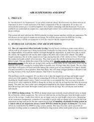
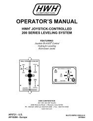
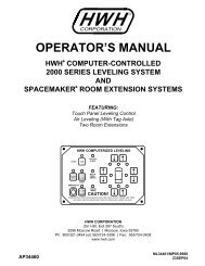
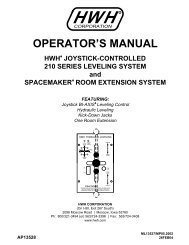
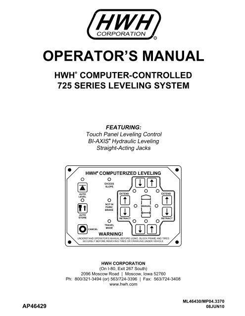
OPERATOR’S MANUAL<br />
<strong>HWH</strong> COMPUTER-CONTROLLED<br />
725 SERIES LEVELING SYSTEM<br />
R<br />
<strong>HWH</strong> CORPORATION<br />
R<br />
FEATURING:<br />
Touch Panel Leveling Control<br />
R<br />
BI-AXIS Hydraulic Leveling<br />
Straight-Acting Jacks<br />
R<br />
<strong>HWH</strong> COMPUTERIZED LEVELING<br />
EXCESS<br />
SLOPE<br />
AUTO<br />
LEVEL<br />
EXTEND<br />
EXTEND<br />
NOT IN<br />
PARK/<br />
BRAKE<br />
MANUAL<br />
AUTO<br />
STORE<br />
RETRACT<br />
RETRACT<br />
TRAVEL<br />
MODE<br />
CANCEL<br />
WARNING!<br />
UNDERSTAND OPERATOR’S MANUAL BEFORE USING. BLOCK FRAME AND TIRES<br />
SECURELY BEFORE REMOVING TIRES OR CRAWLING UNDER VEHICLE.<br />
<strong>HWH</strong> CORPORATION<br />
(On I-80, Exit 267 South)<br />
2096 Moscow Road | Moscow, Iowa 52760<br />
Ph: 800/321-3494 (or) 563/724-3396 | Fax: 563/724-3408<br />
www.hwh.com<br />
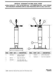
AP46429<br />
<strong>ML46430</strong>/MP04.3370<br />
08JUN10
OPERATING MANUAL<br />
WARNING !<br />
READ THE ENTIRE OPERATOR’S MANUAL BEFORE OPERATING.<br />
BLOCK FRAME AND TIRES SECURELY BEFORE CRAWLING UNDER VEHICLE. DO NOT USE LEVELING JACKS<br />
OR AIR SUSPENSION TO SUPPORT VEHICLE WHILE UNDER VEHICLE OR CHANGING TIRES. VEHICLE MAY<br />
DROP AND/OR MOVE FORWARD OR BACKWARD WITHOUT WARNING CAUSING INJURY OR DEATH.<br />
KEEP ALL PEOPLE CLEAR OF VEHICLE WHILE LEVELING SYSTEM, ROOM EXTENSIONS AND OTHER<br />
MOVABLE MECHANISMS ARE BEING OPERATED.<br />
NEVER PLACE HANDS OR OTHER PARTS OF THE BODY NEAR HYDRAULIC LEAKS. OIL MAY PENETRATE<br />
SKIN CAUSING INJURY OR DEATH.<br />
WEAR SAFETY GLASSES WHEN INSPECTING OR SERVICING THE SYSTEM TO PROTECT EYES FROM DIRT,<br />
METAL CHIPS, OIL LEAKS, ETC. FOLLOW ALL OTHER APPLICABLE SHOP SAFETY PRACTICES.<br />
IMPORTANT: IF COACH IS EQUIPPED WITH A ROOM EXTENSION, READ ROOM EXTENSION SECTION BEFORE<br />
OPERATING LEVELING SYSTEM.<br />
HOW TO OBTAIN WARRANTY SERVICE<br />
THIS IS NOT TO BE INTERPRETED AS A STATEMENT OF WARRANTY<br />
<strong>HWH</strong> CORPORATION strives to maintain the highest level of<br />
customer satisfaction. Therefore, if you discover a defect or<br />
problem, please do the following:<br />
FIRST: Notify the dealership where you purchased the<br />
vehicle or had the leveling system installed. Dealership<br />
management people are in the best position to resolve<br />
the problem quickly. If the dealer has difficulty solving<br />
the problem, he should immediately contact the Customer<br />
Service Department, at <strong>HWH</strong> CORPORATION.<br />
SECOND: If your dealer cannot or will not solve the problem,<br />
notify the Customer Service Department:<br />
<strong>HWH</strong> CORPORATION 2096 Moscow Rd. Moscow IA. 52760<br />
(563) 724-3396 OR (800) 321-3494. Give your name and<br />
address, coach manufacturer and model year, date the<br />
coach was purchased, or the date of system installation,<br />
authorization of an independent service facility, to be<br />
defective part, either by appointment at the factory or by the<br />
CORPORATION will authorize repair or replacement of the<br />
determine whether or not your claim is valid. If it is, <strong>HWH</strong><br />
<strong>HWH</strong> CORPORATION personnel will contact you to<br />
during business hours (8:00 a.m. till 5:00 p.m. c.s.t.).<br />
description of the problem, and where you can be reached<br />
determined by <strong>HWH</strong> CORPORATION. All warranty repairs<br />
must be performed by an independent service facility<br />
authorized by <strong>HWH</strong> CORPORATION, or at the<br />
<strong>HWH</strong> CORPORATION factory, unless prior written approval<br />
has been obtained from proper <strong>HWH</strong> CORPORATION<br />
personnel.<br />
MP14.0004<br />
17APR12
R<br />
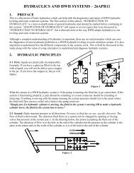
CONTROL IDENTIFICATION<br />
725 SERIES LEVELING SYSTEM<br />
COMPUTER-CONTROL<br />
AUTO LEVEL<br />
Indicator light<br />
"AUTO LEVEL"<br />
Button<br />
"NOT IN PARK"<br />
Indicator light<br />
STORE<br />
Indicator light<br />
AUTO<br />
LEVEL<br />
"EXCESS SLOPE"<br />
Indicator light<br />
<strong>HWH</strong> COMPUTERIZED LEVELING<br />
EXCESS<br />
SLOPE<br />
NOT IN<br />
PARK/<br />
BRAKE<br />
EXTEND<br />
MANUAL<br />
EXTEND<br />
LOWER FRONT<br />
Manual button<br />
RAISE FRONT<br />
Manual button<br />
JACK DOWN<br />
Indicator light<br />
(4) red<br />
RAISE RIGHT SIDE<br />
Manual button<br />
"AUTO STORE"<br />
Button<br />
AUTO LEVEL/STORE<br />
"CANCEL" Button<br />
"TRAVEL MODE"<br />
Indicator light<br />
AUTO<br />
STORE<br />
CANCEL<br />
RAISE LEFT SIDE<br />
Manual button<br />
LOWER LEFT SIDE<br />
Manual button<br />
TRAVEL<br />
MODE<br />
WARNING!<br />
RETRACT<br />
RETRACT<br />
UNDERSTAND OPERATOR’S MANUAL BEFORE USING. BLOCK FRAME AND TIRES<br />
SECURELY BEFORE REMOVING TIRES OR CRAWLING UNDER VEHICLE.<br />
LOWER RIGHT SIDE<br />
Manual button<br />
LEVEL SENSING<br />
Indicator light<br />
(4) yellow<br />
RAISE REAR<br />
Manual button<br />
LOWER REAR<br />
Manual button<br />
CONTROL FUNCTIONS<br />
"AUTO LEVEL" BUTTON: Push this button any time to<br />
start the automatic leveling function.<br />
"AUTO STORE" BUTTON:<br />
four jacks at the same time.<br />
EXTEND BUTTONS (UP ARROWS): These buttons will<br />
extend their respective jack pairs to lift the vehicle.<br />
RETRACT BUTTONS (DOWN ARROWS): These buttons<br />
will retract their respective jack pairs to lower the vehicle.<br />
AUTO LEVEL INDICATOR LIGHT: This light will flash<br />
during the automatic leveling function.<br />
STORE INDICATOR LIGHT:<br />
the automatic store function.<br />
CONTROL BUTTONS<br />
"CANCEL" BUTTON: Push this button to stop<br />
any leveling system operation.<br />
Push this button to retract all<br />
INDICATOR LIGHTS<br />
This light will flash during<br />
WARNING LIGHTS: The four red lights surrounding the<br />
yellow level indicators are jacks down WARNING lights.<br />
They are functional only when the ignition is in the "ON"<br />
or "ACC" position, the system is on, and the jacks are<br />
extended 1/4 to 1/2 inch.<br />
INDICATOR LIGHTS (CONTINUED)<br />
LEVELING LIGHTS: The four yellow indicating lights are<br />
level sensing indicators. When a yellow light is on, it<br />
indicates that its side, end, or corner of the vehicle is low.<br />
No more than two lights should be on at the same time.<br />
When all four yellow LEVEL lights are out, the vehicle is<br />
level.<br />
"EXCESS SLOPE" LIGHT: This indicator will light when<br />
the leveling system cannot level the vehicle.<br />
"NOT IN PARK/BRAKE" LIGHT: This indicator will light<br />
when the hand/auto brake is not set and the "AUTO LEVEL"<br />
button is being pushed.<br />
"TRAVEL MODE" LIGHT: This indicator light will be on<br />
when the ignition is on, when the jacks are retracted and<br />
there are no red WARNING lights on.<br />
MASTER "JACKS DOWN" WARNING LIGHT: This is a<br />
light mounted in the dash separate from the touch panel.<br />
It will be on when any one or more jacks are extended<br />
and the ignition is "ON".<br />
BUZZER: This is a jacks down warning. It will sound if the<br />
master "JACKS DOWN" warning light is on.<br />
MP24.3150<br />
17FEB11
CONTROL IDENTIFICATION<br />
PUMP RUN TIME<br />
SYSTEM VARIATIONS FOR PUMP RUN TIME<br />
PUMP RUN TIME<br />
Pump motors used with <strong>HWH</strong> leveling systems and room extension systems come in 3 different diameters; 3", 3.7" and 4.5".<br />
Contact the vehicle manufacturer or <strong>HWH</strong> for help with identifying the motor size. It is important that any time the pump<br />
runs for more than four minutes with a 3" motor; or six minutes with a 3.7" or 4.5" motor that the motor is allowed<br />
to cool for thirty minutes before continuing. Continuous operation of the pump motor without allowing the motor<br />
to cool can damage the motor. For cold weather information see "COLD WEATHER OPERATIONS" below.<br />
The <strong>HWH</strong> systems with a computer processor monitor the pump run time and will turn the pump off if the run time exceeds a<br />
specified time. This time can vary with different systems. Due to available electronics or system design, the pump run time<br />
programs will also vary. Leveling systems and room extensions that are not controlled by a system processor have no pump<br />
run time protection. DO NOT run the pump more than four or six minutes without allowing the pump motor to cool for<br />
thirty minutes.<br />
Some systems with rooms run the rooms separate from the system processor. These systems do not monitor pump<br />
run time when operating the rooms. DO NOT run the pump more than four or six minutes without allowing the<br />
pump motor to cool for thirty minutes.<br />
Some systems can be turned back on immediately after the processor turns the pump off. DO NOT turn the system<br />
back on or run the pump without allowing the pump motor to cool for thirty minutes.<br />
When operating some leveling systems manually or operating the room extensions, the pump will turn off and back<br />
on while pushing the control button when the pump run time has been exceeded. DO NOT continue without allowing<br />
the pump motor to cool for thirty minutes.<br />
With some systems, when the processor has turned the pump off because the run time has been exceeded, power<br />
to the <strong>HWH</strong> system must be turned off and back on before the system will operate. With motorized vehicles, turn the<br />
ignition off and back on. With non-motorized vehicles, turn the master power switch for the <strong>HWH</strong> system off and back<br />
on. DO NOT continue without allowing the pump motor to cool for thirty minutes.<br />
Some <strong>HWH</strong> systems are equipped with a lighted reset switch.<br />
If the processor turns the pump off because the run time has<br />
been exceeded, the light in the reset switch will turn on. The<br />
system will not operate until the reset switch is pushed.<br />
DO NOT continue without allowing the pump motor to<br />
cool for thirty minutes.<br />
LIGHTED RESET SWITCH<br />
No matter what <strong>HWH</strong> system is on the vehicle, the pump should not be ran for more than four minutes<br />
(3" motors) or six minutes (3.7" or 4.5" motors) without allowing the pump motor to cool for thirty minutes.<br />
Continuous operation of the pump motor without allowing the motor to cool can damage the pump motor.<br />
Contact <strong>HWH</strong> corporation to get specific information about the system in this vehicle.<br />
COLD WEATHER OPERATIONS<br />
<strong>HWH</strong> leveling and room extension systems are designed to function in cold weather down to 0 degrees Fahrenheit. Below<br />
freezing (32 degrees Fahrenheit) the jacks or rooms will operate slower than usual.<br />
For operation in temperatures dropping below -20 degrees Fahrenheit, it is necessary that the system is equipped with oil<br />
designed for extreme cold weather application such as a synthetic oil. (Contact <strong>HWH</strong> for recommendations.)<br />
DO NOT run the pump motor continuously. It is important that any time the pump runs for more than four minutes<br />
with a 3" motor; or six minutes with a 3.7" or 4.5" motor that the motor is allowed to cool for thirty minutes before<br />
continuing. Continuous operation of the pump motor without allowing the motor to cool can damage the motor.<br />
Continuous operation of the pump with slow moving jacks or rooms in cold weather, without allowing the pump motor to<br />
cool will cause the pump motor to burn up and damage the pump assembly.<br />
MP25.9995<br />
14MAR12
OPERATING PROCEDURES<br />
GENERAL INSTRUCTIONS<br />
Maintain adequate clearance in all directions for vehicle, room<br />
extensions, awnings, doors, steps, etc. Vehicle may move in<br />
any direction due to jacks extending or retracting, settling of<br />
the jacks or the vehicle, equipment malfunction, etc..<br />
If parking on soft ground or asphalt paving, a wood block or<br />
pad should be placed under each jack.<br />
Press the "CANCEL" button or turn the ignition switch<br />
"OFF" at any time to stop the operation of the system.<br />
If the hand / auto brake is not set when the "AUTO LEVEL"<br />
button is pressed, the "NOT IN PARK/BRAKE" light will<br />
come on. When the "AUTO LEVEL" button is released the<br />
"NOT IN PARK/BRAKE" light will go out. The Automatic<br />
Leveling function will not start.<br />
WARNING: DO NOT MOVE THE VEHICLE IF ONE<br />
OR MORE JACKS ARE EXTENDED TO THE GROUND.<br />
Any time a hydraulic leveling process is interrupted, it is<br />
recommended to retract the jacks according to the JACK<br />
RETRACTION Section and then restart the leveling process.<br />
PREPARATION FOR TRAVEL<br />
IMPORTANT: Before traveling, the red jack warning<br />
lights must be off and the "TRAVEL MODE" light must<br />
be on. If lights are not correct for travel, retract jack as<br />
described in the JACK RETRACTION Section.<br />
If the jacks are retracted but a red "WARNING" light is lit<br />
the system needs to be serviced.<br />
Any room extension or generator slide should be fully<br />
retracted before traveling.<br />
WARNING: DO NOT MOVE THE VEHICLE WHILE<br />
THE LEVELING JACKS ARE STILL IN CONTACT WITH<br />
THE GROUND OR IN THE EXTEND POSITION. THIS<br />
VEHICLE IS EQUIPPED WITH STRAIGHT-ACTING JACKS.<br />
MOVING THE VEHICLE WITH THE LEVELING JACKS<br />
EXTENDED CAN CAUSE SEVERE DAMAGE TO THE<br />
JACKS AND OR THE VEHICLE AND CREATE A DRIVING<br />
HAZARD. DO NOT RELY SOLELY UPON WARNING<br />
LIGHTS. IT IS THE OPERATOR’S RESPONSIBILITY TO<br />
CHECK THAT ALL JACKS ARE FULLY RETRACTED<br />
INTO THE STORE/TRAVEL POSITION.<br />
If the jacks cannot be retracted according to the JACK<br />
RETRACTION Section, retract the jacks according to the<br />
MANUAL JACK RETRACTION Section. The system<br />
should then be checked.<br />
NOTE: If the vehicle is parked or stored with the jacks<br />
extended for an extended period of time and the jacks<br />
fail to retract completely, extend the jacks back down<br />
to the ground then retract the jacks again.<br />
MP34.0229<br />
06AUG13
OPERATING PROCEDURES<br />
725 SERIES LEVELING SYSTEM<br />
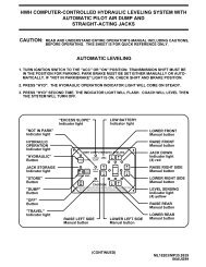
AUTOMATIC HYDRAULIC LEVELING<br />
1. Place transmission in the recommended position for<br />
parking the vehicle and set parking brake. Turn the coach<br />
engine off. Turn the ignition to the "ACCESSORY" position.<br />
NOTE: One or two yellow level indicator lights on<br />
the leveling system touch panel can be on anytime<br />
the vehicle ignition is in the ON or ACC. position<br />
and the park brake is set.<br />
2. At this time, the operator may want to check the jacks<br />
and place a pad under each jack if the ground will not<br />
support the vehicle.<br />
3. Press the "AUTO LEVEL" button one time.<br />
The AUTO LEVEL light will start to flash.<br />
IMPORTANT: During the Automatic Leveling procedures,<br />
pushing the "AUTO LEVEL", "AUTO STORE" or the<br />
"CANCEL" button on the <strong>HWH</strong> touch panel will stop<br />
the automatic leveling function.<br />
AUTO LEVEL SEQUENCE: During the automatic<br />
leveling sequence, after the system has extended the<br />
appropriate jacks to level the vehicle and has turned<br />
the yellow level indicator lights off, the system will<br />
then stabilize the vehicle.<br />
Stabilize sequence information: The stabilize sequence<br />
is part of the auto level sequence. Each jack has a pressure<br />
switch. The switch will turn on when the jack extends to the<br />
ground and lifts the vehicle slightly. Jacks that have lifted the<br />
vehicle for leveling should have pressure switches that are<br />
on.<br />
The stabilize procedure is a specific sequence where the<br />
computer checks the jack pressure switches. If the switch<br />
is on, the jack is stabilizing the vehicle. If the switch is not<br />
on, the computer turns the pump and valve on for that jack<br />
until the pressure switch turns on.<br />
If at this time a yellow level light is on, the system will<br />
automatically repeat the leveling sequence. The repeat<br />
sequence will only happen if a yellow level light is on at the<br />
end of the initial leveling and stabilizing sequence.<br />
If a yellow level light is still on after the repeat sequence,<br />
the system will turn off, leaving the level light on.<br />
The slight lift experienced during the stabilizing procedure<br />
normally is not sufficient to cause a level issue for the motor<br />
home. However, a feature of the single step leveling system<br />
is the manual leveling buttons will function anytime the<br />
ignition is in the ON or ACC. position and the park brake is<br />
set. If desired, the operator can use the UP ARROWS<br />
(extend jacks) that correspond to any lit yellow level indicator<br />
light to "bump" the vehicle up slightly to turn that yellow<br />
indicator light off.<br />
EXCESS SLOPE SITUATION: In the event the jacks are<br />
unable to level the coach, the "EXCESS SLOPE" light will<br />
come on. Excess slope is one or two jacks fully extended<br />
without turning the yellow level light out. The system will not<br />
stabilize the vehicle if the "EXCESS SLOPE" light comes on.<br />
One or more jacks may be extended. The system will shut<br />
off leaving the "EXCESS SLOPE" light on. The "EXCESS<br />
SLOPE" light will remain on if there is power to the control<br />
box, until the jacks have been fully retracted using the<br />
"STORE" button, turning the red warning lights out. Refer<br />
to the HITCHING AND STORING JACKS section. Move<br />
the trailer to a more level position or level the trailer as close<br />
as possible according to the MANUAL LEVELING section.<br />
Manual leveling will operate when the EXCESS SLOPE<br />
light is on.<br />
5. Turn the ignition switch to the "OFF" position.<br />
The sequence starts with the right rear jack. If the pressure<br />
switch is not on, the system will extend the jack as necessary.<br />
If the switch is on (or when it comes on) the system will check<br />
the left rear jack pressure switch, extending the jack if necessary<br />
If the left rear switch is on (or when it comes on), the system<br />
will recheck the right rear (extending if necessary) then recheck<br />
the left rear (extending if necessary). After checking and<br />
rechecking both rear jacks, the system then checks the front<br />
jacks. The system checks both front jacks at the same time.<br />
If either pressure switch is not on, the system will turn the<br />
pump on and open the valves for both front jacks. When<br />
both front pressure switches are on, the system turns the<br />
pump and front valves off.<br />
MP34.2752<br />
06AUG13
OPERATING PROCEDURES<br />
725 SERIES LEVELING SYSTEM<br />
JACK RETRACTION (<strong>HWH</strong> TOUCH PANEL CONTROLS)<br />
WARNING: THE OPERATOR MUST BE SURE THAT<br />
THERE ARE NO OBJECTS UNDER THE VEHICLE AND THAT<br />
ALL PEOPLE ARE CLEAR OF THE VEHICLE.<br />
NOTE: When the jacks are stored with the ignition in<br />
the ON position, the warning buzzer will sound until<br />
the jacks have retracted to the STORE position. If<br />
desired, the jacks can be stored with the ignition key<br />
in the accessory position. This will eliminate the<br />
warning buzzer while the jacks are retracting.<br />
1. Press the "AUTO STORE" button. The store indicator<br />
light will flash. The front jacks will retract for 5 seconds<br />
before the rear jacks will begin to retract. As each jack<br />
retracts, its red WARNING light will go out. The system<br />
will automatically shut down 1 minute after the four<br />
individual red "WARNING" lights are out. If any one red<br />
"WARNING light does not go out, the system will continue<br />
to store for fifty minutes, then shut down regardless of<br />
the "WARNING" lights condition.<br />
NOTE: When traveling thermal expansion may cause<br />
a jack to extend slightly. When the "AUTO STORE"<br />
button has been used to retract the jacks, the system<br />
will automatically retract any jack that extends due to<br />
thermal expansion.<br />
IMPORTANT: If power to the system is interrupted after<br />
starting a store procedure the store procedure should be<br />
reinitiated and the jacks should be completely retracted<br />
with all four red WARNING lights out prior to traveling.<br />
IMPORTANT: During the Automatic Store procedures,<br />
pushing the "AUTO LEVEL", "AUTO STORE" or the<br />
"CANCEL" button on the <strong>HWH</strong> touch panel will stop<br />
the automatic store function.<br />
WARNING: DO NOT MOVE THE VEHICLE WHILE THE<br />
LEVELING JACKS ARE STILL IN CONTACT WITH THE GROUND<br />
OR IN THE EXTEND POSITION. THIS VEHICLE IS EQUIPPED<br />
WITH STRAIGHT-ACTING JACKS. MOVING THE VEHICLE<br />
WITH THE LEVELING JACKS EXTENDED CAN CAUSE<br />
SEVERE DAMAGE TO THE JACKS AND OR THE VEHICLE AND<br />
CREATE A DRIVING HAZARD. DO NOT RELY SOLELY UPON<br />
WARNING LIGHTS. IT IS THE OPERATOR’S RESPONSIBILITY TO<br />
CHECK THAT ALL JACKS ARE FULLY RETRACTED INTO<br />
THE STORE/TRAVEL POSITION.<br />
2. The vehicle can be moved as soon as the red warning<br />
lights are out, the jacks are in the STORE/TRAVEL position<br />
and the green "TRAVEL" light is on.<br />
IMPORTANT: If a red warning light and buzzer come on<br />
while traveling, the jacks should be checked as soon as<br />
a safe parking location is found.<br />
3. If jacks cannot be retracted by the above procedure see<br />
MANUAL JACK RETRACTION Section.<br />
MP34.3062<br />
08JUN10
OPERATING PROCEDURES<br />
MANUAL HYDRAULIC OPERATION<br />
1. Place transmission in the recommended position for parking<br />
the vehicle, and set the parking brake. Turn the ignition to the<br />
"ACCESSORY" position.<br />
2. Place pads under the jack feet if the ground will not support<br />
the vehicle on the jacks.<br />
3. The vehicle may be leveled using the manual EXTEND<br />
(UP ARROW) buttons on the right half of the panel. If a yellow<br />
LEVEL SENSING light is on, that side, end or corner of the<br />
vehicle is low. It is best to level the vehicle side to side first,<br />
if needed, before front to rear.<br />
Any jack not used for leveling can be extended to the<br />
ground. This provides additional stability against wind and<br />
activity in the vehicle. Jacks used to stabilize the vehicle<br />
after leveling is complete should lift the vehicle slightly after<br />
touching the ground.<br />
IMPORTANT: Do not continue to push an EXTEND<br />
button for more than ten (10) seconds after that pair of<br />
jacks are fully extended.<br />
4. When leveling is completed, turn the ignition<br />
switch to the "OFF" position.<br />
Jacks will extend (or retract) in pairs to raise (or lower) a side<br />
or end of the vehicle.<br />
MANUAL JACK RETRACTION<br />
The solenoid valves on the power unit valve assembly are<br />
equipped with a manual valve release. Use the manual valve<br />
release for retracting only if the "AUTO STORE" button on the<br />
control panel will not retract the jacks for travel.<br />
NOTE: Assemblies can have different combinations of<br />
large and / or small valves.<br />
WARNING:<br />
KEEP AWAY FROM THE WHEELS,<br />
DO NOT CRAWL UNDER THE VEHICLE, KEEP A SAFE<br />
DISTANCE IN FRONT AND REAR OF THE VEHICLE.<br />
THE VEHICLE MAY DROP AND/OR MOVE FORWARD<br />
OR BACKWARD WITHOUT WARNING AS THE VALVE<br />
RELEASE IS OPERATED.<br />
1. Locate the manual valve release on each solenoid valve.<br />
The solenoid valves are located on the power unit/valve<br />
assembly.<br />
2. Allow clearance for the vehicle to lower.<br />
IMPORTANT: Only open the valves enough to retract<br />
the jacks. DO NOT turn valve release nuts on the small<br />
valves more than 4 and 1/2 turns. Turning the nuts more<br />
could damage the valves.<br />
Large valves with valve release nuts will need the<br />
release nut turned approximately 2 full turns. More<br />
than 2 full turns may damage the valve.<br />
Large and small valves may be equipped with a valve<br />
release cam. The cam might be rotated in any direction<br />
on the valve. Pushing the release cam in the wrong<br />
direction may damage the valve.<br />
4. Repeat the process for the rear jacks by opening the two<br />
outer valves.<br />
A 1/4" Nut Driver has been incorporated into the Breather<br />
Cap. See the back page of this manual for further info.<br />
5. Check that all four jacks are now retracted.<br />
6. Close the valves by turning the manual valve releases<br />
clockwise, or move the valve release cam to the closed<br />
position.<br />
IMPORTANT: Once the valve release nut is snug, DO<br />
NOT tighten the valve release nut past this point as<br />
internal damage may occur to the solenoid.<br />
7. The system should now be repaired before using again.<br />
MANIFOLD<br />
OPEN<br />
VALVE RELEASE CAM OPERATION<br />
VALVE<br />
CLOSED<br />
CLOSE<br />
VALVE<br />
OPENED<br />
LARGE STYLE WITH<br />
VALVE RELEASE CAM<br />
SMALL STYLE<br />
WITH VALVE<br />
RELEASE CAM<br />
BREATHER<br />
CAP<br />
3. Retract the front jacks by slowly opening<br />
the two center valves.<br />
LARGE STYLE WITH<br />
VALVE RELEASE NUT<br />
PLASTIC PLUG<br />
SMALL STYLE WITH<br />
VALVE RELEASE NUT<br />
MP34.3334<br />
08JUN10
MAINTENANCE<br />
OIL LEVEL<br />
All maintenance should be done as part of the normal<br />
servicing of the coach.<br />
The oil level should be checked when the vehicle is first<br />
purchased and then once every two years. More often if<br />
there is an oil leak in the system.<br />
All jacks and any <strong>HWH</strong> room extensions or steps should be<br />
completely retracted before checking the oil level. The oil<br />
reservoir is part of the pump / manifold assembly. The oil<br />
level is checked and filled through the breather cap. Clear<br />
any dirt away from the breather / filler cap before removing.<br />
The oil level should be within one inch of the top of the<br />
reservoir. Most breather caps have a dipstick.<br />
NOTE: Overfilling the tank can cause leakage of oil<br />
through the breather cap.<br />
FLUID: <strong>HWH</strong> Specialty Hydraulic Oil is recommended. In an<br />
emergency Dexron automatic transmission fluid can be used.<br />
NOTE: Dexron automatic transmission fluid contains red dye<br />
and can cause staining should a leak occur. DO NOT USE<br />
brake fluid or hydraulic jack fluid. Use of these can damage<br />
seals.<br />
ELECTRICAL SYSTEM<br />
The batteries should be in good condition and fully charged.<br />
Weak batteries can cause erratic operation. Battery cable<br />
terminals and battery posts and connections should be kept<br />
clean.<br />
All electrical connections, especially ground connections,<br />
should be clean, tight, free from corrosion and protected<br />
from weathering.<br />
JACKS<br />
There are very few user serviceable parts on the jacks<br />
The jacks require very little maintenance. If the jacks are<br />
extremely dirty with caked on mud they should be washed.<br />
If extremely dirty, the jack rods should NOT be wiped. The<br />
jack rods do not need to be oiled or sprayed with anything.<br />
See ML47149 for proper maintenance of all jacks.<br />
ROOM EXTENSIONS<br />
The <strong>HWH</strong> room mechanisms need no maintenance.<br />
DO NOT grease or lubricate any parts of the <strong>HWH</strong><br />
mechanism.<br />
Any visible mechanism can be kept clean by washing<br />
with water. Refer to the vehicle manufacturer for<br />
correct maintenance of the room seals.<br />
VISUAL INSPECTION<br />
Periodically inspect the system for oil leaks and<br />
damaged or missing parts, such as pivot bolts or springs.<br />
Check the hydraulic lines and wiring for damage and wear.<br />
Check that the jacks do not interfere with any parts of the<br />
vehicle when they are in the "STORE" position.<br />
The system will operate better if kept clean and free<br />
from caked on mud or ice.<br />
OPERATIONAL CHECK<br />
Review the OPERATOR MANUAL. Run the system<br />
according to the SYSTEM OPERATION Section.<br />
Note any abnormal operation.<br />
Check that all lights work according to the "INDICATOR<br />
LIGHT" Section. Correct function of the red "WARNING"<br />
light is important.<br />
Review the "JACK RETRACTION" Section. Make sure the<br />
jacks will fully retract to the "STORE" position. Jacks should<br />
not interfere with any of the coach when in the "STORE"<br />
position.<br />
MP44.0018<br />
10APR12
MAINTENANCE<br />
NOT IN PARK/BRAKE CHECK<br />
WARNING: WHEN MAKING THIS CHECK, BLOCK<br />
THE COACH WHEELS SECURELY SO THE COACH<br />
CANNOT ROLL FORWARD OR BACKWARD.<br />
Set the park/brake. Switch the ignition to the "ACC" or<br />
"ON" position. Push the"AUTO LEVEL" button. Release<br />
the parking brake and confirm that the "PARK" indicator<br />
light comes on. Reset the parking brake. The "PARK"<br />
indicator light should go out. Switch the ignition to "OFF".<br />
If any of the above checks or inspections reveal a problem<br />
or if there are other problems or questions, consult a<br />
qualified RV repair center, your vehicle or coach<br />
manufacturer, or <strong>HWH</strong> CORPORATION<br />
for service or repair.<br />
MP44.0502<br />
08APR10
INSTRUCTION SHEET<br />
SENSING UNIT MAINTENANCE/SERVICE<br />
REMOTE MOUNTED "POTTED" ELECTRONIC SENSING UNIT<br />
SENSING UNIT ACCURACY TOLERANCE<br />
The sensing unit has an accuracy tolerance of ± 5.4 inches front to rear and<br />
± 1 inch side to side on a 36 foot vehicle. Typical leveling results will be better.<br />
SENSING UNIT ADJUSTMENT / WITHOUT ADJUSTING ENHANCEMENT<br />
Level the vehicle by placing a bubble level in the center of the<br />
freezer floor or upon whichever surface within the vehicle that<br />
is to be level. It is best if the level is placed close to the<br />
mounting area of the sensing unit. Using the Leveling System<br />
and the bubble level, ignoring the yellow LEVEL lights on the<br />
Touch Panel, level the vehicle until the bubble is centered.<br />
With the vehicle level according to the bubble level, if there<br />
are no yellow lights lit on the Touch Panel, the sensing unit is<br />
properly adjusted. If there are yellow LEVEL lights lit on the<br />
Touch Panel, manual adjustments to the Sensing Unit are<br />
needed. Tighten or loosen the adjustment screws according<br />
to these instructions to adjust the sensing unit.<br />
IMPORTANT: THE SENSING UNIT MOUNTING SPRINGS<br />
SHOULD BE COMPRESSED ABOUT 1/2 THEIR FREE<br />
LENGTH. SCREW NUMBER 2 SHOULD NOT BE TURNED<br />
WHILE ADJUSTING THE SENSING UNIT. AFTER<br />
ADJUSTING THE SENSING UNIT, BUMP THE SENSING<br />
UNIT TO SEE THAT IT IS SETTLED TIGHT AGAINST ALL<br />
THREE SCREW HEADS AND STILL INDICATES THAT<br />
THE UNIT IS LEVEL.<br />
NOTE: If opposing LED’s are lit, there is a problem with<br />
the Sensing Unit.<br />
If LED (A) is lit: Tighten adjustment screw number 1<br />
until the LED is off.<br />
If LED (C) is lit: Loosen adjustment screw number 1<br />
until the LED is off.<br />
If LED (B) is lit: Loosen adjustment screw number 3<br />
until the LED is off.<br />
If LED (D) is lit: Tighten adjustment screw number 3<br />
until the LED is off.<br />
IMPORTANT: WHEN ALL 4 LED’S ARE OFF, MOVE THE<br />
VEHICLE TO AN UNLEVEL POSITION SO ONE OR TWO<br />
YELLOW LIGHTS ARE ON. LEVEL THE VEHICLE<br />
ACCORDING TO THE YELLOW LEVEL LIGHTS.<br />
RECHECK THE LEVEL. IF MORE ADJUSTMENT IS<br />
NEEDED, DO NOT TRY TO ADJUST THE SENSING UNIT<br />
UNTIL THE YELLOW LEVEL LIGHTS GO OUT, INSTEAD<br />
JUST "TWEAK" THE SENSING UNIT, IGNORING THE<br />
LED’S ON THE SENSING UNIT.<br />
LED<br />
D<br />
3<br />
LED<br />
A<br />
LED<br />
C<br />
LED A - FRONT OF VEHICLE<br />
LED B - LEFT SIDE OF VEHICLE<br />
LED C - REAR OF VEHICLE<br />
LED D - RIGHT SIDE OF VEHICLE<br />
LED<br />
B<br />
1<br />
2<br />
MOUNTING/ADJUSTMENT<br />
SCREWS (3)<br />
YELLOW LEDs<br />
Example: After the initial adjustment and releveling<br />
the vehicle, the front is still low. This means the front<br />
yellow level light is turning off too soon. LED A is for<br />
the front of the vehicle. Move the adjustment for that<br />
light very, very, slightly in the OPPOSITE direction that<br />
is given in the above instructions for LED’s A, B, C<br />
and D. This will allow the front yellow light to stay<br />
on slightly longer to bring the front up more. Again,<br />
unlevel the vehicle then relevel the vehicle using<br />
the yellow level lights on the touch panel. Recheck<br />
with a level. Repeat the "tweaking" process until the<br />
system levels the vehicle properly.<br />
(3) MOUNTING<br />
SPRINGS<br />
(3) MOUNTING<br />
SCREWS<br />
MOUNTED BELOW<br />
MOUNTING SURFACE<br />
BOTTOM VIEW OF<br />
SENSING UNIT<br />
FRONT<br />
THIS<br />
SIDE<br />
UP<br />
MP44.1510<br />
09NOV10
INSTRUCTION SHEET<br />
SENSING UNIT MAINTENANCE/SERVICE<br />
REMOTE MOUNTED "POTTED" ELECTRONIC SENSING UNIT<br />
SENSING UNIT ACCURACY TOLERANCE<br />
The sensing unit has an accuracy tolerance of ± 5.4 inches front to rear and<br />
± 1 inch side to side on a 36 foot vehicle. Typical leveling results will be better.<br />
SENSING UNIT ADJUSTMENT / WITH ADJUSTING ENHANCEMENT<br />
Level the vehicle by placing a bubble level in the center of the<br />
freezer floor or upon whichever surface within the vehicle that<br />
is to be level. It is best if the level is placed close to the<br />
mounting area of the sensing unit. Using the Leveling System<br />
and the bubble level, ignoring the yellow LEVEL lights on the<br />
Touch Panel, level the vehicle until the bubble is centered.<br />
With the vehicle level according to the bubble level, if there<br />
are no yellow lights lit on the Touch Panel, the sensing unit is<br />
properly adjusted. If there are yellow LEVEL lights lit on the<br />
Touch Panel, manual adjustments to the Sensing Unit are<br />
needed.<br />
Move the vehicle to an unlevel position and level the<br />
vehicle according to the yellow level sensing lights on<br />
the touch panel. Readjust if necessary.<br />
IMPORTANT: THE SENSING UNIT MOUNTING SPRINGS<br />
SHOULD BE COMPRESSED ABOUT 1/2 THEIR FREE<br />
LENGTH. SCREW NUMBER 2 SHOULD NOT BE TURNED<br />
WHILE ADJUSTING THE SENSING UNIT. AFTER<br />
ADJUSTING THE SENSING UNIT, BUMP THE SENSING<br />
UNIT TO SEE THAT IT IS SETTLED TIGHT AGAINST ALL<br />
THREE SCREW HEADS AND STILL INDICATES THAT<br />
THE UNIT IS LEVEL.<br />
The ignition (motorized units) or master power switch (towable<br />
units) must be on. Remove the "Adjusting Enhancement Cap".<br />
DO NOT LOSE THIS CAP. There is a small pin beneath the<br />
cap. Use a jumper wire with an alligator clip to apply a ground<br />
to the pin. This will make the sensing unit very sensitive. The<br />
yellow lights may "jump" around while adjusting the sensing unit.<br />
Let the lights settle down after each adjustment. Small, gentle<br />
turns will work best. Turn mounting screws 1 and 3 to adjust<br />
the sensing unit. Turn screws as instructed to turn out all the<br />
yellow LEDs. When all the LEDs are out, remove the jumper<br />
wire and replace the adjusting enhancement cap. DO NOT<br />
over tighten.<br />
LED A - FRONT OF VEHICLE<br />
LED B - LEFT SIDE OF VEHICLE<br />
LED C - REAR OF VEHICLE<br />
LED D - RIGHT SIDE OF VEHICLE<br />
NOTE: If opposing LED’s are lit, there is a problem with<br />
the Sensing Unit.<br />
If LED (A) is lit: Tighten adjustment screw number 1<br />
until the LED is off.<br />
If LED (C) is lit: Loosen adjustment screw number 1<br />
until the LED is off.<br />
If LED (B) is lit: Loosen adjustment screw number 3<br />
until the LED is off.<br />
If LED (D) is lit: Tighten adjustment screw number 3<br />
until the LED is off.<br />
LED<br />
D<br />
LED<br />
A<br />
LED<br />
C<br />
LED<br />
B<br />
1<br />
MOUNTING/ADJUSTMENT<br />
SCREWS (3)<br />
YELLOW LEDs<br />
(3) MOUNTING<br />
SPRINGS<br />
(3) MOUNTING<br />
SCREWS<br />
MOUNTED BELOW<br />
MOUNTING SURFACE<br />
3<br />
2<br />
ADJUSTING<br />
ENHANCEMENT<br />
CAP<br />
FRONT<br />
THIS<br />
SIDE<br />
UP<br />
BOTTOM VIEW OF<br />
SENSING UNIT<br />
MP44.1511<br />
09NOV10
HYDRAULIC LINE CONNECTION DIAGRAM<br />
625/725 SERIES LEVELING SYSTEM<br />
(WITH 4 STRAIGHT-ACTING JACKS)<br />
MANIFOLDS MAY HAVE FOUR (4) LARGE<br />
VALVES OR FOUR (4) SMALL VALVES<br />
NOTE: BEFORE OPERATING MANUAL<br />
VALVE RELEASE, READ AND UNDERSTAND<br />
PROCEDURE FOR MANUAL JACK RETRACTION<br />
IN OPERATOR’S INSTRUCTIONS. VALVES MAY<br />
BE EQUIPPED WITH VALVE RELEASE NUTS OR<br />
RELEASE CAMS.<br />
LEFT<br />
FRONT<br />
NOTE: Load center is<br />
not shown, load center<br />
may need to be removed<br />
to be removed to access<br />
shuttle valve and shuttle<br />
valve tube.<br />
LARGE AND<br />
SMALL VALVES<br />
WITH RELEASE<br />
NUTS<br />
CHECK<br />
PRESSURE<br />
HERE<br />
NOTE: SOME<br />
MANIFOLDS<br />
ARE EQUIPPED<br />
WITH VELOCITY<br />
VALVES<br />
LR<br />
BREATHER<br />
CAP<br />
LF<br />
RF<br />
RR<br />
LARGE AND<br />
SMALL VALVES<br />
WITH RELEASE<br />
CAMS<br />
OUTER<br />
CHECK<br />
VALVES (4)<br />
SHUTTLE<br />
VALVE<br />
50PSI<br />
PRESSURE<br />
SWITCH<br />
RIGHT<br />
FRONT<br />
ALTERNATE<br />
3000 PSI<br />
PRESSURE<br />
SWITCH<br />
LOCATION<br />
3000PSI<br />
PRESSURE<br />
SWITCH<br />
PUMP/MANIFOLD<br />
ASSEMBLY<br />
LEFT<br />
REAR<br />
VELOCITY VALVE<br />
RIGHT<br />
REAR<br />
MP64.3917<br />
01NOV11
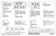
HYDRAULIC SCHEMATIC DIAGRAM<br />
BI-AXIS LEVELING WITH STRAIGHT-ACTING JACKS<br />
625, 625S OR 725 SERIES<br />
M<br />
RELIEF VALVE<br />
3500 P.S.I.<br />
NOTE: 50 PSI PRESSURE SWITCH<br />
MAY NOT BE USED ON ALL 625 MANIFOLDS.<br />
RETURN<br />
PRESSURE<br />
HYDRAULIC<br />
POWER UNIT<br />
ROOM EXTENSION<br />
MANIFOLD LOCATED HERE<br />
WHEN APPLICABLE<br />
LEVELING SYSTEM<br />
SOLENOID MANIFOLD<br />
ASSEMBLY<br />
*3000 PSI<br />
SWITCH<br />
PRESSURE/RETURN<br />
SHUTTLE VALVE<br />
800 PSI TO SHIFT<br />
50 PSI<br />
SWITCH<br />
CHECK<br />
VALVE<br />
INNER<br />
SOL.VALVE<br />
LR<br />
SOL.VALVE<br />
LF<br />
SOL.VALVE<br />
RF<br />
SOL.VALVE<br />
RR<br />
CHECK<br />
VALVE<br />
OUTER<br />
LEFT<br />
FRONT<br />
RIGHT<br />
FRONT<br />
*JACK<br />
PRESSURE<br />
SWITCH<br />
LEFT REAR<br />
JACK<br />
CYLINDER<br />
* USED ON AUTOMATIC SYSTEMS ONLY<br />
RIGHT REAR<br />
MP64.4530<br />
29MAR10
R<br />
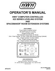
ELECTRICAL CONNECTION DIAGRAM<br />
725 SERIES SINGLE STEP LEVELING SYSTEM<br />
JACK WARNING SWITCHES, PRESSURE SWITCHES & PARK BRAKE<br />
LF<br />
PRESSURE<br />
SWITCH<br />
PRESSURE<br />
SWITCH<br />
RF<br />
WARNING<br />
SWITCH<br />
WARNING<br />
SWITCH<br />
B A<br />
B A<br />
6235<br />
2000<br />
1000<br />
6235<br />
1200 2200<br />
TOUCH PANEL<br />
<strong>HWH</strong> COMPUTERIZED LEVELING<br />
EXCESS<br />
SLOPE<br />
SEE ELECTRICAL CONNECTION DIAGRAM<br />
LEVELING SYSTEM HYDRAULIC MANIFOLD<br />
PUMP AND MASTER RELAYS<br />
AUTO<br />
LEVEL<br />
EXTEND<br />
EXTEND<br />
NOT IN<br />
PARK/<br />
MANUAL<br />
BRAKE<br />
AUTO<br />
STORE<br />
RETRACT<br />
RETRACT<br />
TRAVEL<br />
MODE<br />
CANCEL<br />
WARNING!<br />
UNDERSTAND OPERATOR’S MANUAL BEFORE USING. BLOCK FRAME AND TIRES<br />
SECURELY BEFORE REMOVING TIRES OR CRAWLING UNDER VEHICLE.<br />
SEE ELECTRICAL CONNECTION<br />
DIAGRAM - SENSING UNIT<br />
SEE ELECTRICAL CONNECTION DIAGRAM<br />
MASTER WARNING LIGHT AND BUZZER<br />
DO NOT CUT<br />
TERMINATING<br />
RESISTOR<br />
PARK BRAKE<br />
SWITCH<br />
DIODE<br />
9000<br />
NOTE: DIODE ARRANGEMENT MAY NOT BE<br />
PRESENT ON ALL INSTALLATIONS<br />
9001 - TO<br />
PARK BRAKE<br />
LIGHT<br />
DO NOT CUT<br />
TERMINATING<br />
RESISTOR<br />
8100<br />
8101<br />
FUSE<br />
15 AMP<br />
TO +12V ACC.<br />
SEE ELECTRICAL CONNECTION DIAGRAM<br />
MULTIPLEXED INPUT/OUTPUT MODULE<br />
PRESSURE SWITCH<br />
PRESSURE SWITCH<br />
LR<br />
WARNING<br />
SWITCH<br />
WARNING<br />
SWITCH<br />
RR<br />
B A B A<br />
6235<br />
3000<br />
4000<br />
6235<br />
4200 3200<br />
MP84.3111<br />
17JUN11
ELECTRICAL CONNECTION DIAGRAM<br />
MULTIPLEXED INPUT/OUTPUT MODULE<br />
LED AND WIRE/CONNECTION INFORMATION<br />
NOTE: DUMP AND TRAVEL LEDS PRESENT<br />
BUT NOT ALWAYS USED<br />
RIGHT REAR JACK<br />
RIGHT FRONT JACK<br />
LEFT FRONT JACK<br />
LEFT REAR JACK<br />
LINK LIGHT<br />
PUMP RELAY<br />
MASTER RELAY<br />
GROUND STUD<br />
DUMP<br />
TRAVEL<br />
FRONT VIEW<br />
OF I/O<br />
MODULE<br />
CONNECTOR<br />
8 7 6 5 4 3 2 1<br />
A<br />
B<br />
C<br />
D<br />
A LIT RED LED INDICATES THERE SHOULD BE<br />
+12 VOLTS ON THE CORRESPONDING WIRE.<br />
LINK LIGHT: LINK LIGHT FLASHING INDICATES PROPER<br />
COMMUNICATION BETWEEN THE I/O MODULE AND THE<br />
TOUCH PANEL. LINK LIGHT ON SOLID OR OFF INDICATES<br />
A FAILURE.<br />
PIN #<br />
WIRE<br />
COLOR<br />
WIRE<br />
NUMBER<br />
WIRE DESCRIPTION AND FUNCTION<br />
A1 - (+12 BLACK WIRE 8601) INPUT WHEN EXTENSION DEVICES ROOMS, GEN SLIDE, STEP COVER ECT. ARE USED<br />
A2 YELLOW<br />
N/A<br />
CAN HIGH COMMUNICATION WIRE<br />
A3 AND A4<br />
NO CONNECTION<br />
A5 BLACK<br />
2000<br />
SWITCHED GROUND FROM RIGHT FRONT JACK WARNING SWITCH<br />
A6 BLACK<br />
2200<br />
SWITCHED GROUND FROM RIGHT FRONT JACK PRESSURE SWITCH<br />
A7 BLACK<br />
3200<br />
SWITCHED GROUND FROM RIGHT REAR JACK PRESSURE SWITCH<br />
A8 BLACK<br />
8101<br />
SWITCHED GROUND FROM 50 PSI MANIFOLD PRESSURE SWITCH<br />
B1 RED<br />
6800<br />
+12 VOLT POWER TO THE TOUCH PANEL<br />
B2 GREEN<br />
N/A<br />
CAN LOW COMMUNICATION WIRE<br />
B3 WHITE<br />
6230<br />
GROUND TO THE TOUCH PANEL<br />
B4<br />
NO CONNECTION<br />
B5 BLACK<br />
3000<br />
SWITCHED GROUND FROM RIGHT REAR JACK WARNING SWITCH<br />
B6 BLACK<br />
4200<br />
SWITCHED GROUND FROM LEFT REAR JACK PRESSURE SWITCH<br />
B7<br />
NO CONNECTION<br />
B8 BLACK<br />
8100<br />
SWITCHED GROUND FROM 3000 PSI MANIFOLD PRESSURE SWITCH<br />
C1 RED 6121<br />
+12 VOLT POWER FOR LEVEL SENSING UNIT<br />
C2 N/A<br />
N/A<br />
SHIELD WIRE FOR GREEN & YELLOW CAN COMMUNICATION WIRES<br />
C3 WHITE<br />
6231<br />
GROUND FOR LEVEL SENSING UNIT<br />
C4 BLACK<br />
0400<br />
SWITCHED GROUND FROM SENSING UNIT - REAR<br />
C5 BLACK<br />
4000<br />
SWITCHED GROUND FROM LEFT REAR JACK WARNING SWITCH<br />
C6 AND C7<br />
NO CONNECTION<br />
C8 BLACK<br />
0300<br />
SWITCHED GROUND FROM SENSING UNIT - RIGHT SIDE<br />
D1 RED 6120 +12 VOLT ACCESSORY POWER FOR I/O MODULE<br />
D2 WHITE<br />
6235<br />
GROUND FOR JACK WARNING SWITCHES<br />
D3<br />
NO CONNECTION<br />
D4 BLACK<br />
1000<br />
SWITCHED GROUND FROM LEFT FRONT JACK WARNING SWITCH<br />
D5 BLACK<br />
1200<br />
SWITCHED GROUND FROM LEFT FRONT JACK PRESSURE SWITCH<br />
D6 BLACK<br />
0100<br />
SWITCHED GROUND FROM SENSING UNIT - LEFT SIDE<br />
D7 BLACK<br />
0200<br />
SWITCHED GROUND FROM SENSING UNIT - FRONT<br />
D8 BLACK<br />
9000<br />
GROUND FROM PARK BRAKE SWITCH<br />
MP84.3170<br />
01NOV11
ELECTRICAL CONNECTION DIAGRAM<br />
725 LEVELING SYSTEM HYDRAULIC LEVELING MANIFOLD<br />
PUMP AND MASTER RELAYS<br />
50 LB 8101<br />
PRESSURE<br />
3000 LB<br />
SWITCH<br />
PRESSURE<br />
MULTIPLEX I/O MODULE<br />
SWITCH 8100 SEE DETAIL (A)<br />
3400<br />
6230<br />
2400<br />
6230<br />
1400<br />
6230<br />
B A<br />
B A<br />
B A<br />
P.E.D<br />
P.E.D<br />
P.E.D<br />
RR<br />
RF<br />
LF<br />
PUMP<br />
MOTOR<br />
PUMP<br />
RELAY (B)<br />
POWER UNIT<br />
TOP VIEW<br />
4400<br />
6230<br />
B A<br />
P.E.D<br />
LR<br />
MASTER<br />
RELAY (A)<br />
TO GROUND STUD<br />
ON PUMP (6230)<br />
GROUND STUD IN MANIFOLD<br />
SHOWN HERE BENEATH THE<br />
DEUTSCH CONNECTOR<br />
LR<br />
LF<br />
RF<br />
RR<br />
SEE ELECTRICAL CONNECTION<br />
DIAGRAM - 725 SERIES<br />
SINGLE STEP LEVELING<br />
SYSTEM<br />
B<br />
A<br />
B A B A B A<br />
FUSE<br />
40 AMP<br />
NOTE: PILOT AIR DUMP<br />
CONNECTION NOT USED<br />
6800<br />
TO +12 VOLT<br />
BATTERY<br />
RELAY<br />
GROUND<br />
6230<br />
8500<br />
DETAIL (A)<br />
PUMP<br />
MOTOR<br />
6230<br />
(RELAY GROUND)<br />
8600<br />
MULTIPLEX<br />
I/O MODULE<br />
SEE DETAIL (A)<br />
GROUND STUD<br />
MASTER<br />
RELAY (A)<br />
+<br />
PUMP<br />
RELAY (B)<br />
POWER UNIT<br />
SIDE VIEW<br />
MP84.3231<br />
18FEB11
ELECTRICAL CONNECTION DIAGRAM<br />
725 SERIES LEVELING SYSTEM<br />
TOUCH PANEL CONNECTIONS<br />
R<br />
<strong>HWH</strong> COMPUTERIZED LEVELING<br />
EXCESS<br />
SLOPE<br />
AUTO<br />
LEVEL<br />
EXTEND<br />
EXTEND<br />
NOT IN<br />
PARK/<br />
BRAKE<br />
MANUAL<br />
AUTO<br />
STORE<br />
RETRACT<br />
RETRACT<br />
CANCEL<br />
TRAVEL<br />
MODE<br />
WARNING!<br />
UNDERSTAND OPERATOR’S MANUAL BEFORE USING. BLOCK FRAME AND TIRES<br />
SECURELY BEFORE REMOVING TIRES OR CRAWLING UNDER VEHICLE.<br />
LINK LIGHT<br />
PIN 4 PIN 1<br />
MASTER WARNING<br />
LIGHT/BUZZER<br />
CONNECTION<br />
PIN 1<br />
PIN #<br />
WIRE<br />
COLOR<br />
WIRE<br />
NUMBER<br />
WIRE DESCRIPTION AND FUNCTION<br />
5 PIN MTA CONNECTOR<br />
1<br />
YELLOW<br />
2<br />
GREEN<br />
3<br />
4<br />
WHITE<br />
5 RED<br />
6 PIN UML CONNECTOR<br />
1<br />
2<br />
3<br />
4<br />
5<br />
6<br />
6230<br />
6800<br />
BLACK 7699<br />
CAN HIGH<br />
CAN LOW<br />
CAN SHIELD<br />
GROUND FROM CONTROL BOX<br />
+12 VOLTS FROM INPUT/OUTPUT MODULE<br />
NO CONNECTION<br />
NO CONNECTION<br />
NO CONNECTION<br />
NO CONNECTION<br />
SWITCHED GROUND FOR MASTER WARNING<br />
NO CONNECTION<br />
MP84.3331<br />
08JUN10
ELECTRICAL CONNECTION DIAGRAM<br />
LEVEL SENSING UNIT<br />
4 5 6<br />
1 2 3<br />
SEE WIRE<br />
LEGEND<br />
BELOW<br />
SEE ELECTRICAL CONNECTION<br />
DIAGRAM - 725 SERIES<br />
SINGLE STEP<br />
LEVELING SYSTEM<br />
A<br />
YELLOW LEDS<br />
D<br />
B<br />
C<br />
BOTTOM VIEW OF<br />
SENSING UNIT<br />
MOUNTING / ADJUSTMENT<br />
SCREWS (3)<br />
SEE<br />
ELECTRICAL<br />
CONNECTION<br />
DIAGRAM<br />
MULTIPLEXED<br />
INPUT/<br />
OUTPUT<br />
MODULE<br />
LED A - FRONT OF VEHICLE<br />
LED B - LEFT SIDE OF VEHICLE (DRIVER SIDE)<br />
LED C - REAR OF VEHICLE<br />
LED D - RIGHT SIDE OF VEHICLE (PASSENGER SIDE)<br />
WIRE LEGEND<br />
PIN 1 - BLACK - 0400 - SWITCHED GROUND WHEN REAR IS LOW<br />
PIN 2 - WHITE - 6231 - GROUND FROM SENSING UNIT<br />
PIN 3 - RED - 6121 - +12 VOLT FOR SENSING UNIT<br />
PIN 4 - BLACK - 0100 - SWITCHED GROUND WHEN LEFT SIDE IS LOW<br />
PIN 5 - BLACK - 0200 - SWITCHED GROUND WHEN FRONT IS LOW<br />
PIN 6 - BLACK - 0300 - SWITCHED GROUND WHEN RIGHT SIDE IS LOW<br />
MP84.3430<br />
10JUN10
+<br />
MASTER LIGHT/BUZZER CONNECTION DIAGRAM<br />
725 SERIES LEVELING SYSTEM<br />
A MASTER WARNING INDICATOR SHOULD ALWAYS BE USED. WHEN THE LEVELING SYSTEM HAS<br />
STRAIGHT-ACTING JACKS A WARNING BUZZER MUST BE USED.<br />
NOTE: BY SUPPLYING IGNITION POWER TO THE WARNING BUZZER AND LIGHT, AND "ACC" POWER TO THE<br />
TOUCH PANEL, THE SYSTEM MAY BE OPERATED IN ACCESSORY WITHOUT THE BUZZER SOUNDING. THE<br />
NEGATIVE SIGNAL FOR THE WARNING INDICATORS MUST ALWAYS COME FROM THE TOUCH PANEL.<br />
5-15 AMP FUSE<br />
MASTER<br />
WARNING<br />
LIGHT<br />
IGNITION<br />
CONNECT THIS END TO<br />
+12 VOLT IGNITION "ON" POWER<br />
PIGTAIL W/DIODE<br />
AND IN-LINE<br />
FUSE HOLDER - 6121<br />
_<br />
SEE TOUCH PANEL<br />
CONNECTION<br />
INFORMATION<br />
LED DO NOT<br />
REVERSE<br />
POLARITY<br />
BUZZER<br />
7699 6111<br />
6111 7699 7699<br />
WARN LIGHT<br />
CONTROL<br />
BUZZER<br />
CONTROL<br />
PIGTAIL PROVIDED - 7699<br />
MP84.9964<br />
03OCT11
INFORMATION INSERT<br />
HYDRAULIC SOLENOID VALVE<br />
INDENTIFICATION - MANUAL OPERATIONS - REPLACEMENT<br />
REPLACEMENT VALVES MAY HAVE A VALVE RELEASE NUT OR RELEASE CAM<br />
SOLENOID VALVES WITH CAM RELEASE<br />
The cam release style valves are direct<br />
replacements for all previous styles of<br />
<strong>HWH</strong> hydraulic solenoid valves.<br />
Valve size and voltage are still factors to be<br />
considered when replacing any <strong>HWH</strong> hydraulic<br />
solenoid valve. Replace a small style 12 volt<br />
valve with a small style 12 volt valve. Replace<br />
a large style 12 volt valve with a large style<br />
12 volt valve. This is true for 24 volt valves<br />
also.<br />
Valve installation has not changed, simply<br />
turn out the old valve, confirm that no o-ring<br />
debris has been left in the manifold block<br />
and turn in the new valve.<br />
After installing the valve and without creating<br />
stress on the wires at the point where they<br />
exit the valve body. Use a wire tie to secure<br />
the wires to the valve body to keep the wires<br />
from being pinched beneath the cam<br />
mechanism during operation.<br />
CAM RELEASE<br />
VALVE OPEN<br />
Manual retract<br />
position<br />
CAM RELEASE<br />
VALVE CLOSED<br />
Default position<br />
CAM RELEASE<br />
VALVE OPEN<br />
Manual retract<br />
position<br />
CAM RELEASE<br />
VALVE CLOSED<br />
Default position<br />
1 1/2" DIAMETER SOLENOID VALVE<br />
NOTE: The cam release may be<br />
rotated in any direction on the<br />
valve. DO NOT assume that<br />
pushing down will open the<br />
valve. Pushing the cam in the<br />
wrong direction could damage<br />
the valve.<br />
WIRE TIE<br />
2 1/4" DIAMETER SOLENOID VALVE<br />
NOTE: The cam release may be<br />
rotated in any direction on the<br />
valve. DO NOT assume that<br />
pushing down will open the<br />
valve. Pushing the cam in the<br />
wrong direction could damage<br />
the valve.<br />
WIRE TIE<br />
SOLENOID VALVES WITH 1/4" NUT RELEASE<br />
VALVE RELEASE<br />
NUT<br />
VALVE RELEASE<br />
NUT<br />
1 1/2" DIAMETER SOLENOID VALVE<br />
NOTE: When opening the<br />
valve DO NOT turn the valve<br />
release nut more than 4 and<br />
1/2 turns counter clockwise.<br />
Damage to the valve may<br />
result.<br />
2 1/4" DIAMETER SOLENOID VALVE<br />
THE BREATHER CAP IS<br />
LOCATED ON THE TOP<br />
SIDE OF THE POWER<br />
UNIT RESERVOIR<br />
FILL BETWEEN<br />
OIL LEVEL<br />
GROOVES<br />
PLASTIC PLUG:<br />
REMOVE TO GAIN<br />
ACCESS TO THE 1/4"<br />
VALVE RELEASE NUT<br />
NOTE: When opening the valve<br />
DO NOT turn the valve release<br />
nut more than 2 full turns<br />
counter clockwise. Damage to<br />
the valve may result.<br />
1/4" NUT DRIVER<br />
IMPORTANT: PRIOR TO REMOVING THE BREATHER<br />
CAP, EITHER TO CHECK THE OIL LEVEL OR TO USE<br />
1/4" NUT DRIVER, CLEAN ANY DEBRIS FROM THE<br />
TOP OF THE RESERVOIR. BEFORE RETURNING THE<br />
BREATHER CAP TO THE RESERVOIR, REMOVE ANY<br />
PAINT CHIPS OR OTHER DEBRIS FROM THE DIPSTICK<br />
INCLUDING DEBRIS INSIDE THE 1/4" NUT DRIVER.<br />
MP84.9999<br />
28FEB11