AIR SUSPENSIONS AND HWH - HWH Corporation
AIR SUSPENSIONS AND HWH - HWH Corporation
AIR SUSPENSIONS AND HWH - HWH Corporation
- No tags were found...

You also want an ePaper? Increase the reach of your titles
YUMPU automatically turns print PDFs into web optimized ePapers that Google loves.
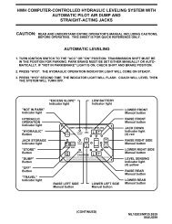
<strong>AIR</strong> <strong>SUSPENSIONS</strong> <strong>AND</strong> <strong>HWH</strong> ®1. PREFACEIn “Introduction to Air Suspensions” in our online technical school, the discussion was about what an airsuspension is, how it works and some of the basic components of the air suspension. If you have notreviewed that section yet, it would be helpful to do so before continuing with this discussion. If you areconfident you understand air suspensions, especially height control valves and pressure protection valves,please continue.This section will deal with how the <strong>HWH</strong> hydraulic leveling systems interface with the air suspension. Wewill discuss several types of suspension air dumps. We will also discuss how the <strong>HWH</strong> air levelingsystems interface with the air suspension to level the vehicle with the suspension air bags.2. HYDRAULIC LEVELING <strong>AND</strong> <strong>AIR</strong> <strong>SUSPENSIONS</strong>2-1 How air suspensions affect hydraulic leveling. Several factors combine to create issues when avehicle with an air suspension is being leveled with a hydraulic leveling system. The two main factors arethe compressibility of air and the transfer of weight through the suspension. As jacks lift a side or end ofthe vehicle, the suspension will usually shift weight to the other side or end of the vehicle. The addedweight compresses the air in the suspension air bags causing that side of the vehicle to lower. This bringsthe suspension height control valves into play. They start to raise the side that is being forced down withadded weight. This can defeat the action of the leveling jacks. In other words, the air suspension fightsthe leveling system. As the jacks are trying to turn out the leveling lights, the air suspension in moving theopposite side or end, causing the leveling lights to possible stay on longer than they should. The two sidesmost likely will seem to lift back and forth making the vehicle level at a much higher level than it should,if it can even achieve a level position. More than likely, this will create a bigger problem with side to sideleveling, because of the much shorter distance, than front to rear leveling.This problem is easily conquered. All you have to do is take the suspension air bags and height controlvalves out of the equation. This is done by exhausting all of the air from the suspension air bags anddisabling the height control valves. There is several ways to accomplish this. One way uses a normallyclosed set of valves supplied by <strong>HWH</strong> to dump the air from not only the air bags but also from the main airsupply. The other way uses a pilot valve arrangement supplied by the chassis manufacturer to exhaust airfrom the air bags and isolate the height control valves from the air bags. We will discuss each methodindividually.2-2 <strong>HWH</strong> air dump system. The <strong>HWH</strong> air dump system uses normally closed solenoid valves to dumpthe air from the vehicle suspension. The valves are teed into the air line that goes from the height controlvalves to the air bags. Usually there will be one air dump valve for each height control valve. Dependingon the suspension arrangement, sometimes it is possible to get by with two dump valves; one for the frontsuspension air bags and one for the rear suspension air bags. If installing a hydraulic leveling system ona vehicle with an air suspension, always contact <strong>HWH</strong> to obtain the proper air dump kit. The dumpvalves are controlled by the <strong>HWH</strong> leveling system controls. This type of system can be used with anautomatic leveling system or a manually controlled leveling system; either touch panel or lever controlled.Page 1 – 22JUL09
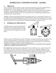
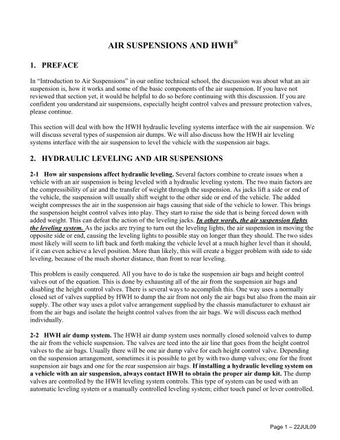
The following is a basic plumbing diagram for an <strong>HWH</strong> air dump system.Again, note that the <strong>HWH</strong> air dump valves are plumbed into the system between the height control valvesand the suspension air bags. Also note that on this drawing I have included the vehicle air supply alongwith the pressure protection valve. Remember, as the vehicle lowers, the height control valve linkageopens the valve to allow air to flow from the vehicle air supply into the air bags. This does happen as theair is dumped from the air bags and the vehicle lowers. When the <strong>HWH</strong> air dump valves are opened, theynot only dump air from the air bags but also (through the height control valves) from the vehicle airsupply. One of the important rules to follow when using an <strong>HWH</strong> air dump system is the vehicle enginemust be off. If the vehicle engine is allow to run while dumping air and leveling the vehicle, the vehicle airsupply will not dump properly. The vehicle engine air compressor will continue to fill the vehicle airsupply. When the <strong>HWH</strong> air dump valves are closed, air from the vehicle air supply will be allowed to flowto the air bags if a height control valve is still in a down position after the leveling process is complete. Ifthe system performs properly, at least one height control valve will probably be in the down position. Nowthe air bag for that height control valve will lift the vehicle back towards ride height. One or more jackswill not be on the ground. It will appear a jack has not extended properly or it retracted when it shouldn’t.2-2.1 Valve information. The <strong>HWH</strong> valve is a simple, normally closed, electrically operated solenoidvalve. The coil of the valve is a two wire potted coil that is reversible. That means the coil should be watertight and the polarity of the coil wires does not matter, as long as one wire is + voltage and the other wireis ground. The + voltage side of the coil will always be the switched (control) side. The ground should beconstant. The coil of the valve is a continuous duty coil and should open with 8 volts at the coil. The valveports are labeled “1” and “2”. We use port 2 for the inlet air pressure and port 1 is the outlet or dump side.Port 2 puts air pressure on the top side of the valve seat; this helps keep the valve closed.Page 2 – 22JUL09
2-2.2 Air dump operation. Except for the older 4 lever systems, the 400 series paddle switch systems and210/225 joystick systems, all <strong>HWH</strong> control panels will have a rocker switch or pushbutton for manual airdump control. The 210/225 systems have a harness that furnishes a wire for a rocker or toggle switch. Aharness for the air dump valve connections is also supplied. <strong>HWH</strong> supplies a momentary toggle switchwith a small air dump label. The installer can supply a different switch. It is recommended that this switchis a momentary switch with a continuous capability of 10 amps.For most systems, to use the manual air dump button, the ignition must be on, the park brake must be setand the control panel must be on. For the 625 single touch systems, the manual dump button will workwith only the ignition on and park brake set. For all systems, the manual dump button is a momentarybutton and will have to be held on while dumping the air. When the button is pushed, the + voltage isturned on. The valve coil is energized and the valve seat is opened. The air will now be dumped from theair suspension. When the button is released, the + voltage is turned off and the valve seat closes. The airwill stop dumping. With the air dump valves closed, the height control valves can cause the air bags toinflate, raising the vehicle back to ride height provided there is sufficient air pressure in the air supply.As stated earlier, the air must be dumped from the vehicle suspension before the leveling procedure isstarted. For manual systems and automatic systems being operated manually, the dump button must beheld until all air has exhausted from the air bags and suspension system. This means holding the dumpbutton until you do not hear any more air escaping from the valves. You can also use the air pressuregauges to see when no more air is escaping. When the air pressure gauges stop moving, that shouldindicate leveling can begin. Automatic systems will energize the air dump valves automatically before theleveling procedure is started. It is not necessary to manually dump the air. Systems with kick down stylejacks will start the air dump when the on (HYD) button is pushed a third time. Non-single step systemswill start the air dump when the on (HYD) button is pushed the second time. Single step systems will startdumping air as soon as the LEVEL button is pushed. Air will dump from the suspension for approximately20 seconds before the leveling process is started. The leveling process starts automatically after the 20second delay. The system will keep the air dump valves energized throughout the leveling process and turnthe valves off after the leveling process is completed and the system shuts off.It is important to understand the pressure protection valve on the vehicle air supply. This valvemaintains a specific amount of air pressure in the vehicle air supply for the vehicle air brake system in caseof a problem with the vehicle air suspension system or other non-brake related air equipment. This is whyafter no more air is exhausting from the suspension air dump valves the vehicle air system pressure gaugeswill still show 65 to 70 psi air pressure in the system. All RV related vehicles that I have encountered haveeither two pressure gauges or one gauge with two needles. Depending on how the vehicle air tanks areplumbed into the system, both gauges or needles will drop to the 70 psi range or possibly just one gauge orneedle will drop. In either case, when no more air is exhausting from the air dump valves, there shouldbe approximately 65 or 70 psi remaining in the vehicle air system. This can create a problem for theleveling system. The pressure protection valves are not required to be a “zero” leak valve. This may allowair to leak by the protection valve to the vehicle suspension. Over a period of time, depending on the sizeof the leak, height control valves in the down position will allow this air to flow to its air bag. This can liftthe vehicle, raising one or more jacks off the ground. This can make it appear these jacks are retracting bythemselves.Page 3 – 22JUL09
To check this, simply turn the leveling system controls on and push the manual “DUMP” button. If airstarts to exhaust from the air dump valves, and the vehicle lowers, the protection valve is leaking. Theproblem is that because the protection valve is not a zero leak valve, there is no real repair for this unlessthe leak exceeds the allowable DOT tests. Even putting a new protection valve in the system will notguarantee a solution for the problem. Pumping the brake pedal to lower the air pressure in the vehicle airsupply to approximately 30 psi is the only real solution. As long as there is not enough air pressure toactually raise the vehicle, a leaky protection valve will not affect the system.Returning a vehicle to ride height is very simple; start the engine and build up some air pressure. The airdump valves should be closed unless the system is in an automatic leveling mode or the control panel is onand the dump button is being pushed. As the vehicle lowers when the jacks are retracted, the height controlvalves will be in the raise position. Air will be directed to the air bags until the vehicle is at the correct rideheight.WARNING: DO NOT CRAWL UNDER A VEHICLE UNLESS THE FRAME OF THE VEHICLEIS PROPERLY SUPPORTED. DO NOT USE THE <strong>AIR</strong> SUSPENSION OR LEVELING JACKSTO SUPPORT THE VEHICLE WHILE UNDER THE VEHICLE.2-2.3 <strong>HWH</strong> air dump valve diagnostics. The diagnostics for the air dump valves is also very simple.If the valves will not dump air, first determine if one or all valves will not dump air. If no valves willdump air, the control box or panel would probably be the best place to start. If any one valve is working,that indicates the control box or panel is working. (The 4 lever 100/110 systems have two separate outputsfor the front and rear valves. Although unlikely, if front or rear valves are working and the others are not,it could be the control panel.) In either case, starting at the dump valves should always get you to theproblem. First, check the exhaust ports of the valves for blockage; these ports can become clogged withdirt or small bug homes. If the ports are not plugged, check for voltage between the two wires for thevalve. You need at least 9 volts (with the valve plugged in and turned on) to open a dump valve. If goodvoltage is present, the dump valve is bad. If voltage is not present, work your way back to the control boxor panel to determine where the problem lies.If the vehicle will not return to ride height, check to see if air is exhausting from the dump valves. If noair is exhausting from the dump valves, the problem is with the vehicle suspension, probably the heightcontrol valves. If air is exhausting from a dump valve, unplug the valve. If the valve continues to exhaustair, the valve is the problem. If the valve closes when unplugged, the harness wires are shorted to + voltageor the controls are bad.2-3 Pilot air dump systems. The valves and other equipment for a pilot air dump system are provided bythe vehicle or chassis manufacturer. This type of system can be controlled mechanically or electrically.Electric controls can be provided by the vehicle manufacturer or can be part of the <strong>HWH</strong> leveling system.The diagram on the following page represents a typical pilot air dump system. It is important tounderstand that this equipment IS NOT supplied by <strong>HWH</strong>. This equipment is supplied and installed bythe vehicle or chassis manufacturer. It is important for you to contact the manufacturer beforediagnosing or attempting to repair a pilot air dump system. For a detailed review and explanation of thepilot air dump equipment, refer to the vehicle or chassis manufacturer.Page 4 – 22JUL09
TYPICAL PILOT <strong>AIR</strong> DUMP SYSTEMPilot DumpValve Exhaust ªFigure 3An advantage of using a pilot dump system is that the dump valve isolates the air bag from the heightcontrol valve while dumping the air from the air bags. Air is not dumped from the main air supply and thevehicle engine can be run during a leveling procedure. Another advantage is the pilot dump valve stays inthe position it is shifted to. This means there should be no problem with air seeping into the air bags afterthe leveling procedure is finished. BUT, this can also be a disadvantage if there is a system failure. If afailure causes the pilot valve to not shift into the travel position, the vehicle cannot return to ride height.2-3.1 Pilot air dump equipment. The pilot air dump system consists of a pilot control valve and a dumpvalve at each height control valve along with the necessary plumbing and wiring. The electrically operatedpilot control valve has an electric coil on each side of the valve. Switched + voltage is used to energizethese coils. When a coil is energized, the pilot valve is shifted to the travel or dump position. In the travelposition, the pilot control valve connects the individual dump valves to an exhaust port. This allows thedump valves to shift to the travel position, allowing the height control valves to control the air in the airbags. In the dump position, the pilot control valves uses air pressure to shift the individual dump valves tothe dump position. In the dump position, the height control valves are isolated from the air bags and the airis exhausted from the air bags.Note: Air pressure is required to shift the pilot control valve from one position to another. If the system airpressure is low, the valve may not shift until adequate air pressure is built up in the system with the engineair compressor.Page 5 – 22JUL09
The following diagrams represent the two different positions of the pilot dump valve, travel and dump.2-3.2 <strong>HWH</strong> pilot dump controls are part of the system control box or control panel. There will be a +voltage output for dump and travel. With a touch panel controlled system, each output will be fused. Witha 200 series joystick leveling system, both outputs are protected with the main panel fuse. <strong>HWH</strong> supplies aharness to connect to the pilot control valve. This harness has three wires in it and terminates into a 4 pinUML connector. The three wires are a black wire labeled 9300 for the dump signal, a black wire labeled9301 for the travel signal and a white wire for ground. One end pin has no wire, the next wire is the whiteground wire, the next wire is the black 9301 travel wire and the other end pin is the black 9300 dump wire.Refer to system electrical connection diagrams for specific control box or panel connections, fuselocations and led information where applicable.2-3.3 Pilot dump operation. Each different type of control system operates the pilot dump system a littledifferently. One thing that is consistent between all of the systems is that the ignition must be on and thepark brake must be set for the pilot dump system to dump the air. Another consistent feature is when theignition is on and the park brake is off, there is a + voltage signal to the travel side of the pilot controlvalve.There are several types of pilot dump controls for past or present, manual and automatic systems.1.) There is a rocker switch panel that can be used with or without any leveling system. The panel onlyhas a fuse and a rocker switch. With the ignition on and the park brake set, push the rocker to “<strong>AIR</strong>DUMP”. This will shift the pilot control valve to the dump position and the air will dump from the airbags. With the ignition on, push the rocker switch to “TRAVEL”. This will shift the pilot control valve tothe travel position. The air bags should start to fill and the vehicle should return to ride height. If theignition is on and the park brake is released, the pilot control valve will shift to the travel position.Page 6 – 22JUL09
7.) 625 automatic leveling system. The touch panel has a “DUMP” button and is the same panel for eitherthe pilot dump system or the <strong>HWH</strong> dump valve system. The ignition must be on (or in accessory), the parkbrake must be set and the touch panel must be on for the “DUMP” button to work. When the “DUMP”button is pushed, the control box turns the travel relay and the dump relay on. The travel relay is anormally closed relay so when the dump button is pushed, the travel relay contacts open and the dumprelay contacts close. This supplies a + voltage signal to the pilot control valve to shift the valve to thedump position. The signal is constant until the “OFF” button is pushed or the ignition is turned off. Forautomatic leveling, when the “ON” (HYD) button is pushed to start the actual leveling process, the travelrelay and the dump relay is turned on. This supplies a + voltage signal to the pilot control valve to shift itinto the dump position. The dump signal is constant until the touch panel turns off or the ignition is turnedoff. After the “DUMP” button has been pushed or the automatic leveling function is used, any time theignition is turned on, the control box will pulse the dump relay on to make sure the pilot control valvestays in the dump position. To return the pilot control valve to the travel position, the ignition must be on.If the park brake is on, pushing the “STORE” button will turn off the travel relay. When the travel relay isoff, the normally closed contacts of the travel relay direct + voltage to the pilot control valve. The pilotvalve shifts to the travel position. The travel signal is then constant any time the ignition is on. If theignition is on and the park brake is released, the travel relay is turned off and a constant + voltage signal isdirected to the pilot control valve.8.) 625S single step automatic leveling system. The touch panel has a “DUMP” button and is the samepanel for either the pilot dump system or the <strong>HWH</strong> dump valve system. The ignition must be on (or inaccessory) and the park brake must be set for the “DUMP” button to work. When the “DUMP” button ispushed, the control box turns the travel relay and the dump relay on. The travel relay is a normally closedrelay so when the dump button is pushed, the travel relay contacts open and the dump relay contacts close.This supplies a + voltage signal to the pilot control valve to shift the valve to the dump position. The signalis constant until the “EMERGENCY STOP/CANCEL” button is pushed or the ignition is turned off. Forautomatic leveling, when the “LEVEL” button is pushed to start the actual leveling process, the travelrelay and the dump relay is turned on. This supplies a + voltage signal to the pilot control valve to shift itinto the dump position. The dump signal is constant until the leveling and stabilizing process is completeor the ignition is turned off. After the “DUMP” button has been pushed or the automatic leveling functionis used, any time the ignition is turned on, the control box will pulse the dump relay on to make sure thepilot control valve stays in the dump position. To return the pilot control valve to the travel position, theignition must be on. If the park brake is on, pushing the “STORE” button will turn off the travel relay.When the travel relay is off, the normally closed contacts of the travel relay direct + voltage to the pilotcontrol valve. The pilot valve shifts to the travel position. The travel signal is then constant any time theignition is on. If the ignition is on and the park brake is released, the travel relay is turned off and aconstant + voltage signal is directed to the pilot control valve.2-3.4 PILOT DUMP DIAGNOSTICS. For <strong>HWH</strong>, pilot dump diagnostics consists of testing for a +voltage signal to shift the pilot control valve to the dump or travel position. All <strong>HWH</strong> systems that controlthe pilot dump have a straight 4-pin UML connector with three wires that connect to a harness supplied bythe vehicle manufacturer. There are two black wires (9300 – Dump & 9301 – Travel) and one white wirefor ground. The hardest part of diagnosing a pilot dump issue will be determining which <strong>HWH</strong> system isbeing used and where to locate the 4-pin plug. Contact <strong>HWH</strong> <strong>Corporation</strong> for assistance with either issue.Refer to the above information to determine when there will be a signal for dump and travel.Page 9 – 22JUL09
Check the appropriate fuse. If the fuse is ok, then check for + voltage between the appropriate black wire(9300 – Dump & 9301 – Travel) and the white ground wire. If voltage is present, the issue is with the pilotdump equipment and you should contact the vehicle or chassis manufacturer. If voltage is not present,check for voltage on the correct output pin. If voltage is present, there is a problem with the harness wiresor connections. If voltage is not present, the problem is most likely the control box or panel. If the fuse isblown, unplug the 4-pin UML connector and replace the fuse. If the fuse now blows, there is a short in theharness or control box/panel. If the fuse does not blow with the harness unplugged, the problem is with thevehicle pilot dump wiring or equipment. Contact the vehicle or chassis manufacturer.3. <strong>HWH</strong> <strong>AIR</strong> LEVELINGThis discussion will cover the basic <strong>HWH</strong> air leveling systems. This section will not cover the <strong>HWH</strong>Active Air system. The Active Air system will be discussed as an individual subject in the <strong>HWH</strong> onlinetechnical school.3-1 What is air leveling? Very simply, air leveling uses the vehicle’s air suspension to level the vehicle.<strong>HWH</strong> isolates the suspension air bags from the heights control valves. This way <strong>HWH</strong> can control the airbags for leveling. To level the vehicle, air is released from the suspension air bags to lower the vehicle oradded to the suspension air bags to raise the vehicle. This is done using the <strong>HWH</strong> Bi-Axis ® levelingprinciple.Bi-Axis ® leveling. Bi-Axis is working with two corners of the vehicle at a time to level the vehicle side toside and then front to rear. If the left side is low, the right rear and right front corners are raised to level thevehicle side to side. If the front is low, both front corners of the vehicle are raised to level the vehicle.With a motorized vehicle, you always level the vehicle (if needed) side to side before leveling front to rear.All present day air leveling systems incorporate the Bi-Axis four point leveling principle, but the original500 series air leveling system and some early 600 series air leveling systems were three point levelingsystems. That means the two rear corners were controlled independently but the two front corners werecontrolled together. With a four point system, there is a raise, lower and travel valve for each corner of thevehicle. With a three point system, there is only one raise, lower and travel valve for both front corners.This will be explained in greater detail later in the <strong>HWH</strong> Air Leveling section of this lesson.The majority of air leveling systems are installed by the vehicle manufacturer but air leveling can beinstalled on any vehicle with a full air suspension that incorporates height control valves. This is not anormal aftermarket installation but an air leveling system can be installed on an existing vehicle with theapproval of <strong>HWH</strong> <strong>Corporation</strong>. The installer must be approved by <strong>HWH</strong> <strong>Corporation</strong>.Air leveling systems can also be combined with the <strong>HWH</strong> hydraulic leveling systems. This system usesone control box and touch panel. Vehicles equipped with a combination air or hydraulic system gives theoperator the choice of using either the air leveling system or the hydraulic leveling system. If one systemhas been used to level the vehicle, do not use the other system. Example: If the hydraulic system wasused to level the vehicle, do not use the air leveling system unless the hydraulic system has been retracted.Page 10 – 22JUL09
3-2 Components of a basic air leveling system. (This does not include the <strong>HWH</strong> Active Air system)The main components of an air leveling system are the control box, touch panel, air solenoid valvemanifolds and an auxiliary air compressor. The older systems have a remote mounted level sensing unit.There is also the wiring harnesses which are normally supplied by <strong>HWH</strong> although a few manufacturersmay supply some of the harnesses. Plumbing equipment such as air lines or fittings other than thosesupplied with the <strong>HWH</strong> air manifolds and air compressors are supplied by the installer.3-2.1 Control boxes. The control box processes information received from the touch panel, level sensingunit and pressure switches to control system indicator lights and the leveling equipment. Although a fewmanual control air leveling systems were produced in the mid 1990s, most of those were upgraded toautomatic leveling system and all present day air leveling systems are computerized, automatic levelingsystems. All control boxes will have a computer chip with a 4 or 5 digit number on it. The number mayalso have a – number. Example: A9636-5 The A may not be present. The number and the – number arewhat is needed to identify a program. You may be asked to provide this number if specific programminginformation is needed when diagnosing air leveling issues.There have been several different style control boxes for air leveling. The original air leveling system wasthe 500 series system. This system used a 9” X 14” aluminum control box. The next generation was the600 series system. This control box looked exactly like the 500 series. The difference between the twosystems was the touch panel cable. The 500 series system used a 2” wide flat ribbon touch panel cable.The 600 series system used a ½” wide modular touch panel cable. Both systems remained in use untilabout 2002. The 500 series control box is still used for Prevost buses that use <strong>HWH</strong> air leveling.The 680 series system was a bridge system to the 2000 series CAN system that is in use today. The 680series control box was 14” x 18” aluminum box. Instead of plugs in the box, most of the connections to thebox were made to connectors on short pigtails coming from the box. This box was only used if the vehiclehad <strong>HWH</strong> room mechanisms with <strong>HWH</strong> room locks and air seals. The air leveling side of this type ofcontrol box was like the 600 series leveling system. In fact the same two computer pc boards used in the600 box are used in the 680 box. The program number used is different and the output boards use relaysinstead of transistors. A modular touch panel cable is used.Page 11 – 22JUL09
The 2000 series CAN system is the system that is presently used for all air leveling systems except thoseused for Prevost busses. The Active Air system is a CAN system with a different type of system control.CAN stands for Controller Area Network. The CAN system has a central control module with a “mother”board along with input and output modules that the central control module controls. A simple CAN systemwill only have only two modules or boxes; a central control/output box and a touch panel. In a CANsystem, the touch panel is considered a module. A complex CAN system can have an almost unlimitedamount of control boxes or modules. Except for one or two possible exceptions, all air leveling only CANsystems will have only the two modules; the control box and the touch panel.3-2.2 Touch panels. There are several different styles of touch panels for air leveling systems. It isimportant to get the correct part number when replacing a touch panel. A replacement panel with the samelexan (touch panel decal) and cable connector may not be compatible with the existing panel. Some touchpanels may have a small sticker on the back with the panel part number. Some will have the part numberwritten on the pc board with a felt pen. If no part number is available, get the part number off the controlbox. With the control box number, the correct touch panel part number can be determined by <strong>HWH</strong>. Thefollowing panels are examples of what is available. When part numbers are not available, contact <strong>HWH</strong><strong>Corporation</strong> technical assistance. Do not order a touch panel unless you are positive of the correct partnumber.Page 12 – 22JUL09
The basic air manifold has a left side and a right side. Each side has three valves that do the same thing.1.) The travel valve is used to isolate the air bags from the height control valves. When traveling, thisvalve is open to allow the height control valves to function. When leveling, the travel valves are closed,this isolates the air bags from the height control valves.2.) The raise valve is used to direct air into the air bags. This raises the vehicle.3.) The lower valve is used to exhaust air from the air bags. This lowers the vehicle.The drawing below is an air manifold for the drive axle of a vehicle. It is labeled as a present daymanifold. Either side of the manifold can be right or left but <strong>HWH</strong> now labels left and right on themanifolds. It is important to pay attention to the labeling because the valves are prewired with a shortpigtail. The right and left side air lines must be plumbed into the right and left side valves. On oldermanifolds that are not labeled, you must maintain the proper wiring and plumbing connections.3-2.3.1 The air solenoid valves are normally closed valves operated with a + 12 volt, continuous dutycoil. The + voltage to the valve coil is always the switched (control) side of the coil. The valve is requiredto open with 8 volts. If there is less than 8 volts, the valve may not function. The valve is a screw on valvewith two o-rings, an inner o-ring and an outer o-ring. The o-rings should be lightly lubricated before thevalve is installed.Valve diagnostics. Check the voltage between the two wires for the coil. The valve needs to be plugged inand turned on. If there is at least 8 volts to the coil, the valve should open, allow air to flow. If the valvewill open it is ok. If the valve will not open, replacing the coil will probably fix the valve. If the coil of thevalve is bad, the coil itself can be replaced. If replacing the coil, the u-shaped steel bracket must beretained. If there is less than 8 volts or 0 volts to the coil, the diagnostics must move to the system controlsor harness.Page 14 – 22JUL09
3-2.3.2 Air pressure switches. Pressure switches are used to monitor air bag pressure or system pressure.The first air leveling systems will have no manifold pressure switches. Air pressure switches were notincorporated into the systems until the early to mid 1990’s. The first air leveling systems with pressureswitches will have 4 air bag pressure switches, one for each corner of the suspension, with no systempressure switch. These pressure switches were only used as low air bag pressure warning switches. As theair leveling systems evolved, a system pressure switch was added and the air bag switches were also usedduring the leveling procedure. There have been different styles and pressure ratings for these switches.The different air pressure switches are discussed in detail in Lesson 9 “Electronics and <strong>HWH</strong>” in theon line technical school. The most common air bag switch is a 20 psi switch. 10 psi and 35 psi switcheshave been used. The most common system pressure switch is an 85 psi switch. A 100 psi system pressureswitch has been used. The pressure switch rating is commonly included in the part number that is on theswitch itself and is also included on the part number tag added by <strong>HWH</strong>.The air manifold pressure switches havenormally closed contacts and open whenthe pressure switch rating is reached.Example: From 0 to 20 psi, the contacts ofa 20 psi air bag switch are closed. Whenthe pressure in the air bag reaches 20 psi,the switch contacts open. The air manifoldpressure switches switch a ground signal toprovide information to the control box.The system pressure switch is used as alow air pressure warning switch only. Itmonitors the air pressure that is in thesuspension system after the pressureprotection valve.The air bag pressure switches are used as air bag low air pressure warning switches when the system is inthe travel mode. When the system is in the leveling mode, the air bag pressure switches are used to protectthe vehicle from excessive twisting during the leveling procedure, specifically when the system is doing alower procedure. The program for this has changed several times and a specific chip number may beneeded to describe the program used by the existing control box. The air bag pressure switch program thatis in use at the time this is being written is as follows:Automatic leveling-pressure switch program. When the system is performing a front (or rear) lowerprocedure and either front (or rear) pressure switch comes on, low air pressure in an air bag, the lowerprocedure will halt. The system will immediately go into a raise procedure for the opposite end to try toachieve a level position. The system will not return to a lower procedure during the present levelingsequence. The system will use a lower procedure if re-leveling the vehicle in the sleep mode. The systemstill monitors the air bag pressure switches and will inhibit a front or rear lowering procedure if an air bagpressure switch comes on.Manual leveling-pressure switch program. If either front air bag pressure switch is on, the systemcannot perform a front lower procedure, the front down arrow (lower) button will not function. Both sidedown arrow buttons will still function and the rear down arrow button will function. Any up arrow (raise)button will function.Page 15 – 22JUL09
If either rear air bag pressure switch is on, the system cannot perform a rear lower function. The rear downarrow (lower) button will not function. Both side down arrow buttons will still function and the front downarrow button will function. Any up arrow (raise) button will function.The all “DUMP” and “RAISE” buttons will function with any air bag pressure switch on. The air bagpressure switches do not inhibit the “DUMP” or “RAISE” buttons.WARNING: DO NOT CRAWL UNDER A VEHICLE UNLESS THE FRAME OF THE VEHICLEIS PROPERLY SUPPORTED. DO NOT USE THE <strong>AIR</strong> SUSPENSION OR LEVELING JACKSTO SUPPORT THE VEHICLE WHILE UNDER THE VEHICLE.Pressure switch diagnostics. The air manifold pressure switches are normally closed switches that switcha ground signal. With low system or air bag air pressure, there should be continuity between the two wiresof the switch. Use the vehicle brake pedal to lower the system air pressure to check the system air pressureswitch. Get the vehicle air gauges to 70 psi or lower, the system air pressure switch contacts should beclosed. Start the engine to build air pressure. As the vehicle pressure gauges reach the rating of the pressureswitch, the switch contacts should open. Use the “DUMP” button or down arrows to empty suspension airbags. When the bags are empty, the air bag pressure switch contacts should be closed. Use up arrows toadd air to the air bags. You would have to put an inline pressure gauge between the air bags and <strong>HWH</strong>manifold to get a precise reading of when the switch contacts open, but in general, the pressure switchcontacts should open a few seconds after an up arrow is pushed. Remember, the air bag pressure switchcontacts will open at a fairly low pressure, 10 to 35 psi.3-2.3.3 Air manifold air line fittings. <strong>HWH</strong> uses two types of air line fittings, the compression stylefitting and the “push-in” fitting. Any fittings used for air line connections in the air suspension must beDOT approved. The fitting must have a “DOT” stamp on it. The DOT stamp may not always be in themost visible place. The DOT stamp is on the face of the lock ring of the push-in fittings.Compression fittings. Compression fittings have three main components; the main body, the compressionsleeve and the nut. The main body also has a tube support sleeve. The support sleeve prevents the air linefrom collapsing and allows the compression sleeve make a proper seal with the air line. If an existing airline is removed, it can be reused without replacing the compression sleeve which would require cutting offthe end of the air line. If the support sleeve is removed with the air line and the line must be cut, a newsupport sleeve must be used. Nuts and compression sleeves can be replaced without replacing the mainfitting body. When tightening a new compression sleeve, the nut must be tightened enough to slightlycrush the compression sleeve and create a leak free air seal. Refer to Parker Hannifin <strong>Corporation</strong> fordetailed tightening or re-tightening instructions.Page 16 – 22JUL09
Push-in fittings. Push-in fittings make installation and removal of air lines easier. There is no tighteningprocedure to secure and seal the air line. The push-in fittings are reusable. To install an air line, make surethe end of the line has a good square cut. When cutting the line, it is best to use a good scissor type tubecutter to prevent the line from being crushed while cutting. Push the line into the fitting until it bottomsout. Pull back on the line to make sure it is locked in place. To remove the line, push the locking ringtoward the main body of the fitting then pull the line from the fitting. It will be easier to remove the air lineif the air pressure is removed from the circuit. When removed, the end of the line will show some gripmarks. It is best to cut off enough line to remove these grip marks. If the grip marks are not removed, theconnection may leak.3-2.3.4 Air manifold check valves. Standard air manifolds have a right and left check valve. The checkvalves perform two functions. They prevent air from flowing from the high pressure air bag to the lowpressure air bag when both raise valves on the manifold are opened. They also prevent air from flowingfrom the air bag back to the air supply when a raise valve is opened. To date, I know of no air manifoldcheck valve ever being replaced.3-2.3.5 Travel by-pass T-handle. The by-pass T-handle is not on all air manifolds. The T-handle wasadded as an aid to the vehicle manufacturers. When open, air from the height control valve by-passes thetravel valve and is directed to the air bag. This allows the vehicle manufacturer to use shop air to keep thevehicle at ride height during the manufacturing process without having to energize the travel solenoidvalves. The only real problem the T-handle has caused is the manufacturer will sometimes forget to closethe T-handle when production of the vehicle is complete. If a T-handle is open, any time the vehicle israised, lowered or leveled, any corner with an open T-handle will return to ride height, depending onavailable air supply. The by-pass T-handles should not be used as an emergency by-pass by thevehicle operator. Most air manifolds are mounted under the vehicle in areas with limited access. Turningthe T-handle will cause the vehicle to move up or down which will be a hazard to anyone under thevehicle.WARNING: DO NOT CRAWL UNDER A VEHICLE UNLESS THE FRAME OF THE VEHICLEIS PROPERLY SUPPORTED. DO NOT USE THE <strong>AIR</strong> SUSPENSION OR LEVELING JACKSTO SUPPORT THE VEHICLE WHILE UNDER THE VEHICLE.Page 17 – 22JUL09
3-2.4 The auxiliary air compressor. Air leveling systems have a program called the “sleep mode”. Thesleep mode monitors the levelness of the vehicle and if needed, the system will “wake up” and re-level thevehicle. Because this happens when the vehicle engine is not running, it is possible the vehicle air supplywill not be adequate to re-level the vehicle. This is the primary job of the auxiliary air compressor, tosupply air to the leveling system air manifolds for re-leveling the vehicle when in the sleep mode. Theauxiliary air compressor is also used on some vehicles to maintain an auxiliary air tank to supply air tovehicle air equipment such as room air seals or toilets. Some manufacturers even allow the auxiliary aircompressor to maintain a minimum air pressure in the vehicle’s main air tanks. Of course this means thereare different size air compressors and many different compressor/valve/output arrangements.<strong>HWH</strong> uses two basic 12 volt compressors. They are both Thomas compressors. One has a larger air flowcapability than the other. The smaller compressor develops .43 cfm at 60 psi and .27 cfm at 100 psi. Thepressure relief for the smaller compressor is normally set at about 110 to 115 psi. The larger compressordevelops .95 cfm at 100 psi and .70 cfm at 140 psi. The relief for the larger compressor may be set as highas 140 psi.When dealing with air compressor issues it may be best to contact <strong>HWH</strong> for specific system or componentdrawings or diagrams. Single output compressors are fairly simple. The compressor is supplied powerthrough a relay controlled by a + 12 volt signal from the <strong>HWH</strong> control box. Normally that signal goesthrough a pressure switch so the compressor will only run if the air pressure available from the vehicle airsupply is low. The relay and pressure switch are part of the compressor assembly. A few systems run the<strong>HWH</strong> control signal directly to the compressor control relay so the compressor runs any time the <strong>HWH</strong>system calls for the compressor. Multiple output compressors will be more complex with differentwiring, pressure switch and valve arrangements. One output may be controlled by a valve; another may becontrolled by a pressure switch. The control signal for air leveling will always come from the <strong>HWH</strong>control box. The control signal for other outputs will come from vehicle controls. Possibly, an auxiliaryoutput may be controlled by a pressure switch that switches battery power. That way any time there is lowair pressure on that particular circuit, the compressor will run. There may be a dash switch to control theair compressor. As you can see, with the many variations available, especially with multiple outputcompressors, it is important to get the correct drawings and diagrams for diagnostic help.The small compressor requires a 10 amp fuse and the large compressor requires a 30 amp fuse. Neithercompressor is a sealed unit so they must be protected from dirt and moisture such as caused by road sprayfrom tires.Page 18 – 22JUL09
3-2.5 Specialty air manifolds. There are many variations of air leveling manifolds but there are two thatare different than the basic manifolds and also very common. Both manifolds are tag axle manifolds.One is an eight valve tag lift manifold used to control the tag lift mechanism. Six of the valves are thenormal travel, lower and raise valves. One of the remaining valves is the tag lift valve and supplies air tothe tag lift mechanism to lift the tag axle. The other remaining valve is the tag lift exhaust valve. Thisvalve exhausts air from the tag lift air bags to lower the tag axle. The lower valves, the tag lift valve andthe tag lift exhaust valve are different than the standard air manifold valves. They are the large orificevalves. When traveling or performing a leveling procedure, the 6 main tag axle valves work in unison withthe drive axle valves. The tag lift exhaust valve is on anytime the tag axle travel valves are on. Whenexecuting a tag lift procedure, the tag axle travel valves are turned off, the tag axle dump valves are turnedon and the tag lift valve is turned on. This exhausts air from the tag axle air bags and lifts the tag axle.The other manifold is a six valve tag lift manifold. This manifold has two tag enable valves (a right and aleft), two exhaust valves (a right and a left), a tag lift valve and a tag lift exhaust valve. The tag enablevalves connect the tag axle air bags to the drive axle air bags. These valves are on (open) any time thesystem is in the travel mode, a leveling mode (manual or automatic) and when performing an all raise orall lower function. The tag enable valves are turned off if a tag lift function is performed. When a tag liftfunction is performed, the tag enable valves are turned off, the tag exhaust valves are turned on (thisempties the tag axle air bags) and the tag lift valve is turned on. This supplies air to the tag lift assembly tolift the tag axle. When in the travel mode or any time the tag enable valves are on, the tag lift exhaust valveis on. This exhausts air from the tag lift mechanism to lower the tag axle back to the ground. The valvesused on this manifold are the same as the valves used on the standard air manifolds except the two exhaustvalves. They are a different part number and have a larger orifice to exhaust the air quicker.Page 19 – 22JUL09
3-3 System plumbing. Although there will be slight variations in plumbing between differentmanufacturers and vehicles, the basic plumbing of the <strong>HWH</strong> equipment is fairly consistent. One variationdepends on the number of air bags on each side of an axle. Some suspensions use one bag per side; someuse two bags per side. When two bags are used, they are plumbed together. Some manufacturers tee thebags together after the <strong>HWH</strong> air manifold and some plumb in one line per bag to the manifold. Thefollowing diagrams show several ways the <strong>HWH</strong> equipment may be plumbed into the suspension. Animportant thing to note is the position of check valves for the air compressor. It is important that the airlines between the auxiliary air compressor and the <strong>HWH</strong> leveling manifold air supply are checked so theair compressor is not trying to feed the vehicle air supply while leveling the vehicle. When not checkedproperly, the auxiliary air compressor may not be able to supply enough air to level the vehicle whiletrying to fill the suspension or auxiliary air tanks.Figure 26 is a standard air leveling system with oneair bag per corner with no tag axleFigure 27 is an air leveling system with two air bagsper corner with a tag axle. The tag has one air bag perside and is controlled by the drive axle height controlvalves. The front and drive axle bags are plumbedindependently to the leveling manifolds.Figure 28 is an air leveling system with two air bagsper side on the drive axle only. The bags tee togetherbefore the leveling manifold. The drive axle heightcontrol valves control the tag axle and the system hasa tag lift controlled by the <strong>HWH</strong> tag axle manifold.Page 20 – 22JUL09
The following diagrams show detailed connections for several styles of manifolds.Figure 29 is a front air manifold with two 20 psi air bagpressure switches and a single air bag connection foreach side.Figure 30 is a drive axle manifold. It has two 20 psi airbag pressure switches and an 85 psi system pressureswitch. This manifold has connections for two air bagson each side.Figure 31 is a tag axle manifold. It has two 20 psi airbag pressure switches. This manifold has no heightcontrol valve connections but is connected to the left andright side drive axle air bags. The drive axle heightcontrol valves control the tag axle air bags. There is asingle air bag connection on each side and a connectionfor the tag lift mechanism.3-4 System wiring. The system wiring, like the plumbing can vary between manufacturers and vehicles.With the older 500 and 600 series leveling systems, the wiring was very consistent and only changed if atag axle lift was incorporated into the system. Even vehicles with a tag axle were not complicated. Whentraveling or leveling, the tag and drive axles were controlled as one axle. If a tag lift was used, relays in thecontrol box isolated the tag from the drive axle so the tag axle air bags could be dumped and the tag lifted.The basic, single control box 2000 series CAN air leveling system is wired much like a 500 or 600 seriessystem. The two main differences are the CAN system has the ability to recognize a signal from thetransmission speed switch for the “Dump” and “Raise” functions and the CAN control box uses four powerinputs instead of the three that the 500 and 600 systems used. Electrical information for specific systemswill be discussed in greater detail in Lesson 14 of the <strong>HWH</strong> Online Technical school.It is important to get specific wiring diagrams and/or system schematics when addressing wiringissues. Repair manuals are available for the 500 series, 600 series and the single control box 2000series CAN leveling systems. These manuals contain basic wiring diagrams for these systems.Page 21 – 22JUL09
3-5 The five basic “modes” of the air leveling system; travel mode, raise or dump mode, levelingmode, sleep mode and excess slope mode. Touch panel lights and buttons are shown in Figure 32.3-5.1 Travel Mode. The travel mode is when the suspension height control valves, through the <strong>HWH</strong>travel valves, control the vehicle ride height. The vehicle ignition must be on for the system to be in thetravel mode. In the travel mode, the <strong>HWH</strong> air manifold travel solenoid valves will be on. For vehicles witha tag lift manifold, the tag enable valves will be on in the travel mode. This allows the suspension heightcontrol valves to control the suspension air bags and keep the vehicle at ride height. The system touchpanel has either a “TRAVEL” or “TRAVEL MODE” indicator light that will be on when the system is inthe travel mode and the ignition is on. If an air bag or the system has low air pressure the travel/travelmode light will go out and a dash warning light will come on. Even though the travel/travel mode lightis off when air pressure is low, the air manifold travel valves will still be on (open). If the vehicle has atag axle with a tag lift, the travel/travel mode light will not be on if the tag lift is on. When a tag liftfunction is performed, the front and rear travel valves remain on so the height control valves can maintainproper vehicle ride height. With early systems, the system will be in the travel mode anytime the ignition ison and the <strong>HWH</strong> touch panel is off. Later systems have a “TRAVEL MODE” button that must be pushedto return the system to the travel mode, even if the touch panel has been turned off. With any air levelingsystem, the system will be in the travel mode anytime the ignition is on and the park brake is released;except when the “RAISE” or “DUMP” buttons are being used.3-5.2 Raise or Dump mode. Most system touch panels have a “RAISE” and a “DUMP” button. A few airleveling panels will not have the “RAISE” button. The raise and dump buttons are used to raise or lower allfour corners of the vehicle at the same time. The system is designed to allow the use of the raise and dumpbuttons while the vehicle is moving, such as getting over a curb or under a tree limb. It is important thatthe vehicle is moved at very slow speeds for short distances when the raise or dump button is used.Page 22 – 22JUL09
The “RAISE” or “DUMP” buttons will function with the system on or off but not while in an automaticleveling mode. The park brake does not need to be set to use the raise or dump button. With most 500 and600 series control boxes, the buttons are momentary and will only dump or raise while the buttons arepushed. After a two second delay, the suspension returns to ride height when the raise or dump button isreleased if the ignition is on. The 2000 series CAN system will latch the raise or dump feature in if thetransmission speed switch is connected to the <strong>HWH</strong> control box. This means the vehicle can be movedwithout holding the dump or raise button. It is important to understand that if the system has the latchin feature, the vehicle will lower or raise to its maximum capability when the dump or raise button ispushed. The system will unlatch and return to ride height when a pre-programmed speed, usually 15 mphor less, is reached. With any system, the touch panel will turn off after the raise or dump button is used.The raise and dump features are supplied with most <strong>HWH</strong> air leveling systems. This section and<strong>HWH</strong> operator’s manuals explain how to use the “RAISE” and “DUMP” buttons and how thesystem will react when using the buttons. The appropriate use of these features is determined by thevehicle manufacturer.3-5.3 Leveling modes. The leveling mode has two options; manual control or automatic control. For eithermethod of leveling, the touch panel must be turned on by pushing the “<strong>AIR</strong>” button one time. With earlysystems, the panel could be turned on with the ignition on or off. If the ignition was on, the park brake hadto be set. It the ignition was off, the park brake did not have to be set. With later and the present daysystems, the ignition must be on and the park brake must be set to turn the touch panel on. Once the panelis on, the ignition can be turned off. When initially leveling the vehicle, manually or automatically, it isbest to have the vehicle engine running. This creates a better air supply when leveling the vehicle with araise function. The touch panel has four yellow level indicator lights; a front light, a rear light, a left sidelight and a right side light. These lights will work when the touch panel is on. A lit yellow level lightmeans a side or end of the vehicle is low. When all four level indicator lights are off, the vehicle is level. Alit level light also means the opposite side or end is high. It is possible to attempt to level the vehicle bylowering the high side or end.3-5.3.1 Manual leveling. When the touch panel is on, the up and down arrows on the right hand side of thetouch panel can be used to manually level the vehicle. The up arrows open the raise valves and lift thevehicle. The down arrows open the lower valves and lower the vehicle. Each button raises (up arrows) orlowers (down arrows) two corners of the vehicle at the same time. If the vehicle has a tag axle, the tag axlewill do the same thing as the drive axle. Example: If the right side down arrow is pushed, the system willexhaust air from the right front air bag(s), the right side drive axle air bag(s) and if equipped with a tagaxle, the right side tag axle air bag. If two level lights are on at once, it is best to put out the side level lightbefore working on the front or rear level light. If desired, you can use a down arrow opposite a lit levellight to lower the high side or end of the vehicle. Example: The left side level indicator light is on. Thismeans the right side of the vehicle is high. Push the right side down arrow to exhaust air from the right sidefront, rear and tag (if so equipped) air bags to lower the right side. If all air is exhausted from the right sideair bags and the left side level indicator light is still on, push the left side up arrow to add air to the left sideair bags to raise the left side of the vehicle. The same thing can be done for a lit front or rear level indicatorlight. If an air bag pressure switch for the end that is being lowered comes on, the system will stop thelowering process even thought the down arrow is being pushed. Air will have to be added to the low end ofthe vehicle to try and level the vehicle.Page 23 – 22JUL09
3-5.3.2 Automatic leveling. There have been different leveling programs in the past and will be differentleveling programs in the future. When trying to determine the program of a specific control box, it may benecessary to get the program number off of the control box computer chip. For 2000 series CAN systemsthis will be the computer chip from the central control module “mother” board. For chip location in thecontrol box refer to section 3-2.1 of this lesson or contact <strong>HWH</strong> technical service. If the program numberhas a – number, (example: 9636-5) the dash number is also important. The program number will allow<strong>HWH</strong> personnel to determine the exact parameters the system will react to.The basic bi-axis leveling concept is always used; level the vehicle side to side (if needed) then front torear; and raise or lower two corners of the vehicle at a time when leveling. But there have been and will bedifferent ways the system will react. Maybe all the air will be dumped from the air bags before leveling.Maybe air will be added to the rear air bags before leveling. One program will react to air bag pressureswitches being on differently than another program. It is important to know how the specific programyou are dealing with will react.The leveling program in use at the time of this publication is as follows:1.) Push the “<strong>AIR</strong>” button one time. The ON light above the “<strong>AIR</strong>” button will be on steady.2.) Push the “<strong>AIR</strong>” button a second time. The ON light will start to flash and the auto leveling process willbegin.3.) The system will start by exhausting air (lowering) the high side or end of the vehicle. The high side orend will be opposite a lit yellow level indicator. The system will always start with a side if a side and endlevel indicator light is lit. Example: The right side and front level indicator lights are on. The system willstart dumping air from the left side. If the system cannot achieve a level position, all level indicator lightsoff, while exhausting air, the system will switch to adding air to the low side and/or end of the vehicle toachieve a level position by raising the low side and/or end of the vehicle.4.) When all four yellow level indicator lights are off, the ON light above the “<strong>AIR</strong>” button will flickerdimly. The system is now in the SLEEP mode. (Explained in 3-5.4) The ignition can be turned off and thesystem will stay in the sleep mode. Ten minutes after the ignition is turned off, the ON light will turn off.This is a power saving feature. The system will still be in the sleep mode even though the ON light is off.If the ignition is turn on, the ON light will start to flicker dimly again.5.) If all of the yellow level indicator lights will not turn off, the panel will exhibit the “EXCESS SLOPE”light. (Explained in 3-5.5)The following five paragraphs explain some of the automatic leveling program features in greater detail.When lowering a side, the procedure is a timed sequence. If the side light goes out while exhausting airand no other level indicator light is on, the system will stop the leveling procedure. If a front or rear levelindicator light is on after the side light goes out while exhausting air, the system will start lowering an endof the vehicle. If the side level light remains on steady for 45 seconds while exhausting air, the system willstop exhausting air from the high side and start adding air to the low side, the side with the lit levelindicator light.Page 24 – 22JUL09
When lowering an end, the procedure is a timed sequence or interrupted by an air bag pressure switchthat comes on. When exhausting air from an end, if the lit end level indicator light goes out and all levelindicator lights are off, the system will stop the leveling procedure. If the end level light remains on steadyfor 45 seconds while exhausting air, the system will stop exhausting air from the high end and start addingair to the low end, the lit level light. If either pressure switch for the end that is lowering comes on whileexhausting air, the system will stop exhausting air from the high end and start adding air to the low end.Whether lowering a side or an end of the vehicle, when the system switches to a raise function from alower function, the system will not revert to a lower function during the existing leveling sequence nomatter what level indicator light is on or turns off.If a side level indicator light and an end level indicator light are on, once the side light is out, whetherduring the lowering or raising process, the processor will attempt to level the vehicle front to rear to put theend level indicator light out. Once an end to end leveling process is started, if a side level indicator lightcomes back on, the processor ignores the side level light until the end level light is put out, then theprocessor will again work on the side level light, if it is still on.An important thing to understand about air leveling is the necessity of limiting motion in the vehicle duringan automatic leveling process. Automatic air leveling may take longer on a windy day. If the processor istrying to turn a level indicator light off and that light “flickers”, the leveling process stops. The processorhas to see that light on or off for 2 seconds before the leveling process will resume. If a light continues toflicker without being on or off for 2 seconds the processor will just wait and do nothing. Walking around ina vehicle can cause a level indicator light to flicker. If the flickering light stays on for 2 seconds, theleveling process will resume from the point where the light started flickering. If the flickering light staysoff for 2 seconds, the leveling process will move to another lit level indicator light or declare the vehiclelevel if no other level indicator lights are on.3-5.4 The SLEEP Mode. Air suspensions are not designed to be zero leak systems. This means that over aperiod of time (this time will vary from vehicle to vehicle) the suspension air bags can leak air. This cancause the position of the vehicle to change, possibly enough to go out of level. The sleep mode is a routinethat will maintain the level position of a vehicle for an extended period of time. The sleep mode routine isonly available if the automatic air leveling feature is used.During automatic leveling, as soon as a level position is achieved with all four level indicator lights turnedoff, the processor starts the sleep mode. The ON light will change from a flashing light to a dimlyflickering light. The dimly flickering light indicates the system is in the sleep mode. Ten minutes after thevehicle ignition is turned off, the ON light will turn off. The system will remain in the sleep mode. If theignition is turned on, the ON light will start flickering. In the sleep mode, every 30 minutes, the processorlooks at the inputs from the level sensing unit. If an input is on, the processor now monitors the levelsensing unit inputs. If the input stays on continuously for 1 minute, the system “wakes up” and starts theautomatic leveling process. The leveling program in the sleep mode is the same as the initial automaticleveling program. If a level position with all four level indicator lights off is achieved, the system returns tothe sleep mode, looking at level sensing unit inputs every 30 minutes. The sleep mode is continuous untilthe “OFF”/ “EMERGENCY STOP” button is pushed, the “TRAVEL MODE” button is pushed or the parkbrake is released if the ignition is on. The “OFF”/ “EMERGENCY STOP” or the “TRAVEL MODE”buttons will not shut the sleep mode off unless the ON light is flickering.Page 25 – 22JUL09
3-5.5 Excess slope. Excess slope happens when the system will not level the vehicle in the automaticleveling mode. The <strong>HWH</strong> touch panel has an “EXCESS SLOPE” light that comes on if the system goesinto an excess slope situation. The “EXCESS SLOPE” light does not function when leveling manually.Excess slope happens when a yellow level indicator light remains on steady, the system is in the raisemode to turn the level indicator light off and 15 minutes elapse without the level indicator light changing(no flickering). The “EXCESS SLOPE” light will now come on and the leveling process will cease.A key to excess slope, especially if checking the excess slope routine, is that the yellow level indicatorlight must remain on steady. Any time the light flickers, the 15 minute time starts over. Movement in thevehicle or wind can cause a level indicator light to flicker; this starts the 15 minute time over again, nomatter how much of the 15 minutes has elapsed.Once the “EXCESS SLOPE” light comes on, the ON light will go out. The “EXCESS SLOPE” light stayson until with the vehicle ignition on, the “TRAVEL MODE” button is pushed or the park brake is released.If the “EXCESS SLOPE” light is on when the ignition is turned off, the light will go out 10 minutes afterthe ignition is turned off. If the ignition is turned on, the “EXCESS SLOPE” light will come back on. Theleveling system can be turned on and operated manually, but the “EXCESS SLOPE” light will remain on.If the “EXCESS SLOPE” light comes on when re-leveling the vehicle while the system is in the SLEEPmode, the SLEEP mode is discontinued. The processor does not monitor the level sensing unit inputs or tryto re-level the vehicle again.3-6 Tag dump. A tag dump system is a feature offered by the vehicle manufacturer. When making verysharp turns at slow speeds, especially when backing up, the tag axle tends to slide side to side. Dumpingthe tag axle air bags or dumping the tag air bags and lifting the tag axle will take stress off the rearsuspension, especially the tag axle suspension. Dumping the tag axle air bags also puts more weight on thedrive axle. This can give the vehicle more traction on slippery or muddy surfaces. Some tag dump systemsonly dump the air from the tag axle air bags, other systems dump the air from the tag axle air bags andhave a lift mechanism to lift the tag. The use of a tag dump feature is directed by the vehicle manufacturer.The control switch for the tag dump feature is supplied by the vehicle manufacturer. The tag dumpfeature is designed to be used only at slow speeds for short distances. The tag dump feature shouldbe inhibited from being inadvertently engaged at normal traveling speeds. Inhibiting the use of the tagdump feature can be accomplished several ways. With one manufacturer, the power for the tag dumpswitch is only present if the vehicle transmission is in neutral, reverse or first gear. Vehicles with atransmission speed switch can use the speed switch signal to inhibit the use of the tag dump feature whenthe vehicle is traveling at a speed greater than a predetermined speed programmed into the transmissionspeed switch. This speed normally will be 15 mph or slower.To use a tag dump or raise function, the first thing that must be done is to isolate the tag axle air bags fromthe rest of the suspension. If the vehicle does not have an <strong>HWH</strong> tag axle air manifold, the valves andelectronics to isolate and dump the tag axle air bags are supplied by the vehicle manufacturer. When thevehicle is equipped with an <strong>HWH</strong> tag axle air manifold, the <strong>HWH</strong> control system controls the tag dump orlift function. Whether the function is a tag dump or lift function, the tag axle travel or tag enable valves areturned off. This isolates the tag axle air bags from the suspension controls. The tag dump valves are turnedon to dump air from the tag axle air bags. If the vehicle has a tag lift controlled by <strong>HWH</strong>, the tag liftexhaust valve is turned off and the tag lift valve is turned on. Typically, the harness wire for the tag axletravel or tag enable valves is the same wire used to supply control power to the tag lift dump valve. The taglift dump valve remains on while traveling to ensure the tag lift mechanism cannot try to lift the tag axle.Page 26 – 22JUL09
When the tag control switch is returned to the travel position, the tag dump valves are turned off and thetag travel or tag enable valves are turned on. If the tag air manifold controls a tag lift mechanism, the taglift valve is turned off and the tag lift dump valve is turned on.3-7 Schematic representations of air manifold functions. The basic operation of the air manifold and itscomponents was discussed section 3-2.3, but we now will look at some schematics of several differentmanifolds to show you how the air flows through the manifolds to perform travel, leveling and tag liftfunctions. The following schematics will be drawn with the valves or pressure switches open or closed asthey would be for the function that is being performed. It is important to remember when viewingschematics in a normal manner, the components will be drawn in the normal off position. With the airleveling valves and switches, this would be with the valves closed and the pressure switch contacts closed.Remember that there are many variations of plumbing, air manifold and tag axle arrangements. Thefollowing schematics are EXAMPLES of possible arrangements. You should contact the vehiclemanufacturer or <strong>HWH</strong> <strong>Corporation</strong> for specific plumbing and air manifold arrangements for thevehicle that you are dealing with.3-7.1 Travel mode schematic. The following schematics show the manifold valves in the travel mode;one has a standard tag axle manifold with no tag lift valves and one with no tag axle. Note only the travelvalves are open. The air can flow through the manifold to and from the height control valves. The heightcontrol valves maintain the proper travel height. All pressure switch contacts should be open at this time.Page 27 – 22JUL09
3-7.2 Leveling raise mode schematic. The following schematic is raise the right side mode for leveling.The schematic shows a standard tag axle manifold with no tag lift valves. A schematic for a system with notag axle would be the same except with no tag axle manifold. A rear raise would show both drive axle raisevalves open along with both tag axle raise valves. Note that the only solenoid valves that are open are thethree right side raise valves.If the vehicle has a tag axle with an <strong>HWH</strong> system that uses a tag lift manifold with tag enable valve, the tagenable valve will be open any time the <strong>HWH</strong> air leveling system is on. This connects the tag axle air bagsto the drive axle air bags. A raise right side function would add air to the right side tag axle air bag alongwith the right side drive axle air bag(s). The next section is the Leveling lower mode. It shows an exampleof a system that uses the tag axle manifold with the tag enable valves.Page 28 – 22JUL09
3-7.3 Leveling lower mode schematic. The following schematic shows a tag axle system that used a tagaxle manifold with tag enable valves. Note that although the manifold has tag lower valves, these valvesare not used is a leveling lower procedure. The tag enable valves are open which connects the tag axle airbags to the drive axle air bags. The tag axle air bags are exhausted through the drive axle lower valves. Thetag lift exhaust valve is also on. This valve is tied electrically to the tag enable valves. This ensures the taglift mechanism is not trying to lift the tag axle when traveling or when in a leveling mode. Note that withthe air being exhausted from the right side air bags, the right side air bag pressure switch contacts are nowclosed. Although the contacts are shown closed, the pressure switch contacts would not close justbecause a lower function is done. The air pressure in the air bags must decrease to the pressureswitch setting for the contact to close.The above schematic could also represent a system without a tag axle. Just disregard the tag axle manifoldand all tag axle connections and information. If the system used a standard tag axle manifold or a standardstyle tag axle manifold with tag lift valves, the tag axle travel valves would not be on. The tag axle lowervalves would both be on to do a rear lower function.Page 29 – 22JUL09
3-7.4 Tag dump/lift schematics. The following schematics are the three main tag dump or tag liftarrangements. The valves are shown in the tag dump or lift mode. When the tag control switch is in the offor travel position, the valves will be in the travel mode or a leveling mode. The travel and leveling modevalve positions are shown in 3-7.1 thru 3-7.3. Some tag axle systems that use a standard tag axle manifoldand a tag lift have a wire in the <strong>HWH</strong> harness to control the tag lift mechanism.System with standard tag axle manifoldTag dump onlyWith this system, the front and drive axle manifold valves are in the normal travel position, the travelvalves are open with the other valves closed. On the tag axle manifold, the travel valves are closed andboth lower valves are open. This exhausts the tag axle air bags. This is a tag dump; a tag lift system cannow be used if so equipped.Page 30 – 22JUL09
System with tag lift manifoldWith tag enable valvesSystem with standard tag axle manifoldWith tag lift valvesBoth of these manifolds are equipped with tag lift valves. In the tag lift mode, the travel valves (or tagenable valves) are off. This isolates the tag axle air bags. The lower (tag dump) valves are open to exhaustthe tag axle air bags. The tag lift valve is open. This supplies air to the tag lift mechanism.In the travel mode, the travel valves (tag enable valves) are open so the tag axle air bags are inflated. Thetag lift dump valve is open to exhaust air from the tag lift mechanism. The tag lift dump valve is open anytime the travel (tag enable) valves are on.Page 31 – 22JUL09
3-8 Schematic representations of the <strong>HWH</strong> auxiliary air compressor. The following schematics arefor a single output air compressor and a multiple output air compressor. The wiring diagrams for thesecompressors are also included. It is easier to understand the operation of the air compressor by associatingthe air and electrical drawings. Remember, these are only two of many different combinations that areavailable. It is important to access the corresponding drawings for a specific compressorarrangement that you are dealing with.3-8.1 The single output air compressor. Typically, the single output auxiliary air compressor is used forair leveling systems but it has been used to maintain an auxiliary air tank for room extension air seals also.Air compressors used with air leveling systems are controlled by the air leveling system controls. If the aircompressor is used for an auxiliary air tank, the vehicle manufacturer would supply the air compressorcontrol. It may operate off direct battery power with a pressure switch or it may have some type of dashcontrol. You will have to refer to manufacturer information about these types of systems.When the auxiliary air compressor is used for a leveling system, a +12 volt signal from the air levelingcontrols turn the compressor on. The compressor signal is supplied by the control system anytime a manualor automatic raise function is called for. If the compressor is equipped with a pressure switch, thecompressor will not run if there is adequate suspension system air pressure, usually 85 to 90 psi or more.When the system air pressure drops below 85 to 90 psi, the pressure switch contacts will close and the aircompressor will run, supplying air to the air leveling manifolds. The compressor will turn off when thepressure switch contacts reopen, normally 110 to 115 psi. If a pressure switch is not used, the compressorwill run anytime a manual or automatic raise function is called for. The water trap has a normally openvalve to relieve compressor pressure and drain the water trap. The water trap valve will close any time thecompressor is running.Single output air compressor air schematicPage 32 – 22JUL09
Single output air compressor wiring diagram3-8.2 Multiple output air compressor. The multiple output auxiliary air compressor not only supplies airto the leveling system but can also maintain an accessory tank for room air seals or other air equipmentand/or the main coach air supply tanks. There are different ways this type of air compressor can be setup so it is important to get the correct air and wiring diagrams for a specific air compressor.The compressor represented in the following drawings is a three port compressor that is used to maintainan accessory tank and the main coach tanks. One port is for the leveling system, one is for an accessory airtank and one is for the main vehicle air tanks.The accessory tank is maintained at all times with battery power switched through a pressure switch onthe air compressor. If the pressure in the accessory tank drops to between 70 and 80 psi, the pressureswitch contacts should close and the compressor should come on. The compressor should turn off when thepressure in the accessory tank reaches 90 psi and the pressure switch contacts open.The port for the main vehicle air tanks is controlled with a normally closed solenoid valve. Thecompressor pressure switch also controls when the compressor will run. The vehicle manufacturer suppliesa dash switch to control this maintenance function. Any time the dash switch is on, the solenoid valve forthe vehicle air tanks will be on. If the vehicle tanks or the accessory tank air pressure drops below 70 to 80psi, the pressure switch contacts will close and the compressor will run. When the pressure increases to 90psi, the pressure switch contacts will open and the compressor will turn off. The solenoid valve for thevehicle air tanks will remain open as long as the dash compressor switch is on.Page 33 – 22JUL09
The port for <strong>HWH</strong> air leveling manifolds has no regulating valve or pressure switch. When ever amanual or automatic raise function is performed, the <strong>HWH</strong> air leveling system controls send a +12 voltsignal to the air compressor relay. The compressor will run as long as the signal from the leveling controlsis present.The water trap has a normally open solenoid valve to relieve compressor pressure and to drain the watertrap. This valve will close any time the air compressor is running.Multiple output air compressorAir schematicWiring diagram3-9 General diagnostics for air leveling systems. The hardest part of diagnosing air leveling systemproblems can be deciding where the problem lies. When dealing with air leveling systems, you are dealingwith two individual but combined systems; the vehicle suspension system and the <strong>HWH</strong> air levelingsystem. Understanding the basic function of the air leveling system makes this much easier. As stated insection 3-2.3 of this lesson, the air manifolds have three functions:1. Allow air to pass back and forth through the manifold so the height control valves or the tag axle airsupply can regulate air in axle air bags when the vehicle is traveling. This would be the travel valves orthe tag enable valves.2. Direct air into the axle air bags or a tag lift mechanism to raise the vehicle or lift the tag axle. Thiswould be the raise valves or the tag lift valve.3. Exhaust air from the axle air bags or a tag lift mechanism to lower the vehicle or lower the tag axle froma tag lift position. This would be the lower valves or the tag lift exhaust valve.Page 34 – 22JUL09
These three functions mean this; the <strong>HWH</strong> valves can only open to allow air to flow through the valveseat or close to stop air from flowing through the valve seat. Except by opening or closing the valves,the <strong>HWH</strong> system cannot regulate how high or how low the vehicle can be raised or lowered. Howmuch the vehicle can raise or lower is a function of available air supply and pressure or the suspensioncomponents such as, but not limited to, height control valves, torsion bars and shock absorbers.WARNING: DO NOT CRAWL UNDER A VEHICLE UNLESS THE FRAME OF THE VEHICLEIS PROPERLY SUPPORTED. DO NOT USE THE <strong>AIR</strong> SUSPENSION OR LEVELING JACKSTO SUPPORT THE VEHICLE WHILE UNDER THE VEHICLE. <strong>AIR</strong> BAGS MAY DEFLATEOR JACKS MAY RETRACT CAUSING THE VEHICLE TO DROP SUDDENLY. THIS CANCAUSE SERIOUS INJURY OR DEATH.From an <strong>HWH</strong> standpoint, you only have to check that the manifold valves are opening or closed whenrequired. Checking this could require being under the vehicle to make certain test. You may have to checkvoltage at a valve or even remove an air line to get a positive result. Sometimes physically checking the airbags will require you to get under the vehicle. PAY ATTENTION TO THE ABOVE WARNING, ITMAY SAVE YOUR LIFE.The biggest mistake technicians make when diagnosing problems is watching the vehicle when doing araise or lower function. When air is added to or exhausted from air bags, weight is transferred to orremoved from the other side or end of the vehicle. This will make a side, end or corner of the vehicle raiseor lower even though no air is added to or exhausted from those air bags. An example would be if youexhaust air from the right side of the coach, the right side seems to lower as it should. But if only the rightrear air bag is emptied, that will shift weight to the right front air bag. The air in the air bag will compress.The right front corner will lower, giving the impression the system is working when in fact, there is anissue with the right front lower valve, controls for that valve or something in the suspension. Whenchecking raise, lower or travel functions, you have to pay attention to what the axle air bags aredoing. The best way to do this is to always start with the vehicle at the proper ride height or at least someair in the air bags. If the vehicle will not go to ride height, use the manual function of the touch panel to airup the air bags. If the air bags will not inflate, you have your diagnostic starting point.When you begin, physically check all front, drive and tag axle (if so equipped) air bags. It is best toactually push on the bag. Use a rounded end stick such as a broom handle if needed to reach the air bag.NO SHARP OBJECTS. Normally, a visual check will work but the push method is the most reliable. Ifthe air bag has air in it, the bag should feel hard and have no wrinkles. A deflated air bag will usually bewrinkled and soft. Checking air bags is like checking tires without a pressure gauge.Page 35 – 22JUL09
For the discussion at this time we will say all of the suspension air bags have ample air pressure. Alwaysstart your tests in the manual mode. If the system will not function manually, it most likely will notfunction in the automatic mode. Since about the mid 1990’s, systems with air bag pressure switches willinhibit a front and/or rear lower function as the air pressure decreases. This can inhibit checking the airbags. Before starting your tests, you should unplug the air bag pressure switches. This will allow you tocompletely deflate all air bags. It is probably easiest to do this at the control box. Remember to plug thepressure switches back in when the testing is complete.Start with any set of manual raise (up arrow) and lower (down arrow) buttons. It is not important which setyou start with, only that you check all four sets of manual buttons. Where you start, push and hold thedown arrow until you can hear no more air exhausting. Check all of the axle air bags. Only the bagsrelating to the down arrow that was pushed should be empty. Example: If the right side down arrow ispushed and held, all air from all right side air bags, including tag axle air bags if so equipped, shouldbecome completely deflated. If bags that should, don’t empty or bags that shouldn’t do, this is where youstart your diagnostics. If a bag doesn’t empty, do you have at least 8 volts between the power and groundwire for the solenoid valve? If you have good voltage, the valve is bad, the exhaust port is plugged or anair line is pinched or plugged. If the voltage is low or not present at all, start electrical diagnostics. Theproblem will be a connection, wire, ground, control box or power supply. If a bag empties and shouldn’t,why do you have voltage to the valve? Usually you will see the wrong air bag is being exhausted. In thiscase, maybe the right front bag will not deflate but the left front bag does. Either the wiring to the valves iscrossed or the plumbing is crossed. If all right side air bags deflate as they should and no left side airbags deflate, push and hold the right side up arrow for 5 to 10 seconds. Check the right side air bags.All of the right side air bags should now be inflated. Without having pressure gauges installed in the airbag lines, it would be hard to tell if air is being added to any left side air bags. If the proper air bagsdeflated, the plumbing should not be an issue, but the wiring may be. If bags deflate but will not inflate,check voltage and wiring for the corresponding raise valves. Check the air supply to the manifold.It is important to check all three other sets of up and down arrows. If all four sets of up and downarrows function properly, proceed to testing the system in the automatic mode. Any problems in theautomatic mode should be control box, pressure switch or level sensing unit problems.3-9.1 Diagnosing pressure switch problems may require being under the vehicle. Don’t forget the aboveWARNING. If air bags will not deflate, a pressure switch with closed contacts could be inhibiting an airbag from exhausting. With 20 psi of pressure in an air bag, the bag will look and feel inflated. Ifnecessary, use the manual up arrow to make sure there is ample air in the air bag. Unplug the pressureswitch and retry. If the bag can now be exhausted, that indicates a faulty pressure switch. If the masterwarning light stays on, unplug all switches including the system air pressure switch. If the light goes out,plug the switches back in one at a time. If an air bag pressure switch is on, there is a one minute delaybefore the master warning light will come on. Wait several minutes between plugging in systemwarning switches to get an accurate account of which switch may be causing the problem. The system airpressure switch will turn the master warning light on immediately. You can also do a continuity test at thecontrol box to check pressure switches. Anytime the system and the air bags have ample pressure, thepressure switch contact should be open, no continuity. With empty air bags and low system pressure, thepressure switch contacts should be closed; continuity across the two pressure switch wires. Unplug thepressure switches at the control box and check between the pressure switch wires and a vehicle ground.When doing continuity tests, you have to make the same test at the pressure switches to eliminate harnessissues. Performing continuity tests at the control box identifies the problem pressure switch circuit.Page 36 – 22JUL09
3-9.2 Diagnosing travel mode issues will normally require getting under the vehicle. Again, pay attentionto the WARNING. Start with the vehicle engine running and full pressure in the vehicle suspension airtanks. Depending on the system, push or push and hold the “DUMP” button. If the system has amomentary DUMP button, the system will return to the travel mode after the button is released. Beforereleasing the DUMP button after the air stops exhausting, turn the ignition off. After the air stopsexhausting, check that all air bags, including tag axle air bags, if so equipped, are completely empty. Putthe system in the travel mode. The ignition must be on. Make sure the TRAVEL light on the touch panel ison. All air bags should inflate and raise the vehicle to the travel position. If the air bags are inflating butthe vehicle will not return to ride height, the problem is in the vehicle suspension. If any air bag does notinflate, you must check to see if the travel or tag enable valves are opening. Check to make sure there isadequate voltage to the travel or tag enable valves. Because travel valves are on either one fuse(500/600/680 systems) or two fuses (2000 CAN systems, three fuses with a tag axle), there will be morethan one empty air bag (or pair of air bags) if a fuse is blown. If the system has tag enable valves, there isone fuse for both enable valves. If a travel or tag enable fuse is blown, unplug the valves involved, replacethe fuse and with the system in the travel mode, plug the valves in one at a time until the fuse blows. If thefuse blows with no valves plugged in, the problem is the harness or control box. If there is adequatevoltage to the valves and no fuses are blown, you will have to check if the valves are opening. You willhave to get under the vehicle to perform this test so again, pay attention to the WARNING towardthe beginning of this section, 3-9. First, manually inflate all air bags. Check that all air bags have inflated.Make sure the ignition and leveling system are off. At the manifold, disconnect the air line between theheight control valve and the suspected travel valve or disconnect the tag enable connection for thesuspected tag enable valve. Turn the ignition on and put the system in the travel mode. The air bag(s) forthe disconnected solenoid valve should deflate. If the air bag(s) deflate, the problem is in the vehiclesuspension. If the air bag(s) do not inflate, the solenoid valve should be replaced.This concludes lesson 10 – Air Suspensions and <strong>HWH</strong>. Review the lesson anytime you have questionsabout air suspension equipment supplied by <strong>HWH</strong>. If you do not understand any portion of thislesson, please contact <strong>HWH</strong> for help. The best would be to email us at school@hwh.com. Check theschool outline from time to time. We will mark future additions as “New”. Remember, this school isbased on information pertaining to equipment and diagnostics that is used by <strong>HWH</strong> <strong>Corporation</strong>.The following is a test that will cover a little of everything that was discussed in this school. Download thetest and email it to school@hwh.com, we will correct it and send it back to you.We appreciate any input that will help make this and other online <strong>HWH</strong> schools better. If you findmistakes, feel free to let us know so we can correct it.Page 37 – 22JUL09