ML0721 - HWH Corporation
ML0721 - HWH Corporation
ML0721 - HWH Corporation

You also want an ePaper? Increase the reach of your titles
YUMPU automatically turns print PDFs into web optimized ePapers that Google loves.
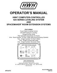
<strong>HWH</strong> R<br />
CORPORATION<br />
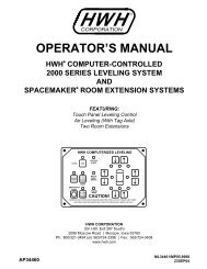
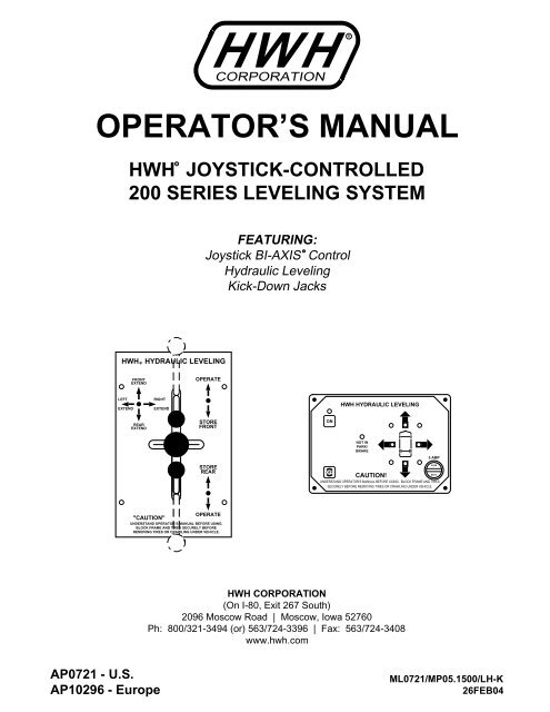
OPERATOR’S MANUAL<br />
<strong>HWH</strong> JOYSTICK-CONTROLLED<br />
200 SERIES LEVELING SYSTEM<br />
R<br />
FEATURING:<br />
R<br />
Joystick BI-AXIS Control<br />
Hydraulic Leveling<br />
Kick-Down Jacks<br />
<strong>HWH</strong> HYDRAULIC LEVELING<br />
FRONT<br />
EXTEND<br />
OPERATE<br />
LEFT<br />
EXTEND<br />
RIGHT<br />
EXTEND<br />
<strong>HWH</strong> HYDRAULIC LEVELING<br />
REAR<br />
EXTEND<br />
STORE<br />
FRONT<br />
ON<br />
NOT IN<br />
PARK/<br />
BRAKE<br />
5 AMP<br />
STORE<br />
REAR<br />
OFF<br />
CAUTION!<br />
UNDERSTAND OPERATOR’S MANUAL BEFORE USING. BLOCK FRAME AND TIRES<br />
SECURELY BEFORE REMOVING TIRES OR CRAWLING UNDER VEHICLE.<br />
FUSE<br />
FUSE<br />
OPERATE<br />
"CAUTION"<br />
UNDERSTAND OPERATOR’S MANUAL BEFORE USING.<br />
BLOCK FRAME AND TIRES SECURELY BEFORE<br />
REMOVING TIRES OR CRAWLING UNDER VEHICLE.<br />
<strong>HWH</strong> CORPORATION<br />
(On I-80, Exit 267 South)<br />
2096 Moscow Road | Moscow, Iowa 52760<br />
Ph: 800/321-3494 (or) 563/724-3396 | Fax: 563/724-3408<br />
www.hwh.com<br />
AP0721 - U.S.<br />
AP10296 - Europe<br />
<strong>ML0721</strong>/MP05.1500/LH-K<br />
26FEB04
OPERATOR’S MANUAL<br />
CAUTION !<br />
READ THE ENTIRE OPERATOR’S MANUAL BEFORE OPERATING.<br />
BLOCK FRAME AND TIRES SECURELY BEFORE CRAWLING UNDER VEHICLE. DO NOT USE LEVELING JACKS OR AIR<br />
SUSPENSION TO SUPPORT VEHICLE WHILE UNDER VEHICLE OR CHANGING TIRES. VEHICLE MAY DROP AND/OR<br />
MOVE FORWARD OR BACKWARD WITHOUT WARNING CAUSING INJURY OR DEATH.<br />
KEEP ALL PEOPLE CLEAR OF VEHICLE WHILE LEVELING SYSTEM AND ROOM EXTENSION ARE BEING OPERATED.<br />
THE JACKS MAY ABRUPTLY SWING UP WHEN THE FOOT CLEARS THE GROUND OR WHEN JACK REACHES FULL<br />
EXTENSION.<br />
NEVER PLACE HANDS OR OTHER PARTS OF THE BODY NEAR HYDRAULIC LEAKS. OIL MAY PENETRATE SKIN<br />
CAUSING INJURY OR DEATH.<br />
WEAR SAFETY GLASSES WHEN INSPECTING OR SERVICING THE SYSTEM TO PROTECT EYES FROM DIRT, METAL<br />
CHIPS, OIL LEAKS, ETC. FOLLOW ALL OTHER APPLICABLE SHOP SAFETY PRACTICES.<br />
IF THIS VEHICLE IS EQUIPPED WITH KICK-DOWN STYLE JACKS, DO NOT OVER EXTEND THE REAR JACKS. IF<br />
THE WEIGHT OF THE VEHICLE IS REMOVED FROM ONE OR BOTH REAR WHEELS, THE VEHICLE MAY ROLL FOR-<br />
WARD OR BACKWARD OFF THE JACKS.<br />
NOTE: KEEP THE CONTROL VALVE LEVERS IN THE STORE POSITION WHEN JACKS ARE NOT IN USE.<br />
IMPORTANT: IF VEHICLE IS EQUIPPED WITH A ROOM EXTENSION, READ ROOM EXTENSION SECTION BEFORE<br />
OPERATING LEVELING SYSTEM.<br />
HOW TO OBTAIN WARRANTY SERVICE<br />
THIS IS NOT TO BE INTERPRETED AS A STATEMENT OF WARRANTY<br />
<strong>HWH</strong> CORPORATION strives to maintain the highest level of<br />
customer satisfaction. Therefore, if you discover a defect or<br />
problem, please do the following:<br />
FIRST: Notify the dealership where you purchased the<br />
vehicle or had the leveling system installed. Dealership<br />
management people are in the best position to resolve<br />
the problem quickly. If the dealer has difficulty solving<br />
the problem, he should immediately contact the Customer<br />
Service Department, at <strong>HWH</strong> CORPORATION.<br />
SECOND: If your dealer cannot or will not solve the problem,<br />
notify the Customer Service Department:<br />
<strong>HWH</strong> CORPORATION 2096 Moscow Rd. Moscow IA. 52760<br />
(563) 724-3396 OR (800) 321-3494. Give your name and<br />
address, coach manufacturer and model year, date the<br />
coach was purchased, or the date of system installation,<br />
description of the problem, and where you can be reached<br />
during business hours (8:00 a.m. till 5:00 p.m. c.s.t.).<br />
<strong>HWH</strong> CORPORATION personnel will contact you to<br />
determine whether or not your claim is valid. If it is, <strong>HWH</strong><br />
CORPORATION will authorize repair or replacement of the<br />
defective part, either by appointment at the factory or by the<br />
authorization of an independent service facility, to be<br />
determined by <strong>HWH</strong> CORPORATION. All warranty repairs<br />
must be performed by an independent service facility<br />
authorized by <strong>HWH</strong> CORPORATION, or at the<br />
<strong>HWH</strong> CORPORATION factory, unless prior written approval<br />
has been obtained from proper <strong>HWH</strong> CORPORATION<br />
personnel.<br />
MP15<br />
30MAY01
CONTROL IDENTIFICATION<br />
FRONT STORE LEVER<br />
(Operate Position)<br />
<strong>HWH</strong> HYDRAULIC LEVELING<br />
FRONT<br />
OPERATE<br />
EXTEND<br />
LEFT<br />
RIGHT<br />
FRONT STORE LEVER<br />
(Store/Travel Position)<br />
EXTEND<br />
EXTEND<br />
REAR<br />
EXTEND<br />
STORE<br />
FRONT<br />
STORE<br />
REAR<br />
JACK CONTROL LEVER<br />
REAR STORE LEVER<br />
(Store/Travel Position)<br />
"CAUTION"<br />
OPERATE<br />
REAR STORE LEVER<br />
(Operate Position)<br />
UNDERSTAND OPERATOR’S MANUAL BEFORE USING.<br />
BLOCK FRAME AND TIRES SECURELY BEFORE<br />
REMOVING TIRES OR CRAWLING UNDER VEHICLE.<br />
WARNING LIGHTS<br />
(4 - Red)<br />
ON LIGHT<br />
<strong>HWH</strong> HYDRAULIC LEVELING<br />
"ON" BUTTON<br />
"NOT IN<br />
PARK/BRAKE" LIGHT<br />
ON<br />
NOT IN<br />
PARK/<br />
BRAKE<br />
LEVELING LIGHTS<br />
(4 - Yellow)<br />
5 AMP<br />
FUSE<br />
"OFF" BUTTON<br />
OFF<br />
CAUTION!<br />
UNDERSTAND OPERATOR’S MANUAL BEFORE USING. BLOCK FRAME AND TIRES<br />
SECURELY BEFORE REMOVING TIRES OR CRAWLING UNDER VEHICLE.<br />
FUSE<br />
CONTROL CIRCUIT FUSE<br />
(5 Amp)<br />
CONTROL FUNCTIONS<br />
CONTROL BUTTONS<br />
"ON" BUTTON: This is the "ON" button for the leveling system.<br />
It provides control power to operate the electrical relay<br />
on the pump, the LEVELING lights and the 4 red WARNING<br />
lights. It does not control power to the master "JACKS DOWN"<br />
warning light.<br />
"OFF" BUTTON: This button turns off control power to the<br />
leveling system, but not the master WARNING light.<br />
STORE LEVERS: These two levers are used to retract the jacks<br />
into the STORE/TRAVEL position. They must be in the operate<br />
position for leveling.<br />
JACK CONTROL LEVER: Jacks are extended in pairs by<br />
pushing the jack control lever to one of the EXTEND positions.<br />
This movement of the lever activates the pump and directs<br />
hydraulic fluid to the jacks. When the lever is released it will<br />
return to the neutral (center) position, turning off the pump<br />
and stopping jacks in position.<br />
INDICATOR LIGHTS<br />
ON LIGHT: This light indicates the system is on.<br />
"NOT IN PARK/BRAKE" LIGHT: This indicator light is on<br />
when the "ON" button is pushed, but the hand/auto park brake is<br />
not set. The panel will not turn on.<br />
LEVELING LIGHTS: If a yellow LEVELING light is on, that<br />
indicates a side or end of the vehicle is low. Extend the appropriate<br />
jack pairs to put out the yellow light. Only one yellow<br />
LEVELING light should be on at a time. The vehicle is level when<br />
all yellow lights are out.<br />
WARNING LIGHTS: A red WARNING light will be on whenever<br />
the corresponding jack is in the vertical position provided<br />
the ignition switch is in the "ACCESSORY" or "ON" position<br />
and the system is on. Some coaches are equipped with a dash<br />
mounted master "JACKS DOWN" light which will be on when<br />
one or more jacks are in the vertical position, provided the<br />
ignition switch is "ON".<br />
MP25.1520<br />
31JAN97
UNDERSTAND OPERATOR’S MANUAL BEFORE USING.<br />
BLOCK FRAME AND TIRES SECURELY BEFORE<br />
REMOVING TIRES OR CRAWLING UNDER VEHICLE.<br />
OPERATING PROCEDURES<br />
SITE SELECTION<br />
Park with the front of the vehicle facing downhill if possible.<br />
Care must be taken not to raise the rear of the vehicle too high or<br />
the vehicle may roll forward or backward off the jacks. If parking<br />
on soft ground or asphalt paving, wood blocks or pads should<br />
be placed under the jacks.<br />
ROOM EXTENSION PROCEDURES<br />
IMPORTANT: If the vehicle is equipped with a room extension<br />
read this section carefully.<br />
If the vehicle is equipped with kick-down jacks, the wheels MUST<br />
be blocked securely. Do NOT operate any room extension<br />
until the leveling and stabilizing procedure is complete. Do<br />
NOT retract the leveling system until all room extensions are<br />
retracted. NEVER operate the leveling system when any<br />
room extensions are extended.<br />
Refer to the vehicle owners manual for proper operation of<br />
room extensions.<br />
IMPORTANT: Do not use a room extension support when the<br />
vehicle is supported by the leveling system.<br />
LEVELING PROCEDURE<br />
JACK<br />
CONTROL<br />
LEVER<br />
OPERATE POSITION<br />
<strong>HWH</strong> HYDRAULIC LEVELING<br />
LEFT<br />
EXTEND<br />
FRONT<br />
EXTEND<br />
REAR<br />
EXTEND<br />
"CAUTION"<br />
OPERATE<br />
2. Turn ignition switch to "ON" or "ACCESSORY".<br />
RIGHT<br />
EXTEND<br />
1. Place gear selector in the parking position, apply park brake<br />
and block tires securely.<br />
NOTE: If the hand/auto park brake is not set, the "NOT IN<br />
PARK/BRAKE" light will come on while the "ON" button is<br />
pushed. The panel will not turn on if the park brake is not<br />
set.<br />
4. Move the FRONT and REAR STORE LEVERS to the OPERATE<br />
POSITION. Nothing should happen at this time.<br />
OPERATE<br />
STORE<br />
FRONT<br />
STORE<br />
REAR<br />
FRONT<br />
STORE<br />
LEVER<br />
REAR<br />
STORE<br />
LEVER<br />
3. Push the "ON" button on the light plate. The POWER ON<br />
light will be lit.<br />
swings vertical. Check that all jacks have swung to the vertical<br />
position. Place pads under jacks if necessary at this time.<br />
6. A lit yellow LEVEL light indicates that the end, side or corner<br />
of the vehicle is low. Only one yellow LEVEL light should be<br />
lit at a time. If a corner of the vehicle is low a side LEVEL light<br />
will be on by itself.<br />
Move the JACK CONTROL LEVER to the extend position to<br />
extend jack pairs corresponding to a lit yellow light. Extend<br />
jack pairs accordingly until all yellow lights are out. It may take<br />
several movements from side to front, or side to rear to raise<br />
a low corner. If the ground is too uneven, the jacks may not<br />
have enough stroke to level the vehicle. The vehicle may<br />
have to be moved. Remember, if the rear of the vehicle is<br />
lifted too high, the vehicle may roll forward or backward off<br />
the jacks.<br />
7. After the vehicle is level, the jacks not used for leveling may<br />
be extended until they touch the ground. This provides additional<br />
stability against wind and activity in the vehicle. Do this<br />
by pushing the jack control lever to the rear and/or front as needed<br />
to extend any remaining jacks. Do not use the right or left<br />
extend positions.<br />
8. Push the "OFF" button on the light panel.<br />
9. Turn the ignition switch off.<br />
5. Swing the jacks to the vertical position by pushing the center<br />
jack control lever to FRONT EXTEND then REAR EXTEND. The<br />
respective red WARNING light will be lit as soon as the jack<br />
MP35<br />
19NOV07
UNDERSTAND OPERATOR’S MANUAL BEFORE USING.<br />
BLOCK FRAME AND TIRES SECURELY BEFORE<br />
REMOVING TIRES OR CRAWLING UNDER VEHICLE.<br />
OPERATING PROCEDURES<br />
RETRACT PROCEDURES<br />
JACK<br />
CONTROL<br />
LEVER<br />
STORE/TRAVEL POSITION<br />
<strong>HWH</strong> HYDRAULIC LEVELING<br />
LEFT<br />
EXTEND<br />
FRONT<br />
EXTEND<br />
REAR<br />
EXTEND<br />
RIGHT<br />
EXTEND<br />
"CAUTION"<br />
OPERATE<br />
STORE<br />
FRONT<br />
STORE<br />
REAR<br />
OPERATE<br />
FRONT<br />
STORE<br />
LEVER<br />
REAR<br />
STORE<br />
LEVER<br />
EXTEND POSITION<br />
STORE/TRAVEL POSITION<br />
LEVER POSITIONS<br />
JACK POSITIONS<br />
CAUTION: MAKE SURE THAT PEOPLE AND<br />
EQUIPMENT ARE CLEAR OF THE VEHICLE.<br />
1. Move the STORE LEVERS to the STORE/TRAVEL<br />
POSITION. This will allow the jacks to retract. As soon as a<br />
jack foot clears the ground, the jack will swing horizontal and<br />
continue to retract.<br />
CAUTION: THE STORE LEVERS SHOULD BE<br />
KEPT IN THE "STORE" POSITION WHILE TRAVELING TO<br />
KEEP THE JACKS IN THE STORE/TRAVEL POSITION.<br />
2. Visually check that all jacks are in the STORE/TRAVEL<br />
position. With the ignition switch in the "ON" or "ACCESSORY"<br />
position, and the system turned on, the red WARNING lights<br />
and the master "JACKS DOWN" light will be out.<br />
CAUTION: DO NOT RELY SOLELY UPON<br />
THE WARNING LIGHTS. IT IS THE OPERATOR’S<br />
RESPONSIBILITY TO CHECK THAT ALL JACKS<br />
ARE IN THE STORE/TRAVEL POSITION BEFORE<br />
MOVING THE VEHICLE.<br />
3. Push the "OFF" button on the light panel. Turn ignition off<br />
or proceed to travel.<br />
NOTE: If the vehicle is parked or stored with the jacks<br />
extended for an extended period of time and the jacks<br />
fail to retract completely, extend the jacks back down<br />
to the ground then retract the jacks again.<br />
MP35.35<br />
01JUL05
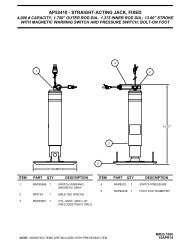
MAINTENANCE<br />
9,000 lb. JACK 16,000 lb. JACK<br />
ROLLER<br />
ASSEMBLY<br />
It is important that all of the jacks are fully retracted before<br />
checking the hydraulic oil level. To check the oil supply, remove<br />
the breather cap from the top of the hydraulic oil reservoir.<br />
The oil level should be approximately one inch below the top of<br />
the reservoir when adequately filled.<br />
On the 9,000 lb. jacks and the 16,000 lb. jacks there are roller assemblies<br />
that need to rotate freely. (See above FIGURE) These<br />
rollers should be cleaned with a penetrating fluid, such as WD-40,<br />
and lubricated with a light oil as part of your regular maintenance<br />
schedule.<br />
FLUID LEVELS<br />
JACK MAINTENANCE<br />
UNUSUAL CONDITIONS<br />
FLUID: <strong>HWH</strong> Specialty Hydraulic Oil is recommended. In an<br />
emergency Dexron automatic transmission fluid can be used.<br />
NOTE: Dexron automatic transmission fluid contains red dye<br />
and can cause staining should a leak occur. DO NOT USE<br />
brake fluid or hydraulic jack fluid. Use of these can damage<br />
seals.<br />
In general, to insure the smooth operation of the leveling system,<br />
it is a good idea to occasionally check the individual leveling<br />
jacks to prevent problems. This is especially true under the unusual<br />
conditions stated in the following:<br />
If driving conditions are unusually muddy, the jacks may become<br />
caked or clogged with mud. This condition may hamper the<br />
proper operation of the leveling system. This problem may be<br />
prevented or remedied by cleaning off each leveling jack if they<br />
become excessively muddy.<br />
In wet or icy weather leveling jacks may become encrusted with<br />
ice. This may cause the leveling system to function improperly.<br />
To eliminate this problem, periodically check the leveling jacks<br />
and break loose any ice which may be causing improper operation.<br />
Do not move the vehicle while the leveling jacks are still in<br />
contact with the ground. However, if this should accidentally<br />
happen, the leveling system was designed to protect itself<br />
from damage in most cases. Place the system in the<br />
STORE mode and then visually check to see if the leveling<br />
jacks have returned to the STORE/TRAVEL POSITION.<br />
NOTE: All major components of the system can be replaced<br />
with rebuilt parts or can be sent to <strong>HWH</strong> CORPORATION to<br />
be rebuilt, when the system is out of warranty.<br />
ELECTRICAL SYSTEM<br />
The batteries should be in good condition and fully charged.<br />
Weak batteries can cause erratic operation. Battery cable<br />
terminals and battery posts and connections should be kept<br />
clean. All electrical connections, especially ground connections,<br />
should be clean, tight, free from corrosion and protected from<br />
weathering.<br />
MP45<br />
01JUN01
MAINTENANCE<br />
SYSTEM ADJUSTMENT<br />
SET SCREW,<br />
HORIZONTAL<br />
ADJUSTMENT<br />
LOWER<br />
ADJUSTING<br />
NUT<br />
UPPER<br />
ADJUSTING<br />
NUT<br />
SET SCREW<br />
6,000 lb. JACKS<br />
ADJUSTING<br />
LOCK NUTS,<br />
VERTICAL<br />
ADJUSTMENT<br />
STANDARD &<br />
LOW PROFILE<br />
UNITS<br />
9,000 lb. JACKS<br />
STOP<br />
ADJUSTING<br />
CAP<br />
HEAVY DUTY<br />
LEVELING<br />
UNITS<br />
16,000 lb. JACKS<br />
There are two basic adjustments which are made at the time<br />
of installation. However, when adjustment of a leveling unit<br />
is needed, the following procedures are recommended.<br />
1. 6,000 lb. JACKS: Always make vertical adjustment first. If<br />
the vertical adjustment is changed at anytime, be sure to check<br />
the horizontal adjustment. Vertical position is changed by adjusting<br />
the lock nuts on the actuator cable. If the jack stopped short<br />
of vertical, tighten the lock nuts. If the jack goes past vertical,<br />
back the lock nuts off. Be sure to adjust each nut the same<br />
number of turns.<br />
NOTE: The two front jacks should be adjusted to the same<br />
horizontal position.<br />
Horizontal stop is adjusted by turning the set screws located<br />
just inside the cable locknuts. The jack can be adjusted down<br />
to provide clearance for objects which may interfere with the<br />
operation of the jacks. The horizontal stop must be adjusted<br />
to provide clearance between the hat bracket and mounting<br />
bolts; and the actuator and hose fittings, when the jack is in<br />
the STORE POSITION. The jack must be able to fully extend<br />
in the horizontal position without interfering with suspension components,<br />
tanks, etc.<br />
JACK ADJUSTMENT<br />
LEVEL SENSING UNIT ADJUSTMENT<br />
2. 9,000 lb. JACKS: Each jack should be checked to be sure<br />
that it is vertical when it swings down. To do this, retract all<br />
jacks, then extend each jack until it is close to, but not touching<br />
the ground. If the jack stopped short of being vertical, it can<br />
be adjusted by loosening the lower adjusting nut and tightening<br />
the upper nut.<br />
The horizontal stop can be adjusted up or down in the slot to<br />
provide clearance for objects which may interfere with operation<br />
of the jack. The stop must be adjusted so that the jack can be<br />
fully extended in the horizontal position without interfering with<br />
suspension components, tanks, etc.<br />
3. 16,000 lb. JACKS: If the jack stopped short of being vertical<br />
loosen the set screw and turn the adjusting cap clockwise.<br />
If the jack went beyond vertical, loosen the set screw and turn<br />
the adjusting cap counterclockwise. After each adjustment,<br />
the weight of the vehicle must be applied to the jack to make<br />
the adjustment effective. DO NOT adjust cap more than one<br />
turn without cycling the jack.<br />
The horizontal stop on the heavy-duty jack is adjusted by adding<br />
washers under the urethane stop.<br />
Level the vehicle by placing a circular bubble level in the<br />
center of the freezer floor or location within the vehicle that<br />
is to be level. With the vehicle level, adjust the sensing unit<br />
until all yellow lights are off. This is done by drawing up the<br />
corresponding screw if the sensing unit is mounted below<br />
the surface as shown or backing out the corresponding<br />
screw if the sensing unit is mounted above the surface.<br />
Bump the sensing unit to see that it is settled tight against<br />
all three screw heads and still indicates that the unit is level.<br />
ELECTRONIC LEVEL SENSING UNIT<br />
BELOW THE SURFACE MOUNTING<br />
FRONT<br />
THIS<br />
SIDE<br />
UP<br />
MOUNTING SURFACE<br />
SPRINGS (3)<br />
SCREWS (3)<br />
MP45.0<br />
13FEB03
TROUBLE SHOOTING<br />
210/225 SERIES BI-AXIS VALVE<br />
The following is a list of problems, and possible solutions, which might occur to the leveling system.<br />
NOTE: Only qualified technicians should install or repair leveling systems on vehicles. A knowledge of hydraulics, welding, the<br />
vehicle’s suspension and electrical system, as well as an understanding of the leveling system’s hydraulics and electronics<br />
is required.<br />
1. JACK RETRACTS AFTER COACH IS LEVEL.<br />
A. Hose or jack has external leak.<br />
B. Fluid is leaking back to reservoir through control valve.<br />
2. LEVELING JACKS WILL NOT RETRACT COMPLETELY.<br />
A. Actuator rod bent or scored (rod will not move freely).<br />
B. Jack clogged with mud or ice.<br />
C. Main rod bent or scored.<br />
D. Valve plunger not completely depressed by valve handle.<br />
E. Springs weak or broken.<br />
F. Hydraulic line pinched.<br />
3. UNIT IS EXTENDED BUT NOT VERTICAL.<br />
A. Move the store lever to the "STORE" position and wait two<br />
minutes. Be sure the jack is fully retracted, then try again.<br />
B. Roller assembly frozen or missing.<br />
C. Actuator rod bent.<br />
D. Actuator not functioning properly.<br />
4. IGNITION SWITCH ON, BUT NO POWER TO PUMP AND/<br />
OR LIGHTS.<br />
A. Park brake not set.<br />
B. 12 or 24 volts (as applicable) from main<br />
power source not present.<br />
C. Faulty PC board.<br />
D. Faulty wire or electrical connection.<br />
5. PUMP WILL NOT ACTIVATE.<br />
A. Grounding switch on valve not working.<br />
B. Pump relay not functioning.<br />
C. Pump not grounded.<br />
6. HYDRAULIC PUMP ACTIVATES WITHOUT USE OF<br />
CONTROL VALVE HANDLES.<br />
A. Grounding switch at valve shorted.<br />
B. Pump relay stuck.<br />
C. Relay control wire shorted to ground.<br />
7. HYDRAULIC PUMP ACTIVATES, BUT THE JACKS<br />
WILL NOT EXTEND.<br />
A. Store levers not in the operate position.<br />
B. Oil supply low in reservoir.<br />
C. Pump is not developing pressure.<br />
D. Broken hydraulic line.<br />
8. LEVELING LIGHTS (YELLOW) NOT FUNCTIONING<br />
PROPERLY.<br />
A. Yellow lights will not go out when vehicle is level:<br />
adjust sensing unit.<br />
B. If two or more lights are on replace PC board and<br />
check sensing unit<br />
9. WARNING LIGHTS (RED) NOT FUNCTIONING<br />
PROPERLY.<br />
A. Light will not come on: check for broken wire at<br />
warning switch on the jack.<br />
B. Lights will not go out bad warning switch or wires<br />
are shorted to ground.<br />
C. Check PC board.<br />
MP55<br />
28AUG07
HYDRAULIC LINE<br />
CONNECTION DIAGRAM<br />
200/210/225 SERIES BI-AXIS VALVE<br />
NOTE: Hose fittings at the pump will come directly<br />
out of the pump or if equipped with a room manifold,<br />
out of the top of the room manifold.<br />
FRONT<br />
PRESSURE<br />
BREATHER/<br />
FILLER CAP<br />
RETURN<br />
LF<br />
RF<br />
PRESSURE<br />
LEFT FRONT<br />
JACK<br />
RIGHT FRONT<br />
JACK<br />
RETURN<br />
LEFT REAR<br />
JACK<br />
RIGHT REAR<br />
JACK<br />
LR<br />
RR<br />
MP65<br />
04FEB03
LEFT<br />
RAISE<br />
FRONT<br />
RAISE<br />
REAR<br />
RAISE<br />
RIGHT<br />
RAISE<br />
UNDERSTAND OPERATOR’S MANUAL BEFORE USING.<br />
BLOCK FRAME AND TIRES SECURELY BEFORE<br />
REMOVING TIRES OR CRAWLING UNDER VEHICLE.<br />
FUSE<br />
FUSE<br />
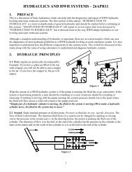
ELECTRICAL CONNECTION DIAGRAM<br />
200 SERIES LEVELING SYSTEM<br />
<strong>HWH</strong> HYDRAULIC LEVELING<br />
"CAUTION"<br />
OPERATE<br />
STORE<br />
FRONT<br />
STORE<br />
REAR<br />
OPERATE<br />
MASTER WARNING<br />
LIGHT/BUZZER<br />
CONNECTION DIAGRAM<br />
8600 6230<br />
B A<br />
SEE PANEL<br />
CONNECTION<br />
DIAGRAM<br />
FROM +12 ACC.<br />
FUSE 15 AMP MAX. -<br />
(RED) 6120<br />
<strong>HWH</strong> HYDRAULIC LEVELING<br />
ON<br />
NOT IN<br />
PARK/<br />
BRAKE<br />
5 AMP<br />
OFF<br />
CAUTION!<br />
UNDERSTAND OPERATOR’S MANUAL BEFORE USING. BLOCK FRAME AND TIRES<br />
SECURELY BEFORE REMOVING TIRES OR CRAWLING UNDER VEHICLE.<br />
(BLUE) 9000<br />
SEE PUMP RELAY<br />
CONNECTION DIAGRAM<br />
TO BRAKE<br />
LIGHT ON<br />
DASH - 9001<br />
WIRES ARE<br />
LABELED<br />
TO PARK BRAKE<br />
SWITCH - 9000<br />
LF<br />
RF<br />
B A<br />
(WHITE) 6230<br />
(GRAY)<br />
2000<br />
B A<br />
(ORANGE)<br />
1000<br />
WARNING<br />
SWITCH<br />
WARNING<br />
SWITCH<br />
(WHITE)<br />
6230<br />
ELECTRONIC<br />
SENSING UNIT<br />
THIS<br />
SIDE<br />
UP<br />
FRONT<br />
DO NOT REVERSE WIRE<br />
COLORS OR NUMBERS TO A & B<br />
ON PACKARD CONNECTORS<br />
NOTE: THE (4) DIGIT WIRE NUMBER<br />
SUPERSEDES ANY AND ALL WIRE<br />
COLORS.<br />
(WHITE)<br />
6230<br />
LR<br />
A<br />
B<br />
(GREEN)<br />
4000<br />
(WHITE)<br />
6230<br />
B A<br />
(BLACK)<br />
3000<br />
RR<br />
WARNING<br />
SWITCH<br />
WARNING<br />
SWITCH<br />
MP85.1500<br />
20JAN03
ELECTRICAL CONNECTION DIAGRAM<br />
200 SERIES LEVELING SYSTEM<br />
PUMP RELAY CONNECTION DIAGRAM<br />
PUMP MUST BE MOUNTED SOLIDLY TO FRAME. SOME PUMPS HAVE A<br />
GROUND CABLE THAT IS TO BE ATTACHED TO THE GROUND STUD.<br />
NOTE: THE (4) DIGIT WIRE NUMBER SUPERSEDES ANY AND ALL WIRE COLORS.<br />
WIRE FROM<br />
HARNESS -<br />
(BLUE) 6820<br />
BATTERY<br />
+<br />
-<br />
8600<br />
GROUND<br />
* FUSE<br />
FROM VALVE<br />
6230<br />
NOTE : IF THE PUMP BRACKET IS WELDED TO THE<br />
FRAME, USE THE GROUND STUD TO ATTACH THE<br />
THE PUMP TO THE BRACKET. IF THE PUMP BRACKET<br />
IS BOLTED TO THE FRAME, USE THE GROUND STUD<br />
TO ATTACH THE BRACKET TO THE FRAME.<br />
* FUSE MAY BE REQUIRED - CHECK APPLICABLE CODE<br />
WIRES ARE LABELED<br />
DO NOT REVERSE<br />
GROUND STUD<br />
FROM HARNESS<br />
FUSED 10 AMP -<br />
(WHITE) 6230<br />
PANEL CONNECTION DIAGRAM<br />
4-PIN MTA<br />
PARK/BRAKE<br />
5-PIN MTA<br />
SENSING UNIT<br />
REAR RED<br />
RIGHT SIDE GREEN<br />
FRONT BLACK<br />
LEFT SIDE YELLOW<br />
GROUND WHITE<br />
9-PIN MTA<br />
HARNESS<br />
WIRING HARNESS<br />
GROUND - (WHITE) 6230<br />
PUMP - (BLUE) 6820<br />
- WARN. LIGHT - (BROWN) 7699<br />
+ WARN. LIGHT - (PURPLE) 6121<br />
LEFT REAR - (GREEN) 4000<br />
LEFT FRONT - (ORANGE) 1000<br />
RIGHT FRONT - (GRAY) 2000<br />
RIGHT REAR - (BLACK) 3000<br />
NOT USED<br />
(BLUE)<br />
9000<br />
FUSED +12 ACC. POWER<br />
15A. MAX. - (RED) 6120<br />
NOTE: THE (4) DIGIT WIRE<br />
NUMBER SUPERSEDES<br />
ANY AND ALL WIRE COLORS.<br />
MP85.1510<br />
12DEC00
MP85.9925<br />
14JAN99<br />
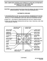
ON<br />
CR1<br />
CR1-1<br />
OFF<br />
2K<br />
2K<br />
ON<br />
430<br />
LIGHT PANEL<br />
CR1-2<br />
NOT IN<br />
PARK<br />
430<br />
TO PARK BRAKE LIGHT<br />
ON DASH - 9001<br />
NC<br />
NEGATIVE<br />
PARK BRAKE<br />
PIGTAIL - 9000<br />
5 AMP<br />
FUSE<br />
12V ACC. -<br />
(RED) 6120<br />
1<br />
2<br />
3<br />
4<br />
5<br />
6<br />
7<br />
8<br />
9<br />
PARK BRAKE<br />
SWITCH<br />
9000<br />
(WHITE) 6230<br />
(BLUE) 6820<br />
(BROWN) 7699<br />
(PURPLE) 6121<br />
LR - (GREEN) 4000<br />
LF - (ORANGE) 1000<br />
RF - (GRAY) 2000<br />
RR - (BLACK) 3000<br />
NC<br />
REAR<br />
RS<br />
FRONT<br />
LS<br />
GND<br />
NC<br />
SENSING<br />
UNIT<br />
POSITIVE<br />
PARK BRAKE<br />
PIGTAIL<br />
PARK BRAKE<br />
SWITCH<br />
* BATTERY<br />
WARNING<br />
SWITCH<br />
-<br />
+<br />
+12<br />
8600<br />
PUMP<br />
RELAY<br />
M<br />
PUMP<br />
VALVE<br />
SWITCH<br />
JACK<br />
DOWN<br />
LIGHT<br />
* FUSE MAY BE REQUIRED<br />
CHECK APPLICABLE CODES<br />
6230<br />
NOTE: THE (4) DIGIT WIRE NUMBER<br />
SUPERSEDES ANY AND ALL WIRE COLORS.<br />
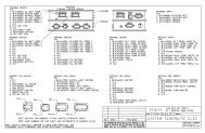
ELECTRICAL SCHEMATIC<br />
200 SERIES LEVELING SYSTEM LIGHT PANEL<br />
KICK-DOWN JACKS WITHOUT AIR DUMP FEATURE
+<br />
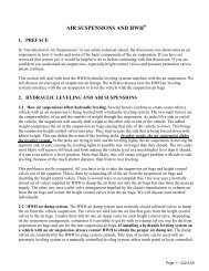
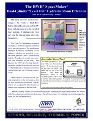
MASTER LIGHT/BUZZER CONNECTION DIAGRAM<br />
MANUAL LEVELING SYSTEMS<br />
A MASTER WARNING INDICATOR SHOULD ALWAYS BE USED. WHEN THE LEVELING SYSTEM HAS STRAIGHT-<br />
ACTING JACKS A WARNING BUZZER MUST BE USED.<br />
WHEN ONLY A RED MASTER WARNING LIGHT IS USED THE 12+ POWER FOR THE LIGHT COMES THROUGH THE<br />
CONTROL PANEL. (SEE FIGURE 1 BELOW.) WHEN BOTH A RED LIGHT AND WARNING BUZZER ARE USED THE<br />
+12 POWER FOR BOTH INDICATORS IS SUPPLIED BY THE IGNITION SWITCH. THE POWER MUST COME FROM<br />
THE "ON" SIDE OF THE IGNITION SWITCH, NOT THE "ACC" SIDE. (SEE FIGURE 2 BELOW)<br />
NOTE: BY SUPPLYING IGNITION POWER TO THE WARNING BUZZER AND LIGHT, AND "ACC" POWER TO THE CONTROL<br />
PANEL, THE SYSTEM MAY BE OPERATED IN ACCESSORY WITHOUT THE BUZZER SOUNDING. THE NEGATIVE SIGNAL<br />
FOR THE WARNING INDICATORS MUST ALWAYS COME FROM THE CONTROL PANEL.<br />
CAUTION: THE PURPLE WIRE IN THE MASTER WARNING LIGHT HARNESS IS HOT WHENEVER THE IGNITION<br />
IS "ON" OR IN "ACC". THE PURPLE WIRE MUST BE REMOVED FROM THE HARNESS WHEN USING DIRECT IGNITION<br />
VOLTAGE FOR THE MASTER WARNING INDICATORS.<br />
NOTE: THE (4) DIGIT WIRE NUMBER SUPERSEDES ANY AND ALL WIRE COLORS.<br />
WARNING LIGHT WIRES ARE INCLUDED<br />
IN 9 OR 11 PIN MTA PLUG<br />
+<br />
-<br />
+12 - (PURPLE) 6121<br />
CONTROL WIRE - (BROWN) 7699<br />
FIGURE 1<br />
SEE PANEL<br />
CONNECTION<br />
DIAGRAM<br />
CONNECT THIS END<br />
TO IGNITION "ON" POWER.<br />
5-15 AMP FUSE<br />
PIGTAIL<br />
W/ DIODE AND IN<br />
LINE FUSE HOLDER<br />
SEE PANEL<br />
CONNECTION<br />
DIAGRAM<br />
BUZZER<br />
6111<br />
JACKS DOWN LIGHT<br />
INCLUDED IN<br />
HARDWARE KIT.<br />
_<br />
NOTE: DO NOT USE<br />
(PURPLE) WIRE - 6121<br />
REMOVE (PURPLE) WIRE - 6121<br />
FROM HARNESS.<br />
NOTE: SPLICE (BROWN) WIRE - 7699<br />
FROM <strong>HWH</strong> LIGHT PLATE TO<br />
(BROWN) - 7699 PIGTAIL<br />
WITH BUTT CONNECTOR.<br />
PIGTAIL<br />
PROVIDED - (BROWN) 7699<br />
FIGURE 2<br />
MP85.9999<br />
13JAN99