ML34461 - HWH Corporation
ML34461 - HWH Corporation
ML34461 - HWH Corporation

Create successful ePaper yourself
Turn your PDF publications into a flip-book with our unique Google optimized e-Paper software.
HCORPORATIONH W<br />
R<br />
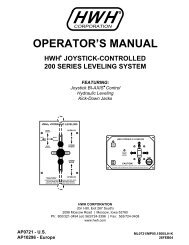
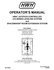
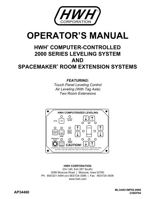
OPERATOR’S MANUAL<br />
<strong>HWH</strong> COMPUTER-CONTROLLED<br />
R<br />
2000 SERIES LEVELING SYSTEM<br />
AND<br />
SPACEMAKER ROOM EXTENSION SYSTEMS<br />
R<br />
FEATURING:<br />
Touch Panel Leveling Control<br />
Air Leveling (With Tag Axle)<br />
Two Room Extensions<br />
<strong>HWH</strong> COMPUTERIZED LEVELING<br />
LEVEL<br />
AIR<br />
EXCESS<br />
SLOPE<br />
TRAVEL<br />
MODE<br />
NOT IN<br />
PARK/<br />
BRAKE<br />
EMERGENCY<br />
STOP<br />
DUMP<br />
RAISE<br />
TRAVEL<br />
MODE<br />
CAUTION!<br />
UNDERSTAND OPERATOR’S MANUAL BEFORE USING. BLOCK FRAME AND TIRES<br />
SECURELY BEFORE REMOVING TIRES OR CRAWLING UNDER VEHICLE.<br />
<strong>HWH</strong> CORPORATION<br />
(On I-80, Exit 267 South)<br />
2096 Moscow Road | Moscow, Iowa 52760<br />
Ph: 800/321-3494 (or) 563/724-3396 | Fax: 563/724-3408<br />
www.hwh.com<br />
AP34460<br />
<strong>ML34461</strong>/MP05.9988<br />
23SEP04
OPERATOR’S MANUAL<br />
CAUTION !<br />
READ THE ENTIRE OPERATOR’S MANUAL BEFORE OPERATING.<br />
BLOCK FRAME AND TIRES SECURELY BEFORE CRAWLING UNDER VEHICLE. DO NOT USE LEVELING JACKS OR AIR<br />
SUSPENSION TO SUPPORT VEHICLE WHILE UNDER VEHICLE OR CHANGING TIRES. VEHICLE MAY DROP AND/OR<br />
MOVE FORWARD OR BACKWARD WITHOUT WARNING CAUSING INJURY OR DEATH.<br />
KEEP ALL PEOPLE CLEAR OF VEHICLE WHILE LEVELING SYSTEM AND ROOM EXTENSION ARE BEING OPERATED.<br />
NEVER PLACE HANDS OR OTHER PARTS OF THE BODY NEAR HYDRAULIC LEAKS. OIL MAY PENETRATE SKIN<br />
CAUSING INJURY OR DEATH.<br />
DO NOT OPERATE THE LEVELING SYSTEM OR USE THE DUMP OR RAISE BUTTONS IF THE VEHICLE IS MOVING<br />
IN EXCESS OF 5 MPH.<br />
WEAR SAFETY GLASSES WHEN INSPECTING OR SERVICING THE SYSTEM TO PROTECT EYES FROM DIRT, METAL<br />
CHIPS, OIL LEAKS, ETC. FOLLOW ALL OTHER APPLICABLE SHOP SAFETY PRACTICES.<br />
IMPORTANT: IF COACH IS EQUIPPED WITH A ROOM EXTENSION, READ ROOM EXTENSION SECTION BEFORE<br />
OPERATING LEVELING SYSTEM.<br />
HOW TO OBTAIN WARRANTY SERVICE<br />
THIS IS NOT TO BE INTERPRETED AS A STATEMENT OF WARRANTY<br />
<strong>HWH</strong> CORPORATION strives to maintain the highest level of<br />
customer satisfaction. Therefore, if you discover a defect or<br />
problem, please do the following:<br />
FIRST: Notify the dealership where you purchased the<br />
vehicle or had the leveling system installed. Dealership<br />
management people are in the best position to resolve<br />
the problem quickly. If the dealer has difficulty solving<br />
the problem, he should immediately contact the Customer<br />
Service Department, at <strong>HWH</strong> CORPORATION.<br />
SECOND: If your dealer cannot or will not solve the problem,<br />
notify the Customer Service Department:<br />
<strong>HWH</strong> CORPORATION 2096 Moscow Rd. Moscow IA. 52760<br />
(563) 724-3396 OR (800) 321-3494. Give your name and<br />
address, coach manufacturer and model year, date the<br />
coach was purchased, or the date of system installation,<br />
authorization of an independent service facility, to be<br />
defective part, either by appointment at the factory or by the<br />
CORPORATION will authorize repair or replacement of the<br />
determine whether or not your claim is valid. If it is, <strong>HWH</strong><br />
<strong>HWH</strong> CORPORATION personnel will contact you to<br />
during business hours (8:00 a.m. till 5:00 p.m. c.s.t.).<br />
description of the problem, and where you can be reached<br />
determined by <strong>HWH</strong> CORPORATION. All warranty repairs<br />
must be performed by an independent service facility<br />
authorized by <strong>HWH</strong> CORPORATION, or at the<br />
<strong>HWH</strong> CORPORATION factory, unless prior written approval<br />
has been obtained from proper <strong>HWH</strong> CORPORATION<br />
personnel.<br />
MP15.4501<br />
30MAY01
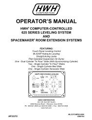
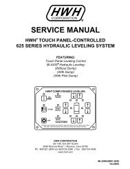
CONTROL IDENTIFICATION<br />
"EXCESS SLOPE"<br />
LIGHT<br />
"NOT IN PARK"<br />
LIGHT<br />
LEVELING SYSTEM<br />
ACTIVE LIGHT<br />
"AIR" (ON) BUTTON<br />
DUMP LIGHT<br />
"TRAVEL MODE" BUTTON<br />
LIGHT (Red)<br />
"TRAVEL MODE" BUTTON<br />
"DUMP" BUTTON<br />
"EMERGENCY STOP" BUTTON<br />
RAISE LIGHT<br />
"RAISE" BUTTON<br />
"TRAVEL MODE"<br />
LIGHT (Green)<br />
CONTROL BUTTONS<br />
TRAVEL<br />
MODE<br />
EMERGENCY<br />
STOP<br />
RAISE LEFT SIDE<br />
BUTTON<br />
<strong>HWH</strong> COMPUTERIZED LEVELING<br />
AIR<br />
DUMP<br />
RAISE<br />
EXCESS<br />
SLOPE<br />
NOT IN<br />
PARK /<br />
BRAKE<br />
TRAVEL<br />
MODE<br />
CAUTION!<br />
UNDERSTAND OPERATOR’S MANUAL BEFORE USING. BLOCK FRAME AND TIRES<br />
SECURELY BEFORE REMOVING TIRES OR CRAWLING UNDER VEHICLE.<br />
LOWER LEFT SIDE<br />
BUTTON<br />
CONTROL FUNCTIONS<br />
HARD RESET SWITCH<br />
(SEE <strong>HWH</strong> LIGHTED RESET SWITCH)<br />
MASTER WARNING LIGHT<br />
LOWER FRONT BUTTON<br />
RAISE FRONT BUTTON<br />
WARNING LIGHTS<br />
(4 - Red)<br />
RAISE RIGHT SIDE BUTTON<br />
LOWER RIGHT SIDE BUTTON<br />
LEVELING LIGHTS<br />
(4 - Yellow)<br />
RAISE REAR BUTTON<br />
LOWER REAR BUTTON<br />
INDICATOR LIGHTS<br />
"AIR" BUTTON: This is the system active and automatic<br />
operation button. It works if the ignition is in the "ON" position.<br />
"EMERGENCY STOP" BUTTON: This button turns the<br />
system OFF but does NOT control power to the "DUMP" or<br />
"RAISE" buttons. Pushing this button will NOT put the system<br />
in the TRAVEL mode.<br />
"TRAVEL MODE" BUTTON: This button will put the Leveling<br />
System in the TRAVEL mode. The ignition must be "ON" for<br />
the vehicle to return to proper ride height for traveling.<br />
"DUMP" BUTTON: This button will lower the whole coach by<br />
dumping air from the suspension system.<br />
"RAISE" BUTTON: This button will raise the whole coach<br />
by adding air to the suspension system.<br />
IMPORTANT: Read "DUMP AND RAISE FUNCTIONS"<br />
before using the "DUMP" or "RAISE" buttons.<br />
UP ARROWS (RAISE BUTTONS): These momentary<br />
buttons are used for manually operating the air leveling<br />
systems. Sides or ends of the vehicle will raise while these<br />
buttons are pushed.<br />
DOWN ARROWS (LOWER BUTTONS): These momentary<br />
buttons are used for manually operating the air leveling<br />
systems. Sides or ends of the vehicle will lower while these<br />
buttons are pushed.<br />
LEVEL SYSTEM ACTIVE LIGHT: ON when the system is<br />
active, and flashes during automatic leveling.<br />
DUMP LIGHT: Flashes when "DUMP" button is pushed.<br />
RAISE LIGHT: Flashes when "RAISE" button is pushed.<br />
"EXCESS SLOPE" LIGHT: ON if the leveling system<br />
can NOT level the coach.<br />
"TRAVEL MODE" BUTTON LIGHT (RED): Light flashes<br />
for 3 seconds after the "TRAVEL MODE" button is pushed.<br />
"TRAVEL MODE" LIGHT (GREEN): ON if the ignition is in<br />
the "ON" position, the system is not being used, and there is<br />
sufficient air pressure in the suspension.<br />
See PREPARATION FOR TRAVEL.<br />
WARNING LIGHTS: Function with the ignition in the<br />
"ON" position. ON when the LEVELING SYSTEM ACTIVE<br />
LIGHT is ON. See PREPARATION FOR TRAVEL.<br />
LEVELING LIGHTS: One or two yellow lights can be on<br />
indicating the side, end or corner of the coach is low.<br />
"NOT IN PARK/BRAKE" LIGHT: ON while the "AIR" button<br />
is being pushed if the Park Brake is NOT set. The light will go<br />
out when the "AIR" button is released.<br />
MASTER WARNING LIGHT: ON any time the<br />
"TRAVEL" light is not ON, if the ignition is in the<br />
"ON" position.<br />
MP25.998D<br />
31OCT02
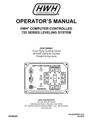
CONTROL IDENTIFICATION<br />
ROOM EXTENSION OPERATOR’S PANEL<br />
PUMP ON INDICATOR<br />
LIGHT (RED)<br />
KEY SWITCH<br />
PUMP ON<br />
HYDRAULIC ROOM EXTENSION<br />
OFF<br />
<strong>HWH</strong><br />
R<br />
CORPORATION<br />
FLASH / WAIT<br />
STEADY / READY TO<br />
OPERATE<br />
EXTEND<br />
READY TO OPERATE<br />
LIGHT (AMBER)<br />
ROOM CONTROL<br />
SWITCH<br />
ON<br />
CAUTION!<br />
UNDERSTAND OPERATOR’S MANUAL BEFORE<br />
USING. KEEP PEOPLE AND OBSTRUCTIONS<br />
CLEAR OF ROOM WHEN OPERATING.<br />
RETRACT<br />
CONTROL FUNCTIONS<br />
KEY SWITCH: The KEY SWITCH controls power to the ROOM<br />
CONTROL SWITCH. When the KEY SWITCH is in the "ON"<br />
POSITION the room can be operated, and the key cannot be<br />
removed. When the KEY SWITCH is in the "OFF" position<br />
the room cannot be operated, and the key can be removed.<br />
NOTE: Any time the KEY SWITCH is ON, the network will<br />
be active and will not power down.<br />
ROOM CONTROL SWITCH: The ROOM CONTROL SWITCH<br />
is a two position momentary switch. Pressing the switch in the<br />
EXTEND POSITION will extend the room. Pressing the switch<br />
in the RETRACT POSITION will retract the room. Releasing<br />
the ROOM CONTROL SWITCH will halt the operation of the<br />
room.<br />
PUMP ON INDICATOR LIGHT: This light will be on when the<br />
pump is running.<br />
READY TO OPERATE LIGHT: After the KEY SWITCH<br />
is turned on the READY TO OPERATE LIGHT will glow<br />
steady. Except for EXCESS SLOPE situations, the room<br />
cannot be extended or retracted if this light is flashing.<br />
If the "EXCESS SLOPE" light on the leveling system<br />
control panel is on, the READY TO OPERATE light will flash<br />
continously after the key switch is turned ON. The room<br />
will not extend. The room will retract if the room control<br />
switch is pushed to "RETRACT".<br />
If the PARK BRAKE is not set, the READY TO OPERATE<br />
light will not turn on and flash when the KEY SWITCH is<br />
turned "ON".<br />
If a RAISE or LOWER function of the Leveling System is in<br />
use, MANUAL or AUTOMATIC operation, the READY TO<br />
OPERATE light will flash if the KEY SWITCH is in the "ON"<br />
position. The room will not operate.<br />
MASTER WARNING LIGHT<br />
This light is on the dash, separate from the control panels.<br />
It can be on only if the ignition key is in the "ON" position.<br />
The light will be on if a <strong>HWH</strong> low air pressure switch is on,<br />
if the Leveling System is on, or if the Leveling System is not<br />
in the TRAVEL mode.<br />
MP25.998J<br />
19JUN02
CONTROL IDENTIFICATION<br />
PUMP RUN TIME<br />
SYSTEM VARIATIONS FOR PUMP RUN TIME<br />
PUMP RUN TIME<br />
Pump motors used with <strong>HWH</strong> leveling systems and room extension systems come in 3 different diameters; 3", 3.7" and 4.5".<br />
Contact the vehicle manufacturer or <strong>HWH</strong> for help with identifying the motor size. It is important that any time the pump<br />
runs for more than four minutes with a 3" motor; or six minutes with a 3.7" or 4.5" motor that the motor is allowed<br />
to cool for thirty minutes before continuing. Continuous operation of the pump motor without allowing the motor<br />
to cool can damage the motor. For cold weather information see "COLD WEATHER OPERATIONS" below.<br />
The <strong>HWH</strong> systems with a computer processor monitor the pump run time and will turn the pump off if the run time exceeds a<br />
specified time. This time can vary with different systems. Due to available electronics or system design, the pump run time<br />
programs will also vary. Leveling systems and room extensions that are not controlled by a system processor have no pump<br />
run time protection. DO NOT run the pump more than four or six minutes without allowing the pump motor to cool for<br />
thirty minutes.<br />
Some systems with rooms run the rooms separate from the system processor. These systems do not monitor pump<br />
run time when operating the rooms. DO NOT run the pump more than four or six minutes without allowing the<br />
pump motor to cool for thirty minutes.<br />
Some systems can be turned back on immediately after the processor turns the pump off. DO NOT turn the system<br />
back on or run the pump without allowing the pump motor to cool for thirty minutes.<br />
When operating some leveling systems manually or operating the room extensions, the pump will turn off and back<br />
on while pushing the control button when the pump run time has been exceeded. DO NOT continue without allowing<br />
the pump motor to cool for thirty minutes.<br />
With some systems, when the processor has turned the pump off because the run time has been exceeded, power<br />
to the <strong>HWH</strong> system must be turned off and back on before the system will operate. With motorized vehicles, turn the<br />
ignition off and back on. With non-motorized vehicles, turn the master power switch for the <strong>HWH</strong> system off and back<br />
on. DO NOT continue without allowing the pump motor to cool for thirty minutes.<br />
Some <strong>HWH</strong> systems are equipped with a lighted reset switch.<br />
If the processor turns the pump off because the run time has<br />
been exceeded, the light in the reset switch will turn on. The<br />
system will not operate until the reset switch is pushed.<br />
DO NOT continue without allowing the pump motor to<br />
cool for thirty minutes.<br />
LIGHTED RESET SWITCH<br />
No matter what <strong>HWH</strong> system is on the vehicle, the pump should not be ran for more than four minutes<br />
(3" motors) or six minutes (3.7" or 4.5" motors) without allowing the pump motor to cool for thirty minutes.<br />
Continuous operation of the pump motor without allowing the motor to cool can damage the pump motor.<br />
Contact <strong>HWH</strong> corporation to get specific information about the system in this vehicle.<br />
COLD WEATHER OPERATIONS<br />
<strong>HWH</strong> leveling and room extension systems are designed to function in cold weather down to 0 degrees Fahrenheit. Below<br />
freezing (32 degrees Fahrenheit) the jacks or rooms will operate slower than usual.<br />
For operation in temperatures dropping below -20 degrees Fahrenheit, it is necessary that the system is equipped with oil<br />
designed for extreme cold weather application such as a synthetic oil. (Contact <strong>HWH</strong> for recommendations.)<br />
DO NOT run the pump motor continuously. It is important that any time the pump runs for more than four minutes<br />
with a 3" motor; or six minutes with a 3.7" or 4.5" motor that the motor is allowed to cool for thirty minutes before<br />
continuing. Continuous operation of the pump motor without allowing the motor to cool can damage the motor.<br />
Continuous operation of the pump with slow moving jacks or rooms in cold weather, without allowing the pump motor to<br />
cool will cause the pump motor to burn up and damage the pump assembly.<br />
MP25.9995<br />
14MAR12
OPERATING PROCEDURES<br />
NETWORK INFORMATION<br />
The <strong>HWH</strong> 2000 series CAN system is a computerized<br />
modular network. It controls all functions of the leveling<br />
system and the room extensions. The network is active any<br />
time the ignition is in the "ON" or "ACC" position or when<br />
any room extension control panel key is "ON". Certain<br />
functions and indicator lights for the leveling system will work<br />
when the network is active. Certain functions and lights will<br />
work ONLY if the the ignition is in the "ON" or "ACC" position<br />
to start the function.<br />
NOTE: The network will stay active for 10 minutes after the<br />
ignition key and all room extension control panel keys have<br />
been turned "OFF". If the leveling system was turned "ON",<br />
the network will stay active for 10 minutes after automatic<br />
leveling is complete or the system goes "EXCESS SLOPE".<br />
If manual leveling buttons were used, the network stays<br />
active for 10 minutes after the last manual button is released.<br />
GENERAL INSTRUCTIONS<br />
Maintain adequate clearance in all directions for vehicles,<br />
room extensions, doors, steps, etc.. Vehicle may move in any<br />
direction due to raising or lowering of vehicle during leveling,<br />
settling of vehicle, equipment malfunction, etc..<br />
The MASTER WARNING LIGHT will be on if an air bag has<br />
low pressure, if the ignition is in the "ON" position.<br />
CAUTION: DO NOT MOVE THE VEHICLE IF A ROOM IS<br />
EXTENDED. DO NOT MOVE THE VEHICLE AT SPEEDS<br />
IN EXCESS OF 5 MPH IF THE MASTER WARNING LIGHT<br />
IS ON.<br />
The "DUMP" and "RAISE" buttons will function with the<br />
leveling system and park brake off, if the ignition is in the<br />
"ON" or "ACC" position or if the network is active. See AIR<br />
DUMP AND RAISE FUNCTIONS section of this manual.<br />
If the Park Brake is not set, the Leveling System cannot<br />
be turned ON and the room extension will not operate.<br />
If a ROOM CONTROL SWITCH is being pushed, no other<br />
room or the Leveling System can be operated. If any Leveling<br />
System raise or lower function is being operated, no room<br />
control switch will work.<br />
<strong>HWH</strong> LIGHTED RESET SWITCH<br />
The <strong>HWH</strong> lighted reset switch is located on the vehicle dash.<br />
If there is a failure at any time in the <strong>HWH</strong> CAN network, the<br />
network will shut down. The leveling system and all room<br />
extensions will not operate. If the ignition is off, no indicator<br />
lights will come on. If the ignition is in the "ON" or "ACC"<br />
position, the lighted reset switch and the MASTER WARNING<br />
Light will come on.<br />
If the lighted reset switch is on, the switch must be pushed<br />
before any room or the leveling system can be operated.<br />
A network problem with one room will not inhibit the use of<br />
the other rooms or leveling system after the reset switch is<br />
pushed.<br />
A network problem with the leveling system will not inhibit<br />
the use of the room extensions after the reset switch is<br />
pushed.<br />
If the lighted reset switch will not go out when pushed, there<br />
is a problem with the central control module of the network<br />
system. No rooms or the Leveling System will operate.<br />
The vehicle suspension will return to the travel mode if the<br />
ignition key is in the "ON" position.<br />
CAUTION: IF THE IGNITION IS IN THE "ON" POSITION<br />
AND THE LIGHTED RESET SWITCH IS ON, THE VEHICLE<br />
CAN RETURN TO RIDE HEIGHT WITHOUT RELEASING<br />
THE PARK BRAKE.<br />
MP35.103C<br />
25SEP01
OPERATING PROCEDURES<br />
Check that all room extensions are fully retracted.<br />
DO NOT move the vehicle unless the room extensions<br />
are retracted.<br />
Visually check that the vehicle is at the proper ride height for<br />
traveling.<br />
The ignition must be in the "ON" position for the vehicle<br />
suspension to be in the travel mode. Also the "TRAVEL<br />
MODE" button must be pushed or the park brake released<br />
for the suspension to be in the travel mode if the Leveling<br />
System was used.<br />
A lit "TRAVEL MODE" LIGHT indicates that the <strong>HWH</strong><br />
Leveling System is in the TRAVEL MODE. It does not<br />
indicate that the suspension is at ride height or that the<br />
coach is ready to travel.<br />
PREPARATION FOR TRAVEL<br />
CAUTION: IT IS THE OPERATOR’S<br />
RESPONSIBILITY TO CHECK THAT THE VEHICLE IS AT<br />
PROPER RIDE HEIGHT AND THE SLIDE-OUT IS FULLY<br />
RETRACTED BEFORE TRAVELING.<br />
Before traveling, the MASTER WARNING light must be off<br />
and the "TRAVEL MODE" light must be ON.<br />
NOTE: Low air pressure can turn the green<br />
"TRAVEL MODE" light off and turn the<br />
MASTER WARNING light on.<br />
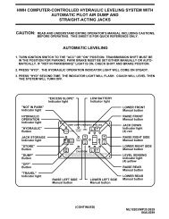
AUTOMATIC AIR OPERATION<br />
Refer to "DUMP" and "RAISE" FUNCTIONS operating<br />
procedures when moving the vehicle with the suspension<br />
NOT at the proper ride height.<br />
NOTE: The ignition must be in the "ON" or "ACC"<br />
position to use the "AIR" button. Once the operation is<br />
started, the ignition can be moved to the "OFF" position<br />
and the operation will continue. If a ROOM CONTROL<br />
switch is being pushed, the Leveling System can not be<br />
operated.<br />
1. Place the transmission in the proper position for parking<br />
and set the park brake. The air leveling system can only be<br />
turned on if the ignition is in the "ON" or "ACC" position.<br />
Leaving the engine running during leveling is recommended.<br />
This will provide a better air supply for leveling.<br />
NOTE: If the TAG DUMP SWITCH is in the DUMP<br />
position, it is recommended that it is returned to the<br />
TRAVEL position before starting the leveling procedure.<br />
2. Press the "AIR" button once to enter the air mode. The<br />
LEVELING SYSTEM ACTIVE LIGHT will glow steady.<br />
The four red WARNING lights on the panel will come on.<br />
This indicates that the height control valves have been<br />
locked out. The vehicle should not be moved when these<br />
lights are on.<br />
NOTE: If the park brake is not set, the "NOT IN<br />
PARK/BRAKE" light will be on while the "AIR" button<br />
is being pushed.<br />
3. Press the "AIR" button a second time. The LEVELING<br />
SYSTEM ACTIVE LIGHT will start flashing and air leveling<br />
will begin. The system will attempt to level the vehicle by<br />
exhausting air from the air bags. If a level position is not<br />
achieved by lowering the vehicle, the low side and/or end of<br />
the vehicle will be raised by adding air to the air bags.<br />
When all four yellow LEVEL SENSING lights are out the<br />
leveling is complete.<br />
NOTE: Only one or two yellow LEVEL SENSING lights<br />
may be ON at one time.<br />
4. When all four yellow level lights are out, the LEVELING<br />
SYSTEM ACTIVE LIGHT will stop flashing and start pulsating<br />
dimly. The Leveling System is now in the SLEEP MODE.<br />
The vehicle’s engine/ignition may now be turned OFF.<br />
NOTE: After the ignition and all room extension KEY<br />
SWITCHES are turned OFF, the CAN Network stays<br />
active for 10 minutes before shutting down. Leveling<br />
System touch panel lights will stay ON during this time<br />
and go out when the CAN Network shuts down. If the<br />
Leveling System is in the SLEEP MODE when the<br />
Network shuts down, the computer will stay ON. The<br />
Leveling System touch panel lights will all be OFF, but<br />
the Leveling System will still be in the SLEEP MODE.<br />
5. During the Sleep Mode, after 30 minutes the processor<br />
checks the Level Sensing Unit inputs. If no input for a<br />
yellow level light is seen, the processor remains dormant<br />
and will recheck the level unit inputs every 30 minutes. If<br />
the yellow light input stays on for one minute continuously,<br />
the processor will relevel the vehicle. If a yellow level light<br />
input is flickering, the processor will monitor the level<br />
sensing unit inputs continuously. If the yellow light input<br />
stays off for one minute, the processor reverts to checking<br />
the inputs every 30 minutes.<br />
NOTE: No lights, including yellow level lights, on the<br />
Touch Panel will be ON unless the Network is actively<br />
trying to level the vehicle.<br />
6. If the vehicle needs to be releveled, the CAN Network will<br />
become active. The LEVELING SYSTEM ACTIVE LIGHT<br />
will flash. One or two yellow LEVELING LIGHTS will be ON.<br />
When the yellow LEVELING LIGHTS are all out, the<br />
LEVELING SYSTEM ACTIVE LIGHT will stop flashing and<br />
start pulsating dimly. The Leveling System will remain in the<br />
SLEEP MODE with the computer monitoring the LEVELING<br />
SENSING UNIT every 30 minutes,<br />
releveling the vehicle as needed.<br />
MP35.203C<br />
12DEC03
OPERATING PROCEDURES<br />
AUTOMATIC AIR OPERATION (Continued)<br />
NOTE: The CAN Network will stay active for 10 minutes<br />
after releveling the vehicle and then shut down, turning the<br />
touch panel lights OFF. This happens every time the system<br />
relevels the vehicle.<br />
7. The SLEEP MODE will continue until the "EMERGENCY<br />
STOP" button is pushed or the park brake is released, if the<br />
ignition is in the "ON" position.<br />
EXCESS SLOPE: The system will attempt to level the<br />
vehicle for approximately 15 to 20 minutes. After the 15 to 20<br />
minutes, if a LEVEL SENSING light is still on, the "EXCESS<br />
SLOPE" light will come on. The LEVEL LIGHT indicator light<br />
will go out. The "EXCESS SLOPE" light will be on whenever<br />
the network is active.<br />
The "EXCESS SLOPE" light will be on whenever the network<br />
is active until the vehicle is leveled with all yellow LEVEL<br />
indicator lights off.<br />
TAG AXLE DUMP<br />
The tag axle dump switch is supplied by Country Coach.<br />
IMPORTANT: Refer to Country Coach for proper use of the<br />
TAG DUMP feature.<br />
The tag dump switch will work only with the ignition switch<br />
in the "ON" position and the Leveling System panel off. The<br />
transmission must be in the R, N or 1 position.<br />
NOTE: If the TAG DUMP switch is in the DUMP position and<br />
the ignition key is turned ON (with the Leveling System panel<br />
OFF) the tag axle air bags will go into the dump mode.<br />
The TAG DUMP switch, in either the DUMP or TRAVEL<br />
position, will not interfere with any air leveling operations.<br />
MP35.303C<br />
25SEP01
OPERATING PROCEDURES<br />
MANUAL AIR OPERATION<br />
NOTE: The ignition must be in the "ON" or "ACC"<br />
position to use the "AIR" button. Once the operation<br />
is started, the ignition can be moved to the "OFF"<br />
position and the operation will continue.<br />
1. Place the transmission in the proper position for parking<br />
and set the park brake. The air leveling system can only be<br />
turned on if the ignition is in the "ON" position. Running the<br />
vehicle engine during leveling is recommended. This will<br />
provide a better air supply for leveling. The vehicle will level<br />
with the engine shut off, however more time will be required<br />
for leveling.<br />
NOTE: If the "NOT IN PARK/BRAKE" light is on,<br />
the leveling system cannot be turned on.<br />
2. Press the "AIR" button once to enter the air mode. The<br />
LEVELING SYSTEM ACTIVE LIGHT indicator light will glow<br />
steady. When the ignition is in the "ON" position, the four red<br />
WARNING lights on the panel will come on. This indicates<br />
that the height control valves have been locked out. The<br />
vehicle should not be moved when these lights are on.<br />
3. The vehicle can now be leveled using the RAISE (up arrow)<br />
and LOWER (down arrow) buttons on the right half of the<br />
panel in conjunction with the yellow LEVEL indicator lights.<br />
Any side to side leveling should be done, if needed,<br />
before leveling the vehicle front to rear. The yellow LEVEL<br />
indicator light indicates that side or end is low. When all yellow<br />
lights are out the vehicle is level. Try leveling the vehicle by<br />
lowering the high side or end (opposite of the lit yellow level<br />
lights). If a level position is not achieved use the RAISE<br />
(up arrow) button to raise the low side or end.<br />
NOTE: In either manual or automatic leveling when<br />
either front air manifold air bag pressure switch is on<br />
a front lower procedure is halted. When either rear air<br />
manifold air bag pressure switch is on, a rear lower<br />
procedure is halted. Air bag pressure switches will<br />
not interfere with either a right or left lower procedure.<br />
4. Turn the ignition to the "OFF" position.<br />
5. Turn the system off.<br />
NOTE: If the "DUMP" or "RAISE" buttons are pushed<br />
while manually leveling the vehicle with air and the<br />
ignition is in the "ON" position, the system will latch<br />
into the dump or raise mode until the "EMERGENCY<br />
STOP" button is pushed or the ignition is turned off.<br />
"DUMP" AND "RAISE" FUNCTIONS<br />
The "DUMP" and "RAISE" functions are provided for operator<br />
convenience for purposes such as dumping the air<br />
suspension when parked.<br />
Leave the engine running if the "RAISE" function is to be<br />
used. The park brake does not have to be set to use the<br />
"DUMP" or "RAISE" buttons.<br />
IMPORTANT: If the ignition is ON and the park brake is<br />
OFF, the "DUMP" and "RAISE" features will latch in and<br />
remain on. If the vehicle exceeds 10 MPH, the "DUMP"<br />
or "RAISE" functions will automatically turn off and the<br />
system will return to the TRAVEL MODE. If the park<br />
brake is set, the "TRAVEL MODE" button must be<br />
pushed before the vehicle can return to ride height.<br />
CAUTION: REREAD CAUTIONS ON THE FIRST<br />
PAGE OF THIS MANUAL. THE VEHICLE MAY DROP OR<br />
RAISE AND/OR MOVE FORWARD OR BACKWARD<br />
WITHOUT WARNING CAUSING INJURY OR DEATH.<br />
DO NOT OPERATE THE VEHICLE UNLESS<br />
THE AIR SUSPENSION IS AT THE PROPER<br />
HEIGHT FOR TRAVEL.<br />
The "RAISE" and "DUMP" buttons can be used at any time<br />
the network is active. The park brake does not have to be on.<br />
If the ignition is in the "ON" position and the park brake is off,<br />
the "RAISE" or "DUMP" buttons will latch in. The vehicle will<br />
raise or lower completely and stay in that position.<br />
The vehicle can not return to ride height until the "TRAVEL<br />
MODE" button or the "EMERGENCY STOP" button is pushed<br />
or the vehicle exceeds 10 M.P.H, putting the system in the<br />
TRAVEL MODE.<br />
If the ignition is in the "OFF" position the "RAISE" and<br />
"DUMP" buttons will not latch in. The vehicle will remain in<br />
the position it was when the button was released. The<br />
vehicle can return to ride height when the ignition is turned<br />
to "ON" if the park brake is released or the "TRAVEL MODE"<br />
button is pushed.<br />
DO NOT operate the vehicle for extended distances<br />
unless the air suspension is at the proper height for<br />
travel. The vehicle can not return to ride height until<br />
the "EMERGENCY STOP" button is pushed or the<br />
vehicle exceeds 10 MPH, putting the system in the<br />
TRAVEL MODE.<br />
CAUTION: IT IS THE OPERATOR’S<br />
RESPONSIBILITY TO CHECK THAT THE VEHICLE<br />
IS AT PROPER RIDE HEIGHT BEFORE TRAVELING.<br />
MP35.485Q<br />
29JUL04
OPERATING PROCEDURES<br />
ROOM EXTEND PROCEDURE<br />
IMPORTANT: It is recommended to level and stabilize<br />
the vehicle before extending the room.<br />
IMPORTANT: Extending or retracting any leveling jacks<br />
when the room is extended is not recommended.<br />
1. The park brake must be set for the room to be operated.<br />
IMPORTANT: If the "EXCESS SLOPE" light is ON,<br />
the vehicle should be re-leveled so all yellow LEVEL<br />
indicator lights on the touch panel are OFF. If any of the<br />
four yellow LEVEL indicator lights cannot be put out, the<br />
vehicle should be moved to a more level location before<br />
using the room extension.<br />
CAUTION: KEEP PEOPLE AND OBSTRUCTIONS<br />
CLEAR OF ROOM WHEN OPERATING.<br />
NOTE: Make sure there is adequate clearance to fully<br />
extend the room.<br />
2. Insert the KEY into the KEY SWITCH on the room<br />
extension operator’s panel and turn it to the "ON" position.<br />
The READY TO OPERATE light will come on steady.<br />
NOTE: If the Leveling System is being operated, the<br />
room will not extend. If the room panel KEY SWITCH is<br />
on, the "READY TO OPERATE" light will flash while the<br />
Leveling System is being operated.<br />
3. To extend the room, push and hold the ROOM CONTROL<br />
SWITCH in the "EXTEND" position. The red "PUMP ON" light will<br />
come on. Hold the ROOM CONTROL SWITCH to "EXTEND"<br />
until the room is fully extended. Releasing the switch will<br />
halt room operation and turn the "PUMP ON" light off.<br />
NOTE: Hold the switch to "EXTEND" three or four seconds<br />
after the room is fully extended. This assures proper<br />
pressurization of the cylinders. During normal operation<br />
of the room, do not reverse direction of the room until<br />
the room is fully extended. If necessary, the direction<br />
of the room may be reversed, but watch for binding of<br />
the room. If the direction of the room has been<br />
reversed, DO NOT re-extend the room until the room<br />
has been fully retracted.<br />
IMPORTANT: Do not hold the ROOM CONTROL SWITCH<br />
in the "EXTEND" position for more than ten seconds<br />
after the room is fully extended or stops moving.<br />
If either side of the room stops moving, release the<br />
room control switch immediately. DO NOT force the<br />
room. DO NOT reverse direction of the room, contact<br />
<strong>HWH</strong> Customer Service for assistance 1-800-321-3494.<br />
4. Turn the KEY SWITCH to the "OFF" position and remove<br />
the key. The READY TO OPERATE light will go out.<br />
NOTE: If the KEY SWITCH is left "ON" The Network will<br />
stay active and not power down.<br />
ROOM RETRACT PROCEDURE<br />
CAUTION: KEEP PEOPLE AND OBSTRUCTIONS<br />
CLEAR OF ROOM WHEN OPERATING.<br />
1. The park brake must be set for the room to be operated.<br />
IMPORTANT: It is recommended that the room is level<br />
before retracting the room.<br />
2. Insert the KEY into the KEY SWITCH on the room<br />
extension operator’s panel and turn it to the "ON" position.<br />
The READY TO OPERATE light will come on steady.<br />
NOTE: If the Leveling System is being operated, the<br />
room will not retract. If the room panel KEY SWITCH is<br />
ON, the READY TO OPERATE light will flash while the<br />
Leveling System is being operated.<br />
3. To retract the room, push and hold the ROOM CONTROL<br />
SWITCH in the "RETRACT" position. The red "PUMP ON" light will<br />
come on. Hold the ROOM CONTROL SWITCH to "RETRACT"<br />
until the room is fully retracted. Releasing the switch will<br />
halt room operation and turn the "PUMP ON" light off.<br />
NOTE: Hold the switch to "RETRACT" three or four seconds<br />
after the room is fully retracted. This assures proper<br />
pressurization of the cylinders. During normal operation<br />
of the room, do not reverse direction of the room until<br />
the room is fully retracted. If necessary, the direction<br />
of the room may be reversed, but watch for binding of<br />
the room. If the direction of the room has been<br />
reversed, DO NOT retract the room until the room<br />
has been fully extended.<br />
IMPORTANT: Do not hold the ROOM CONTROL SWITCH<br />
in the "RETRACT" position for more than ten seconds<br />
after the room is fully retracted or stops moving.<br />
If either side of the room stops moving, release the<br />
room control switch immediately. DO NOT force the<br />
room. DO NOT reverse direction of the room, contact<br />
<strong>HWH</strong> Customer Service for assistance 1-800-321-3494.<br />
4. Turn the KEY SWITCH to the "OFF" position and remove<br />
the key. The READY TO OPERATE light will go out.<br />
NOTE: If the KEY SWITCH is left "ON" The Network will<br />
stay active and not power down.<br />
MP35.720C<br />
08DEC03
SENSING UNIT MAINTENANCE/SERVICE<br />
SENSING UNIT ADJUSTMENT<br />
Level the vehicle by placing a bubble level in the center of<br />
the freezer floor or upon whichever surface within the vehicle<br />
that is to be level. Using the Leveling System and the bubble<br />
level, ignoring the yellow LEVEL lights on the Touch Panel,<br />
level the vehicle until the bubble is centered.<br />
With the vehicle level according to the bubble level, if there<br />
are no yellow lights lit on the Touch Panel, the sensing unit is<br />
properly adjusted. If there are yellow LEVEL lights lit on the<br />
Touch Panel, manual adjustments to the Sensing Unit are<br />
needed. A Phillips screw driver or sockets w/driver or box<br />
end wrenches of 7/8, 3/4, 1/2, 5/16 or 1/4 sizes will be needed.<br />
The Sensing Unit is mounted inside the Control Box. The<br />
Control Box is mounted to the power unit/valve assembly.<br />
the front yellow light to stay on slightly longer to bring<br />
the front up more. Again, unlevel the vehicle then<br />
relevel the vehicle using the yellow level lights on the<br />
touch panel. Recheck with a level. Repeat the<br />
"tweaking" process until the system levels the vehicle<br />
properly.<br />
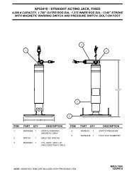
ADJUSTMENT NUT (5/16" OLD) - (1/2" NEW)<br />
ADJUSTMENT SCREW (Phillips or 1/4")<br />
(OLD STYLE)<br />
ADJUSTMENT NUT (7/8" or 3/4")<br />
B<br />
LED’S - LOCATION<br />
MAY BE DIFFERENT<br />
There are four LED’s on the Sensing Unit, A,B,C and D. Refer<br />
to the drawing below. The Sensing Unit is adjusted by turning<br />
the adjustment nut to turn out LED’s B and D. The adjustment<br />
screw will turn out LED’s A and C. If the adjustment nut has<br />
to be turned more than 1/2 flat or the adjustment screw has to<br />
be turned more than 3/4 turn to turn the LED out, there may<br />
be a problem with the Sensing Unit or the mounting of the<br />
Control Box. If two LED’s are on, it is best to make the B-D<br />
adjustments first, then hold the adjustment nut from moving<br />
while making the A-C adjustment.<br />
NOTE: If opposing LED’s are lit, there is a problem with<br />
the Sensing Unit.<br />
If LED (A) is lit: Turn the adjustment screw COUNTER<br />
CLOCKWISE until the LED is off.<br />
If LED (C) is lit: Turn the adjustment screw CLOCKWISE<br />
until the LED is off.<br />
If LED (B) is lit: Turn the adjustment nut COUNTER<br />
CLOCKWISE until the LED is off.<br />
A<br />
D<br />
C<br />
SENSING UNIT - TOP VIEW<br />
ADJUSTMENT<br />
NUT (5/16" OLD) - (1/2" NEW)<br />
ADJUSTMENT<br />
SCREW (Phillips or 1/4")<br />
CONTROL BOX - SIDE VIEW<br />
CONTROL<br />
BOX WALL<br />
(OLD STYLE)<br />
ADJUSTMENT<br />
NUT (7/8" or 3/4")<br />
If LED (D) is lit: Turn the adjustment nut CLOCKWISE<br />
until the LED is off.<br />
IMPORTANT: When all 4 LED’s are off, move the<br />
vehicle to an unlevel position so one or two yellow<br />
lights are on. Level the vehicle according to the yellow<br />
LEVEL lights. Recheck the level. If more adjustment is<br />
needed, DO NOT try to adjust the sensing unit until the<br />
yellow level lights go out, instead just "tweak" the<br />
sensing unit, ignoring the LED’s on the sensing unit.<br />
Example: After the initial adjustment and releveling<br />
the vehicle, the front is still low. This means the front<br />
yellow level light is turning off too soon. Determine<br />
which sensing unit light is the front light, A-B-C or D.<br />
Move the adjustment for that light very, very, slightly in<br />
the OPPOSITE direction that is given in the above<br />
instructions for LED’s A, B, C, and D. This will allow<br />
MP44.1501<br />
NOT IN PARK/BRAKE CHECK<br />
CAUTION: WHEN MAKING THIS CHECK, BLOCK<br />
THE COACH WHEELS SECURELY SO THE COACH<br />
CANNOT ROLL FORWARD OR BACKWARD.<br />
Set the park/brake. Switch the ignition to the "ACC" or "ON"<br />
position. Push the "ON/OFF" switch toward "ON". Release<br />
the parking brake and confirm that the "PARK" indicator light<br />
comes on. Reset the parking brake. The "PARK" indicator<br />
light should go out. Switch the ignition to "OFF".<br />
If any of the above checks or inspections reveal a problem<br />
or if there are other problems or questions, consult a<br />
qualified RV repair center, your vehicle or coach<br />
manufacturer, or <strong>HWH</strong> CORPORATION for service or repair.<br />
MP45.3259<br />
07MAY09
AIR LINE CONNECTION DIAGRAM<br />
FRONT AND DRIVE AXLE<br />
FRONT<br />
FRONT<br />
AXLE<br />
LINE FROM HEIGHT<br />
CONTROL VALVE<br />
LF AIR BAG<br />
PRESSURE<br />
SWITCH<br />
FRONT AIR<br />
MANIFOLD<br />
LINE FROM HEIGHT<br />
CONTROL VALVE<br />
RF AIR BAG<br />
PRESSURE<br />
SWITCH<br />
AIR BAG<br />
LINE TO<br />
AIR BAG<br />
LINE TO<br />
AIR BAG<br />
AIR SUPPLY<br />
COUNTRY<br />
COACH<br />
COMPRESSOR<br />
HCV<br />
HEIGHT<br />
CONTROL<br />
VALVE<br />
VEHICLE<br />
AIR SUPPLY<br />
FILTER<br />
N.O.<br />
<strong>HWH</strong> WATER TRAP<br />
IMPORTANT: MANIFOLDS ARE<br />
PRE-WIRED AND CONNECTIONS<br />
ARE LABELED. RIGHT AND LEFT<br />
CONNECTIONS MUST BE<br />
PROPERLY MAINTAINED.<br />
VEHICLE<br />
AIR SUPPLY<br />
DRIVE<br />
AXLE<br />
HCV<br />
LR AIR BAG<br />
PRESSURE<br />
SWITCH<br />
DRIVE<br />
AXLE<br />
MANIFOLD<br />
HCV<br />
RR AIR BAG<br />
PRESSURE<br />
SWITCH<br />
AIR BAG<br />
TO TAG MANIFOLD<br />
AIR SUPPLY<br />
SEE AIR LINE<br />
CONNECTION<br />
DIAGRAM<br />
TAG AXLE<br />
SEE AIR LINE<br />
CONNECTION<br />
DIAGRAM<br />
TAG AXLE<br />
TO TAG ENABLE<br />
CONNECTION<br />
SYSTEM<br />
AIR<br />
PRESSURE<br />
SWITCH<br />
SEE SPECIFIC MANIFOLD<br />
DIAGRAMS FOR CONNECTION<br />
INFORMATION<br />
MP75.010J<br />
09OCT01
AIR LINE CONNECTION DIAGRAM<br />
TAG AXLE<br />
SEE AIR LINE CONNECTION DIAGRAM<br />
FRONT AND DRIVE AXLE<br />
FRONT<br />
TAG<br />
AXLE<br />
FROM AIR<br />
SUPPLY<br />
LS TAG AIR<br />
BAG<br />
PRESSURE<br />
SWITCH 20 PSI<br />
AIR BAG<br />
AIR<br />
SUPPLY<br />
FROM DRIVE AXLE<br />
AIR BAGS<br />
TAG AXLE<br />
MANIFOLD<br />
RS TAG AIR<br />
BAG<br />
PRESSURE<br />
SWITCH 20 PSI<br />
LINES TO<br />
AIR BAGS<br />
TAG ENABLE<br />
CONNECTIONS<br />
AIR BAG<br />
TAG LIFT<br />
TO TAG<br />
LIFT<br />
TAG LIFT<br />
EXHAUST<br />
TAG LIFT<br />
PRESSURE<br />
REGULATOR<br />
BY FORETRAVEL<br />
100 PSI<br />
IMPORTANT: MANIFOLDS ARE PRE WIRED<br />
AND CONNECTIONS ARE LABELED. RIGHT<br />
AND LEFT CONNECTIONS MUST BE<br />
PROPERLY MAINTAINED<br />
SEE SPECIFIC MANIFOLD DIAGRAMS FOR<br />
CONNECTION INFORMATION<br />
VALVE REPLACEMENT NOTE: THE TAG DUMP/LOWER<br />
AIR SOLENOID VALVES ARE A DIFFERENT VALVE THAN<br />
THE OTHER VALVES ON THE MANIFOLD. ALL OTHER<br />
AIR SOLENOID VALVES ON THE FRONT, DRIVE AND<br />
TAG MANIFOLD ASSEMBLIES ARE THE SAME.<br />
MP75.110J<br />
03FEB03
AIR LEVEL SCHEMATIC<br />
4-POINT AIR LEVELING - FRONT AND DRIVE AXLE<br />
PRESSURE SWITCHES FRONT, REAR AND TAG<br />
HEIGHT<br />
CONTROL<br />
VALVE<br />
AIR SUPPLY<br />
AUXILIARY<br />
AIR COMPRESSOR<br />
(BY COUNTRY COACH)<br />
EXH<br />
FRONT MANIFOLD ASSEMBLY<br />
FILTER<br />
N.O.<br />
<strong>HWH</strong> WATER<br />
TRAP<br />
TRAVEL<br />
VALVE<br />
EXH<br />
LOWER<br />
VALVE<br />
TRAVEL<br />
VALVE<br />
EXH<br />
LOWER<br />
VALVE<br />
AIR BAG<br />
20 PSI PRESS<br />
SWITCH<br />
20 PSI PRESS<br />
SWITCH<br />
AIR BAG<br />
FRONT<br />
RAISE<br />
VALVE<br />
RAISE<br />
VALVE<br />
FRONT<br />
VEHICLE<br />
AIR<br />
SUPPLY<br />
HCV<br />
HCV<br />
VEHICLE<br />
AIR<br />
SUPPLY<br />
DRIVE AXLE MANIFOLD ASSEMBLY<br />
EXH<br />
EXH<br />
AIR BAG<br />
DRIVE<br />
AXLE<br />
TRAVEL<br />
VALVE<br />
EXH<br />
LOWER<br />
VALVE<br />
20 PSI PRESS<br />
SWITCH<br />
TRAVEL<br />
VALVE<br />
EXH<br />
LOWER<br />
VALVE<br />
20 PSI PRESS<br />
SWITCH<br />
AIR BAG<br />
DRIVE<br />
AXLE<br />
AIR BAG<br />
RAISE<br />
VALVE<br />
RAISE<br />
VALVE<br />
AIR BAG<br />
TO TAG<br />
ENABLE<br />
CONNECTION<br />
TAG AXLE<br />
AIR MANIFOLD<br />
AIR SUPPLY<br />
85 PSI<br />
PRESS SWITCH<br />
SEE AIR LEVEL SCHEMATIC<br />
4-POINT AIR LEVELING - TAG AXLE<br />
TO TAG<br />
ENABLE<br />
CONNECTION<br />
MP75.210J<br />
04APR02
AIR LEVEL SCHEMATIC<br />
4-POINT AIR LEVELING - TAG AXLE<br />
PRESSURE SWITCHES FRONT, REAR AND TAG<br />
AIR<br />
SUPPLY<br />
FROM DRIVE<br />
AXLE AIR BAG<br />
AIR LINE<br />
SEE AIR LEVEL SCHEMATIC<br />
4-POINT AIR LEVELING<br />
FRONT AND DRIVE AXLE<br />
TAG AXLE MANIFOLD ASSEMBLY<br />
FROM DRIVE AXLE<br />
AIR BAG AIR LINE<br />
TAG<br />
ENABLE<br />
VALVE<br />
TAG<br />
ENABLE<br />
VALVE<br />
AIR BAG<br />
20 PSI<br />
PRESS<br />
SWITCH<br />
20 PSI<br />
PRESS<br />
SWITCH<br />
AIR BAG<br />
TAG AXLE<br />
TAG<br />
DUMP<br />
VALVE<br />
TAG<br />
DUMP<br />
VALVE<br />
TAG AXLE<br />
EXH<br />
EXH<br />
TAG LIFT<br />
VALVE<br />
TAG LIFT<br />
EXHAUST VALVE<br />
EXH<br />
AIR SUPPLY<br />
TAG LIFT<br />
TAG LIFT<br />
MP75.310J<br />
04APR02
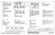
FRONT AIR SOLENOID MANIFOLD CONNECTIONS<br />
6 VALVE WITH TWO PRESSURE SWITCHES<br />
3.400"<br />
REAR<br />
VIEW<br />
LINES FROM HEIGHT<br />
CONTROL VALVES -<br />
TWO MAY BE TEE’D<br />
TOGETHER IF ONE<br />
HCV IS USED.<br />
EXHAUST<br />
PORT<br />
PRESSURE<br />
SWITCH-20 PSI<br />
LINE TO LF<br />
AIR BAG<br />
EXHAUST<br />
PORT<br />
PRESSURE<br />
SWITCH-20 PSI<br />
LINE TO RF<br />
AIR BAG<br />
LEFT SIDE<br />
IMPORTANT: LEFT AND RIGHT<br />
CONNECTIONS MUST BE MAINTAINED<br />
AS SHOWN. GROUND SUPPLY WIRES<br />
FOR AIR PRESSURE SWITCHES AND<br />
AIR SOLENOID VALVES CANNOT<br />
BE INTERCHANGED.<br />
RIGHT SIDE<br />
AIR<br />
SUPPLY<br />
A B<br />
RS<br />
TRAVEL<br />
B<br />
A<br />
RS<br />
PSW<br />
B<br />
A<br />
RS<br />
RAISE<br />
RS<br />
LOWER<br />
B A B<br />
A<br />
LS<br />
LOWER<br />
B<br />
A<br />
LS<br />
RAISE<br />
LS<br />
PSW<br />
B A B<br />
A<br />
LS<br />
TRAVEL<br />
B<br />
A<br />
SYS<br />
PSW<br />
B A B A B A B A B A B A B A B A<br />
MOUNTING HOLES<br />
RS<br />
TRAVEL<br />
RS<br />
PSW<br />
RS<br />
RAISE<br />
RS<br />
LOWER<br />
LS<br />
LOWER<br />
LS<br />
RAISE<br />
LS<br />
PSW<br />
LS<br />
TRAVEL<br />
LINE FROM HEIGHT<br />
CONTROL VALVE (MAY BE<br />
TEED TOGETHER IF ONE<br />
HCV IS USED)<br />
RIGHT SIDE<br />
VIEW<br />
EXHAUST PORTS<br />
(2 LEFT AND RIGHT)<br />
PRESSURE SWITCH<br />
20 PSI (2 LEFT AND RIGHT)<br />
LINE TO AIR BAGS<br />
(2 LEFT AND RIGHT)<br />
RIGHT TRAVEL<br />
SOLENOID VALVE (LEFT<br />
VALVE NOT SHOWN)<br />
RIGHT LOWER<br />
SOLENOID VALVE (LEFT<br />
VALVE NOT SHOWN)<br />
AIR SUPPLY<br />
NOTE: SOLENOID VALVES AND AIR<br />
LINE CONNECTIONS ARE<br />
LABELED.<br />
CHECK<br />
VALVE (2)<br />
RIGHT RAISE<br />
SOLENOID VALVE (LEFT<br />
VALVE NOT SHOWN)<br />
MP75.410J<br />
04APR02
REAR AIR SOLENOID MANIFOLD CONNECTIONS<br />
6 VALVE WITH THREE PRESSURE SWITCHES<br />
3.400"<br />
REAR<br />
VIEW<br />
LINES FROM HEIGHT<br />
CONTROL VALVES -<br />
TWO MAY BE TEE’D<br />
TOGETHER IF ONE<br />
HCV IS USED.<br />
NOTE: SOLENOID VALVES AND<br />
AIR LINE CONNECTIONS<br />
ARE LABELED.<br />
EXHAUST<br />
PORT<br />
PRESSURE<br />
SWITCH-20 PSI<br />
LINE TO LR<br />
AIR BAG<br />
EXHAUST<br />
PORT<br />
PRESSURE<br />
SWITCH-20 PSI<br />
LINE TO RR<br />
AIR BAG<br />
LEFT SIDE<br />
RIGHT SIDE<br />
PRESSURE<br />
SWITCH-85 PSI<br />
AIR<br />
SUPPLY<br />
RS<br />
TRAVEL<br />
RS<br />
PSW<br />
RS<br />
RAISE<br />
RS<br />
LOWER<br />
LS<br />
LOWER<br />
LS<br />
RAISE<br />
LS<br />
PSW<br />
LS<br />
TRAVEL<br />
SYS<br />
PSW<br />
IMPORTANT: LEFT AND RIGHT<br />
CONNECTIONS MUST BE MAINTAINED<br />
AS SHOWN. GROUND SUPPLY WIRES<br />
FOR AIR PRESSURE SWITCHES AND<br />
AIR SOLENOID VALVES CANNOT<br />
BE INTERCHANGED.<br />
A B<br />
B<br />
A<br />
B<br />
A<br />
B A B<br />
A<br />
B<br />
A<br />
B A B<br />
B A B A B A B A B A B A B A B A B A<br />
A<br />
B<br />
A<br />
MOUNTING HOLES<br />
RS<br />
TRAVEL<br />
RS<br />
PSW<br />
RS<br />
RAISE<br />
RS<br />
LOWER<br />
LS<br />
LOWER<br />
LS<br />
RAISE<br />
LS<br />
PSW<br />
LS<br />
TRAVEL<br />
SYS<br />
PSW<br />
LINE FROM HEIGHT<br />
CONTROL VALVE (MAY BE<br />
TEED TOGETHER IF ONE<br />
HCV IS USED)<br />
RIGHT SIDE<br />
VIEW<br />
EXHAUST PORTS<br />
(2 LEFT AND RIGHT)<br />
PRESSURE SWITCH<br />
20 PSI (2 LEFT AND RIGHT)<br />
LINE TO AIR BAGS<br />
(2 LEFT AND RIGHT)<br />
RIGHT TRAVEL<br />
SOLENOID VALVE (LEFT<br />
VALVE NOT SHOWN)<br />
RIGHT LOWER<br />
SOLENOID VALVE (LEFT<br />
VALVE NOT SHOWN)<br />
AIR SUPPLY<br />
PRESSURE<br />
SWITCH-85 PSI<br />
CHECK<br />
VALVE (2)<br />
RIGHT RAISE<br />
SOLENOID VALVE (LEFT<br />
VALVE NOT SHOWN)<br />
MP75.510J<br />
04APR02
TAG AIR SOLENOID MANIFOLD CONNECTIONS<br />
6 VALVE WITH TWO PRESSURE SWITCHES<br />
TO LS DRIVE<br />
AXLE<br />
AIR BAGS<br />
3.400"<br />
REAR<br />
VIEW<br />
MOUNTING HOLES<br />
TO RS DRIVE AXLE<br />
AIR BAGS<br />
NOTE:<br />
SOLENOID VALVES AND<br />
AIR LINE CONNECTIONS<br />
ARE LABELED.<br />
PRESSURE<br />
SWITCH-<br />
20 PSI<br />
PRESSURE<br />
SWITCH-20 PSI<br />
TO LS TAG<br />
AIR BAG<br />
LS TAG<br />
DUMP<br />
TO RS TAG<br />
AIR BAG<br />
RS TAG<br />
DUMP<br />
TO TAG<br />
LIFT<br />
TAG LIFT<br />
EXHAUST<br />
LEFT SIDE<br />
RIGHT SIDE<br />
NOTE: PRESSURE SWITCHES<br />
ON TAG AXLE MANIFOLD ARE<br />
NOT USED ON ALL SYSTEMS.<br />
AIR<br />
SUPPLY<br />
P.E.D<br />
RS TAG<br />
ENABLE<br />
P.E.D<br />
RS<br />
PSW<br />
P.E.D<br />
RS<br />
DUMP<br />
P.E.D<br />
TAG LIFT<br />
EXHAUST<br />
TAG<br />
LIFT<br />
P.E.D P.E.D<br />
LS<br />
DUMP<br />
P.E.D<br />
LS<br />
PSW<br />
P.E.D<br />
LS TAG<br />
ENABLE<br />
IMPORTANT: LEFT AND RIGHT CONNECTIONS<br />
MUST BE MAINTAINED AS SHOWN. GROUND<br />
SUPPLY WIRES FOR AIR PRESSURE SWITCHES<br />
AND AIR SOLENOID VALVES CANNOT BE<br />
INTERCHANGED.<br />
B A B A<br />
B<br />
A<br />
B<br />
A<br />
B<br />
A<br />
B<br />
A<br />
B<br />
A<br />
B<br />
A<br />
NOTE: THE TWO TAG DUMP SOLENOID<br />
VALVES ARE A DIFFERENT VALVE THEN THE<br />
OTHER FOUR VALVES ON THE MANIFOLD. MAKE<br />
SURE THE CORRECT VALVE IS OBTAINED<br />
FOR REPLACEMENT.<br />
RS TAG<br />
ENABLE<br />
RS<br />
PSW<br />
RS<br />
DUMP<br />
TAG LIFT<br />
EXHAUST<br />
TAG<br />
LIFT<br />
LS<br />
DUMP<br />
LS<br />
PSW<br />
LS TAG<br />
ENABLE<br />
RIGHT SIDE TAG ENABLE SOLENOID VALVE<br />
RIGHT<br />
SIDE<br />
VALVES<br />
LEFT<br />
SIDE<br />
VALVES<br />
LEFT SIDE TAG ENABLE SOLENOID VALVE<br />
RIGHT SIDE TAG DUMP SOLENOID VALVE<br />
LEFT SIDE TAG DUMP SOLENOID VALVE<br />
CHECK<br />
VALVE (1)<br />
TAG LIFT EXHAUST SOLENOID VALVE<br />
TAG LIFT SOLENOID VALVE<br />
MP75.610J<br />
04APR02
AIR LINE CONNECTION DIAGRAM<br />
WATER TRAP ASSEMBLY<br />
TOP VIEW<br />
AIR SUPPLY FROM<br />
AUXILIARY COMPRESSOR<br />
SUPPLIED BY<br />
COUNTRY COACH<br />
TO SUSPENSION<br />
FLOW<br />
CHECK VALVE<br />
SIDE VIEW<br />
SEE ELECTRICAL CONNECTION<br />
DIAGRAM - WATER TRAP<br />
ASSEMBLY FOR CONNECTION<br />
INFORMATION<br />
ADJUSTABLE<br />
RELIEF VALVE<br />
SET AT 130 PSI<br />
NORMALLY OPEN<br />
+12 VOLT SOLENOID<br />
VALVE<br />
MP75.710J<br />
05OCT01
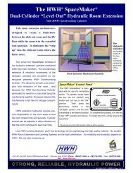
BREATHER CAP - DIPSTICK - 1/4" NUT DRIVER<br />
VALVE RELEASE<br />
NUT<br />
NOTE: DO NOT turn the valve<br />
release nut more than 4 and 1/2<br />
(four and one half) turns counter<br />
clockwise. Damage to the valve<br />
may result.<br />
1 1/2" DIAMETER<br />
SOLENOID VALVE<br />
PLASTIC PLUG<br />
REMOVE TO<br />
GAIN ACCESS<br />
TO THE 1/4"<br />
VALVE RELEASE<br />
NUT<br />
VALVE RELEASE<br />
NUT<br />
NOTE: DO NOT turn the valve<br />
release nut more than 2 full<br />
turns counter clockwise. Damage<br />
to the valve may result.<br />
2 1/4" DIAMETER<br />
SOLENOID VALVE<br />
NOTE: THE BREATHER CAP IS LOCATED<br />
ON THE TOP SIDE OF THE POWER UNIT RESERVOIR.<br />
1/4" NUT DRIVER<br />
OIL LEVEL<br />
OIL LEVEL GROOVES<br />
BREATHER CAP<br />
IMPORTANT: PRIOR TO REMOVING THE BREATHER CAP,<br />
EITHER TO CHECK THE OIL LEVEL OR TO USE THE 1/4" NUT DRIVER,<br />
CLEAN ANY DEBRIS FROM THE TOP OF THE RESERVOIR.<br />
BEFORE RETURNING THE BREATHER CAP TO THE RESERVOIR,<br />
REMOVE ANY PAINT CHIPS OR OTHER DEBRIS FROM THE DIPSTICK<br />
INCLUDING DEBRIS INSIDE THE 1/4" NUT DRIVER.<br />
MP85.999X<br />
20JAN10