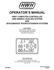
AIR SUSPENSIONS AND HWH - HWH Corporation
AIR SUSPENSIONS AND HWH - HWH Corporation
AIR SUSPENSIONS AND HWH - HWH Corporation
- No tags were found...

You also want an ePaper? Increase the reach of your titles
YUMPU automatically turns print PDFs into web optimized ePapers that Google loves.
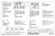
The following diagrams show detailed connections for several styles of manifolds.Figure 29 is a front air manifold with two 20 psi air bagpressure switches and a single air bag connection foreach side.Figure 30 is a drive axle manifold. It has two 20 psi airbag pressure switches and an 85 psi system pressureswitch. This manifold has connections for two air bagson each side.Figure 31 is a tag axle manifold. It has two 20 psi airbag pressure switches. This manifold has no heightcontrol valve connections but is connected to the left andright side drive axle air bags. The drive axle heightcontrol valves control the tag axle air bags. There is asingle air bag connection on each side and a connectionfor the tag lift mechanism.3-4 System wiring. The system wiring, like the plumbing can vary between manufacturers and vehicles.With the older 500 and 600 series leveling systems, the wiring was very consistent and only changed if atag axle lift was incorporated into the system. Even vehicles with a tag axle were not complicated. Whentraveling or leveling, the tag and drive axles were controlled as one axle. If a tag lift was used, relays in thecontrol box isolated the tag from the drive axle so the tag axle air bags could be dumped and the tag lifted.The basic, single control box 2000 series CAN air leveling system is wired much like a 500 or 600 seriessystem. The two main differences are the CAN system has the ability to recognize a signal from thetransmission speed switch for the “Dump” and “Raise” functions and the CAN control box uses four powerinputs instead of the three that the 500 and 600 systems used. Electrical information for specific systemswill be discussed in greater detail in Lesson 14 of the <strong>HWH</strong> Online Technical school.It is important to get specific wiring diagrams and/or system schematics when addressing wiringissues. Repair manuals are available for the 500 series, 600 series and the single control box 2000series CAN leveling systems. These manuals contain basic wiring diagrams for these systems.Page 21 – 22JUL09