-DIN DIGITAL INDICATOR Product Manual - Instrumentation Central
-DIN DIGITAL INDICATOR Product Manual - Instrumentation Central
-DIN DIGITAL INDICATOR Product Manual - Instrumentation Central

You also want an ePaper? Increase the reach of your titles
YUMPU automatically turns print PDFs into web optimized ePapers that Google loves.
1<br />
-<strong>DIN</strong><br />
1 6<br />
<strong>DIGITAL</strong> <strong>INDICATOR</strong><br />
<strong>Product</strong> <strong>Manual</strong>
How to use this manual
PM-0092<br />
1<br />
-<strong>DIN</strong> 16<br />
<strong>DIGITAL</strong> <strong>INDICATOR</strong><br />
PRODUCT MANUAL<br />
VOLUME I<br />
OPERATING INSTRUCTIONS<br />
In normal operation, the operator must not remove the Indicator<br />
from its housing or have unrestricted access to the rear terminals, as<br />
this would provide potential contact with hazardous live parts.<br />
Installation and configuration must be undertaken by<br />
technically-competent servicing personnel. This is covered in<br />
Volume II of this manual.<br />
Contents<br />
1 OPERATOR MODE 1-1<br />
1.1 INTRODUCTION 1-1<br />
1.2 AVAILABLE DISPLAYS 1-1<br />
1.3 OVER-RANGE/UNDER-RANGE DISPLAYS ` 1-2<br />
1.4 SENSOR BREAK INDICATION 1-2<br />
1.5 VIEWING THE HARDWARE DEFINITION CODE 1-2<br />
2 SET UP MODE 2-1<br />
2.1 ENTRY INTO SET UP MODE 2-1<br />
2.1.1 Remote Lock Option Not Fitted<br />
or Fitted and Set OFF 2-1<br />
2.1.2 Remote Lock Option Fitted and Set ON 2-1<br />
2.1.3 All Set Up Parameters at Default Values 2-1<br />
2.2 SET UP MODE PARAMETERS 2-2<br />
O0092-FM Volume I (iii)
PM-0092<br />
2.2.1 Alarm 1 Value 2-3<br />
2.2.2 Alarm 2 Value 2-3<br />
2.2.3 Linear Input Scale Range Maximum 2-3<br />
2.2.4 Linear Input Scale Range Minimum 2-4<br />
2.2.5 Recorder Output Scale Maximum 2-4<br />
2.2.6 Recorder Output Scale Minimum 2-4<br />
2.3 EXIT FROM SET UP MODE 2-4<br />
2.3.1 Remote Lock Option Not Fitted<br />
or Fitted and Set OFF 2-4<br />
2.3.2 Remote Lock Option Fitted and Set ON 2-5<br />
(iv) Volume I O0092-FM
PM-0092<br />
1 OPERATOR MODE<br />
1.1 INTRODUCTION<br />
The Operator Mode is the normal mode of the Indicator. The front panel displays,<br />
indicators and keys are shown below.<br />
1.2 AVAILABLE DISPLAYS<br />
For descriptions of the various types of alarm available, see Figure 2-2.<br />
O092-1 Volume I 1-1
PM-0092<br />
1.3 OVER-RANGE/UNDER-RANGE DISPLAYS<br />
If the process variable attains a value higher than the input scale maximum limit<br />
(over-range) or lower than the input scale minimum limit (under-range), the<br />
four-digit display will show the appropriate one of the following:<br />
1.4 SENSOR BREAK INDICATION<br />
If a break is detected in the sensor circuit, the four-digit display will show:<br />
The reaction of the alarms to a sensor break is dependent upon the input type.<br />
1.5 VIEWING THE HARDWARE DEFINITION CODE<br />
To view the current Hardware Definition Code setting (indicating input/output<br />
types) and Hardware Option setting (indicating the option(s) fitted):<br />
1 -2 Volume I O092-1
PM-0092<br />
2 SET UP MODE<br />
2.1 ENTRY INTO SET UP MODE<br />
2.1.1 Remote Lock Option Not Fitted or Fitted and Set OFF<br />
2.1.2 Remote Lock Option Fitted and Set ON<br />
It is not possible to enter into/exit from Set Up Mode via the front panel. Access to<br />
this mode is controlled by the Remote Lock Option. The “no key activity”<br />
automatic return to Operator Mode is inoperative.<br />
2.1.3 All Set Up Parameters at Default Values<br />
If the four-digit display shows:<br />
(i.e. all decimal point positions illuminated), this indicates that one or more of the<br />
critical configuration parameters - typically input range - have been altered in<br />
value/setting and, as a consequence, all Set Up Mode parameters have been<br />
automatically set to their default values/settings. To clear this display, simply alter<br />
the value/setting of any Set Up Mode parameter (see below). It is recommended<br />
that all configuration parameters be set as required before any adjustment is<br />
made to the Set Up Mode parameters.<br />
O092-2 Volume I 2-1
PM-0092<br />
2.2 SET UP MODE PARAMETERS<br />
The parameters available for view/adjustment in Set Up Mode are summarised in<br />
Table 2-1. The parameter sequence is shown in Figure 2-1.<br />
Figure 2-1<br />
Set Up Mode Parameter Sequence<br />
2-2 Volume I O092-2
PM-0092<br />
Parameter Adjustment Range Default<br />
Alarm 1 value Range Min. To Range Max. Range Max. (Process High)<br />
Range Min. (Process Low)<br />
Alarm 2 value 1 Range Min. To Range Max. Range Max. (Process High)<br />
Range Min. (Process Low)<br />
Linear Input Decimal<br />
Point Position 2<br />
Table 2-1<br />
2.2.1 Alarm 1 Value<br />
If Alarm 1 is selected to be a Process High alarm, this defines the process variable<br />
value at or above which Alarm 1 will be active. If Alarm 1 is selected to be a<br />
Process Low alarm, this defines the process variable value at or below which<br />
Alarm 1 will be active. Alarm operation is illustrated in Figure 2-2.<br />
2.2.2 Alarm 2 Value<br />
Set Up Mode Parameters<br />
0 (XXXX), 1 (XXX.X),<br />
2 (XX.XX) or 3 (X.XXX)<br />
If Alarm 2 is selected to be a Process High alarm, this defines the process variable<br />
value at or above which Alarm 2 will be active. If Alarm 2 is selected to be a<br />
Process Low alarm, this defines the process variable value at or below which<br />
Alarm 2 will be active. Alarm operation is illustrated in Figure 2-2.<br />
2.2.3 Linear Input Scale Range Maximum<br />
1 (XXX.X)<br />
Linear Input Scale −1999 to 9999 1000<br />
Range Maximum 2<br />
Linear Input Scale −1999 to 9999 0000<br />
Range Minimum 2<br />
Recorder Outout −1999 to 9999 Range Max.<br />
Scale Maximum 3<br />
Recorder Output −1999 to 9999 Range Min.<br />
Scale Minimum 3<br />
NOTES<br />
1. Appears only if Alarm 2 is fitted/configured.<br />
2. Applicable only if a DC Linear input is fitted.<br />
3. Applicable only if the Recorder Output option is fitted.<br />
This parameter defines the scaled input value when the process variable input is<br />
at its maximum value. The decimal point position as defined by Linear Input<br />
Decimal Point Position. This parameter can be set to a value less than (but not<br />
equal to) Linear Input Scale Range Minimum, in which case the sense of the input<br />
is reversed.<br />
O092-2 Volume I 2-3
PM-0092<br />
2.2.4 Linear Input Scale Range Minimum<br />
This parameter defines the scaled input value when the process variable input is<br />
at its minimum value. The decimal point positon as defined by Linear Input<br />
Decimal Point Position). This parameter can be set to a value greater than (but not<br />
equal to) Linear Input Scale Range Maximum, in which case the sense of the input<br />
is reversed.<br />
2.2.5 Recorder Output Scale Maximum<br />
This parameter defines the value of process variable at which the Recorder<br />
Output reaches its maximum value; for example, for a 0 - 5V Recorder Output, this<br />
value corresponds to 5V. The decimal point position for the Recorder Output is<br />
always the same as that for the process variable input range.<br />
NOTE: If this parameter is set to a value less than that for the Recorder<br />
Output Scale Minimum (see Subsection 2.2.6), the relationship between the<br />
process variable/setpoint value and the Recorder Output is reversed.<br />
2.2.6 Recorder Output Scale Minimum<br />
This parameter defines the value of the process variable at which the Recorder<br />
Output reaches its minimum value; for example, for a 0 - 5V Recorder Output, this<br />
value corresponds to 0V. The decimal point position for the Recorder Output is<br />
always the same as that for the process variable input range.<br />
NOTE: If this parameter is set to a value greater than that for the Recorder<br />
Output Scale Maximum (see Subsection 2.2.5), the relationship between the<br />
process variable value and the Recorder Output is reversed.<br />
2.3 EXIT FROM SET UP MODE<br />
2.3.1 Remote Lock Option Not Fitted or Fitted and Set OFF<br />
2-4 Volume I O092-2
PM-0092<br />
2.3.2 Remote Lock Option Fitted and Set ON<br />
It is not possible to exit from Set Up Mode from the front panel. Exit from this mode<br />
is controlled by the Remote Lock Option.<br />
Figure 2-2<br />
Alarm Operation<br />
O092-2 Volume I 2-5
PM-0092<br />
1<br />
16-<strong>DIN</strong> <strong>DIGITAL</strong> <strong>INDICATOR</strong><br />
PRODUCT MANUAL<br />
VOLUME II<br />
INSTALLATION & CONFIGURATION<br />
INSTRUCTIONS<br />
The procedures described in this Volume must be undertaken only by<br />
technically-competent servicing personnel.<br />
Contents<br />
1 INSTALLATION 1-1<br />
1.1 UNPACKING PROCEDURE 1-1<br />
1.2 PANEL-MOUNTING 1-1<br />
1.3 CONNECTIONS AND WIRING 1-3<br />
1.3.1 Mains (Line) Input 1-4<br />
1.3.2 24V (Nominal) AC/DC Supply 1-4<br />
1.3.3 Thermocouple Input 1-4<br />
1.3.4 RTD Input 1-4<br />
1.3.5 Linear Input 1-5<br />
1.3.6 Set Up Mode Remote Lock (Option) 1-5<br />
1.3.7 Relay Outputs 1-5<br />
1.3.8 DC Output (Recorder Output) 1-5<br />
2 INTERNAL LINKS AND SWITCHES 2-1<br />
2.1 REMOVING THE INSTRUMENT FROM ITS HOUSING 2-1<br />
2.2 REMOVING/REPLACING THE ALARM 2/RECORDER OUTPUT<br />
OPTION PCBs 2-3<br />
S092-FM Volume II (i)
PM-0092<br />
2.3 REMOVING/REPLACING THE SET UP MODE REMOTE<br />
LOCK OPTION PCB 2-3<br />
2.4 REPLACING THE INSTRUMENT IN ITS HOUSING 2-4<br />
2.5 SELECTION OF INPUT TYPE 2-4<br />
2.6 ALARM 2 OUTPUT TYPE 2-5<br />
2.7 RECORDER OUTPUT RANGE SELECTION 2-5<br />
3 CONFIGURATION MODE 3-1<br />
3.1 ENTRY INTO CONFIGURATION MODE 3-1<br />
3.2 HARDWARE DEFINITION CODE 3-2<br />
3.3 HARDWARE OPTION 3-3<br />
3.4 INPUT RANGE 3-4<br />
3.5 ALARM TYPE 3-4<br />
3.6 EXIT FROM CONFIGURATION MODE 3-4<br />
APPENDIX A PRODUCT SPECIFICATION A-1<br />
(ii) Volume II S092-FM
PM-0092<br />
1 INSTALLATION<br />
1.1 UNPACKING PROCEDURE<br />
1. Remove the instrument from its packing. The instrument is supplied with a<br />
panel gasket and push-fit fixing strap. Retain the packing for future use,<br />
should it be necessary to transport the instrument to a different site or to<br />
return it to the supplier for repair/testing.<br />
2. Examine the delivered items for damage or deficiencies. If any is found,<br />
notify the carrier immediately.<br />
1.2 PANEL-MOUNTING<br />
The panel on which the instrument<br />
is to be mounted must be rigid<br />
and may be up to 6.0mm (0.25<br />
inches) thick. The cut-out required<br />
for a single Digital Indicator is as<br />
shown in Figure 1-1.<br />
The Digital Indicator is 110mm<br />
deep (measured from the rear<br />
face of the front panel). The front<br />
panel is 48mm high and 48mm<br />
wide. When panel-mounted, the<br />
front panel projects 10mm from<br />
the mounting panel. The main<br />
dimensions of the instrument are<br />
shown in Figure 1-2.<br />
Figure 1-1<br />
Panel Cut-out Dimensions<br />
Figure 1-2<br />
Main Dimensions<br />
S0092-1 Volume II 1-1
PM-0092<br />
To panel-mount the instrument:<br />
1. Insert the rear of the housing through the cut-out (from the front of the<br />
mounting panel) and hold the instrument lightly in position against the<br />
panel. Ensure that the panel gasket is not distorted and that the instrument<br />
is positioned squarely against the mounting panel. Apply pressure to the<br />
front panel bezel only.<br />
CAUTION: Do not remove the panel gasket, as this may result in<br />
inadequate clamping of the instrument in the panel.<br />
2. Slide the fixing strap in place (see Figure 1-3) and push it forward until it is<br />
firmly in contact with the rear face of the mounting panel (the tongues on<br />
the strap should have engaged in matching rachet positions on the<br />
housing and the fixing strap springs should be pushing firmly against the<br />
mounting panel rear face).<br />
Once the instrument is installed in its mounting panel, it may be subsequently<br />
removed from its housing, if necessary, as described in Subsection 2.1.<br />
Figure 1-3<br />
Panel-Mounting Procedure<br />
1 -2 Volume II S0092-1
PM-0092<br />
1.3 CONNECTIONS AND WIRING<br />
The rear terminal connections are illustrated in Figure 1-4.<br />
Figure 1-4<br />
Rear Terminal Connections<br />
S0092-1 Volume II 1-3
PM-0092<br />
1.3.1 Mains (Line) Input<br />
The instrument will operate on 96 - 264V AC 50/60Hz mains (line) supply. The power<br />
consumption is approximately 4 VA.<br />
CAUTION: This equipment is designed for installation in an enclosure<br />
which provides adequate protection against electric shock. Local<br />
regulations regarding electrical installation should be rigidly<br />
observed. Consideration should be given to prevention of access to<br />
the power terminations by unauthorised personnel. Power should be<br />
connected via a two-pole isolating switch (preferably situated near<br />
the equipment) and a 1A fuse, as shown in Figure 1-4.<br />
If the instrument has relay outputs in which the contacts are to carry<br />
mains (line) voltage, it is recommended that the relay contact mains<br />
(line) supply should be switched and fused in a similar manner but<br />
should be separate from the instrument mains (line) supply.<br />
1.3.2 24V (Nominal) AC/DC Supply<br />
The supply connections for the 24V AC/DC version are shown in Figure 1-4. Power<br />
should be connected via a two-pole isolating switch and a 315mA slow-blow fuse<br />
(anti-surge Type T).<br />
The nominal 24V supply may be in the following ranges:<br />
24V (nominal) AC 50/60Hz -<br />
24V (nominal) DC -<br />
20 - 50V<br />
22 - 65V<br />
1.3.3 Thermocouple Input<br />
The correct type of thermocouple extension leadwire/compensating cable must<br />
be used for the entire distance between the instrument and the thermocouple,<br />
ensuring that correct polarity is observed throughout. Joints in the cable should be<br />
avoided, if possible.<br />
NOTE: Do not run thermocouple cables adjacent to power-carrying<br />
conductors. If the wiring is run in a conduit, use a separate conduit for the<br />
thermocouple wiring. If the thermocouple is grounded, this must be done at<br />
one point only. If the thermocouple extension lead is shielded, the shield<br />
must be grounded at one point only.<br />
1.3.4 RTD Input<br />
The compensating lead should be connected to Terminal 4. For two-wire RTD<br />
inputs, Terminals 4 and 5 should be linked. The extension leads should be of<br />
copper and the resistance of the wires connecting the resistance element should<br />
not exceed 5 ohms per lead (the leads should be of equal length).<br />
1-4 Volume II S0092-1
PM-0092<br />
1.3.5 Linear Input<br />
For linear mA input ranges, connection is made to Terminals 4 and 6 in the<br />
polarity shown in Figure 1-4. For linear mV and V ranges, connection is made to<br />
Terminals 4 and 5 in the polarity shown in Figure 1-4. For details of the linear input<br />
ranges available, refer to Appendix A.<br />
1.3.6 Set Up Mode Remote Lock (Option)<br />
With this option fitted and configured, Terminals 11 and 12 may be connected to<br />
(a) the voltage-free contacts of a switch or relay, or (b) a TTL-compatible voltage.<br />
Set Up Mode entry/exit is initiated as follows:<br />
Voltage-Free:<br />
TTL-compatible:<br />
Contacts open - out of Set Up Mode<br />
Contacts closed - in Set Up Mode<br />
>2.0V - out of Set Up Mode<br />
PM-0092<br />
2 INTERNAL LINKS AND SWITCHES<br />
2.1 REMOVING THE INSTRUMENT FROM ITS HOUSING<br />
CAUTION: Before removing the instrument from its housing, ensure<br />
that all power has been removed from the rear terminals.<br />
To withdraw the instrument from its housing, simply grip the side edges of the front<br />
panel (there is a finger grip on each edge) and pull the instrument forwards. This<br />
will release the instrument from its rear connectors in the housing and will give<br />
access to the PCBs. Take note of the orientation of the instrument for subsequent<br />
replacement into the housing.The positions of the PCBs in the instrument are shown<br />
in Figure 2-1.<br />
Figure 2-1<br />
PCB Positions<br />
2 -1 Volume II S0092-2
PM-0092<br />
Figure 2-2<br />
Removing the Alarm 2 Output/Recorder Output Option PCB<br />
S0092-2 Volume II 2-2
PM-0092<br />
2.2 REMOVING/REPLACING THE ALARM 2/RECORDER<br />
OUTPUT OPTION PCBs<br />
With the instrument removed from its housing:<br />
1. Gently push the rear ends of the CPU PCB and Power Supply PCB apart<br />
slightly, until the two tongues on each of the Option PCBs become<br />
dis-engaged - see Figure 2-2B; The Alarm 2 Option PCB tongues engage in<br />
holes in the Power Supply PCB and the Recorder Output Option PCB<br />
tongues engage in holes on the CPU PCB.<br />
2. Carefully pull the required Option PCB (Alarm 2 or Recorder Output) from<br />
its connector (Alarm 2 Option PCB is connected to the CPU PCB and<br />
Recorder Output Option PCB is connected to the Power Supply PCB) - see<br />
Figure 2-2C. Note the orientation of the PCB in preparation for its<br />
replacement.<br />
Adjustments may now be made to the link jumpers on the CPU PCB. The<br />
replacement procedure is a simple reversal of the removal procedure.<br />
2.3 REMOVING/REPLACING THE SET UP MODE REMOTE<br />
LOCK OPTION PCB<br />
The Set Up Mode Remote Lock Option PCB is mounted on the inner surface of the<br />
Power Supply PCB and can be removed when the instrument is removed from its<br />
housing (see Subsection 2.1). Figure 2-3 illustrates the removal/replacement<br />
procedure. It is not necessary to remove the Alarm 2/Recorder Output Option<br />
PCBs to perform this procedure.<br />
Figure 2-3<br />
Removing/Replacing the Set Up Mode Remote Lock Option PCB<br />
2-3 Volume II S0092-2
PM-0092<br />
2.4 REPLACING THE INSTRUMENT IN ITS HOUSING<br />
To replace the instrument, simply align the CPU PCB and Power Supply PCB with<br />
their guides and connectors in the housing and slowly but firmly push the<br />
instrument into position.<br />
CAUTION: Ensure that the instrument is correctly orientated. A stop will<br />
operate if an attempt is made to insert the instrument in the wrong<br />
orientation (e.g. upside-down). This stop must not be over-ridden.<br />
2.5 SELECTION OF INPUT TYPE<br />
The required input type is selected on link jumpers LJ1/LJ2/LJ3 on the CPU PCB (see<br />
Figure 2-4 and Table 2-1).<br />
Figure 2-4<br />
CPU PCB Link Jumpers<br />
Table 2-1<br />
Input Type<br />
RTD or DC (mV)<br />
Thermocouple<br />
DC (mA)<br />
DC (V)<br />
Input Type Selection<br />
CPU PCB Link Jumper Fitted<br />
None (parked)<br />
LJ3<br />
LJ2<br />
LJ1<br />
S0092-2 Volume II 2-4
PM-0092<br />
2.6 ALARM 2 OUTPUT TYPE<br />
Alarm 2 Output is always a relay type.<br />
2.7 RECORDER OUTPUT RANGE SELECTION<br />
The Recorder Output is a DC output, the range of which is determined by the<br />
setting of Link Jumpers LJ8 and LJ9 on the Recorder Output Option PCB (see Figure<br />
2-5 and Table 2-2).<br />
Table 2-2<br />
Recorder Output<br />
Range Selection<br />
Output Range Link Jumper Fitted<br />
0 - 10V LJ8<br />
0 - 20mA LJ9<br />
0 - 5V LJ8<br />
4 - 20mA LJ9<br />
Figure 2-5<br />
Recorder Output Option PCB<br />
2-5 Volume II S0092-2
PM-0092<br />
3 CONFIGURATION MODE<br />
3.1 ENTRY INTO CONFIGURATION MODE<br />
If this is done whilst the instrument is displaying the process variable value, the<br />
instrument will enter/exit Set Up Mode - keep holding the keys down!<br />
NOTE: This need not be the first key action after power-up.<br />
The user is then presented with the first of a sequence of parameter displays; in<br />
each instance, the parameter is be identified by the state of the SET1 and SET2<br />
indicators and the setting of that parameter is shown in the four-digit display. The<br />
user may then step through the parameters using the Scroll key. The setting may<br />
be adjusted using the Raise/Lower keys. As soon as the value/setting is changed,<br />
the four-digit display will flash, indicating that the new value/setting has yet to be<br />
confirmed (this flashing is inhibited during actual adjustment). When the<br />
value/setting is as required, it may be confirmed by:<br />
(a) pressing the Scroll key, whereupon the four-digit display will show:<br />
(b) pressing the Raise key.<br />
S0092-3 Volume II 3-1
PM-0092<br />
The four-digit display will then show a static (non-flashing) display of the new<br />
parameter setting. Depression of any key other than the Raise key at the SurE<br />
display will cause the original parameter setting to be retained. The sequence of<br />
parameter displays is shown below.<br />
NOTE: Changes to the value/setting of certain Configuration Mode<br />
parameters (e.g. input range, output use and type) will cause the Set Up<br />
Mode parameters to be automatically set to their default values (see also<br />
Volume 1, start of Section 2). It is recommended that all Configuration<br />
Mode parameters are finalised before Set Up Mode parameters are<br />
adjusted.<br />
Parameter Indicators ON Available ettings Default<br />
Input<br />
Range<br />
Alarm 1<br />
Type<br />
SET 1 & SET 2 Defined by input code (see Appendix A) 1419<br />
SET 1 only<br />
Process High, direct-acting<br />
Process High, reverse-acting<br />
Process Low, direct-acting<br />
Process Low, reverse-acting<br />
Alarm 2<br />
Type<br />
SET 2 only<br />
Not in use<br />
Process High, direct-acting<br />
Process High, reverse-acting<br />
Process Low, direct-acting<br />
Process Low, reverse-acting<br />
3.2 HARDWARE DEFINITION CODE<br />
This parameter is used to represent the hardware fitted (input type, Alarm 2 output<br />
fitted/not fitted, Recorder Output fitted/not fitted and Recorder Output range); this<br />
must be compatible with the hardware actually fitted. The Hardware Definition<br />
Code is accessed by pressing the Scroll and Lower keys simultaneously whilst the<br />
instrument is in Configuration Mode, whereupon the indicator adjacent to the<br />
Scroll key will flash at double rate and SET1 will come ON. The code is used as<br />
follows:<br />
3-2 Volume II S0092-3
PM-0092<br />
This code is may be adjusted as described previously. The maximum setting<br />
available for this code is 4117. For example, the code for an instrument with a<br />
thermocouple input, Alarm 1 Output, Alarm 2 Output and no Recorder Output<br />
would be 2110.<br />
NOTE: It is essential that this code is changed promptly whenever there is a<br />
change to the instrument’s hardware configuration (change of input/output<br />
type, alarm/recorder output added/removed etc.). The instrument software<br />
depends upon this code to ensure correct operation.<br />
To return to Configuration Mode, press the Scroll and Lower keys simultaneously.<br />
This code may also be viewed as a Read Only display in Operator Mode (see<br />
Volume 1, Subsection 1.5).<br />
3.3 HARDWARE OPTION<br />
There is one hardware option available - Set Up Mode Remote Lock. Access is<br />
gained to the Hardware Option parameter by pressing the Scroll key whilst the<br />
Hardware Definition Code is displayed in Configuration Mode, whereupon the<br />
indicator adjacent to the Scroll key will continue to flash at double rate, SET1 will<br />
be OFF and SET2 will be ON.<br />
The Set Up Mode Remote Lock option may be set to either of two settings:<br />
The desired setting is selected via the Raise/Lower keys.<br />
S0092-3 Volume II 3-3
PM-0092<br />
NOTE: With Remote Lock on, Set Up Mode cannot be accessed/exited from<br />
the front panel; with Remote Lock off, entry/exit is via the front panel keys<br />
and the external contacts/signal will have no effect.<br />
To return to the Hardware Definition Code display, press the Scroll key.<br />
The Hardware Option display may be viewed as a Read Only display in Operator<br />
Mode (see Volume 1, Subsection 1.5).<br />
3.4 INPUT RANGE<br />
The default setting of this parameter is dependent upon the input hardware fitted,<br />
as indicated by the first (left-most) digit of the Hardware Definition Code (see<br />
Subsection 3.2):<br />
Input Hardware Fitted<br />
Thermocouple<br />
RTD/Linear (mV)<br />
Linear (mA)<br />
If the Hardware Definition Code is at its default setting, input code 1419 will be<br />
displayed. The input ranges and codes available are listed in Appendix A.<br />
3.5 ALARM TYPE<br />
Default Setting<br />
1419 (Type “J”, 0 to 761°C)<br />
7220 (RTD Pt100, 0 to 800°C)<br />
3414 (4 to 20mA)<br />
Linear (V) 4446 (0 to 10V)<br />
The operation of the different alarm types is shown in Volume 1, Figure 2-2.<br />
3.6 EXIT FROM CONFIGURATION MODE<br />
NOTE: An automatic return to Operator<br />
Mode is made if, in Configuration Mode,<br />
there is no front panel key activity for five<br />
minutes.<br />
The exit is made via the power-up self-test<br />
routines which include an LED indicator test.<br />
3-4 Volume II S0092-3
PM-0092<br />
APPENDIX A<br />
PRODUCT SPECIFICATION<br />
UNIVERSAL INPUT<br />
General<br />
Maximum per Instrument:<br />
Input Sample Rate:<br />
One<br />
Four samples/second<br />
Digital Input Filter: Time constant selectable from front panel -<br />
0.0 (i.e. OFF), 0.5 to 100.0 seconds in<br />
0.5-second increments.<br />
Input Resolution:<br />
Input Impedance:<br />
Isolation:<br />
14 bits approximately; always four times<br />
better than display resolution.<br />
Greater than 100M Ω resistive (except for<br />
DC mA and V inputs).<br />
Universal input isolated from all outputs<br />
except SSR Drive at 240V AC.<br />
Thermocouple<br />
Ranges selectable from front panel:<br />
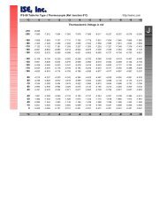
Type Input Range Dislayed Code Type Input Range Displayed Code<br />
R 0 - 1650°C 1127 J 32 - 1401°F 1420<br />
R 32 - 3002°F 1128 T -200 - 262 °C 1525<br />
S 0 - 1649°C 1227 T -328 - 503 °F 1526<br />
S 32 - 3000°F 1228 T 0.0 - 260.6°C 1541<br />
J 0.0 - 205.4°C 1415 T 32.0 - 501.0°F 1542<br />
J 32.0 - 401.7°F 1416 K -200 - 760°C 6726<br />
J 0 - 450 °C 1417 K -328 - 1399 °F 6727<br />
J 32 - 842°F 1418 K -200 - 1373 °C 6709<br />
J 0 - 761 °C * 1419 K -328 - 2503 °F 6710<br />
* Default setting<br />
Continued overleaf⇒<br />
S0092-A Volume II A-1
PM-0092<br />
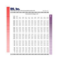
Type Input Range Dislayed Code Type Input Range Displayed Code<br />
L 0.0 - 205.7°C 1815 L 32 - 1403°F 1820<br />
L 32.0 - 402.2°F 1816 B 211 - 3315°F 1934<br />
L 0 - 450°C 1817 B 100 - 1824°C 1938<br />
L 32 - 841°F 1818 N 0 - 1399°C 5371<br />
L 0 - 762°C 1819 N 32 - 2550°F 5324<br />
Calibration:<br />
Sensor Break Protection:<br />
Complies with BS4937, NBS125 and IEC584.<br />
Break detected within two seconds. Alarms<br />
operate as if the process variable has<br />
gone over-range.<br />
Resistance Temperature Detector (RTD) and DC mV<br />
Ranges selectable from front panel:<br />
Input Range Displayed Code Input Range Displayed Code<br />
0 - 800°C * 7220 0.0 - 100.9°C 2295<br />
32 - 1471°F 7221 32.0 - 213.6°F 2296<br />
32 - 571°F 2229 -200 - 206°C 2297<br />
-100.9 - 100.0°C 2230 -328 - 402°F 2298<br />
-149.7 - 211.9°F 2231 -100.9 - 537.3°C 7222<br />
0 - 300 °C 2251 -149.7 - 999.1°F 7223<br />
* Default setting<br />
Type and Connection:<br />
Calibration:<br />
Lead Compensation:<br />
RTD Sensor Current:<br />
Sensor Break Protection:<br />
Three-wire Pt100<br />
Complies with BS1904 and <strong>DIN</strong>43760.<br />
Automatic scheme.<br />
150µA (approximately)<br />
Break detected within two seconds. For RTD<br />
input, alarms operate as if the process<br />
variable has gone under-range. For DC<br />
(mV) input, alarms operate as if the process<br />
variable has gone over-range.<br />
A-2 Volume II S0092-A
PM-0092<br />
DC Linear<br />
Ranges Selectable from Front Panel:<br />
Input Range Displayed Code Input Range Displayed Code<br />
0 - 20mA 3413 0 - 5V 4445<br />
4 - 20mA * 3414 1 - 5V 4434<br />
0 - 50mV 4443 0 - 10V * 4446<br />
10 - 50mV 4499 2 - 10V 4450<br />
* Default setting<br />
(Changes may also be required to the CPU PCB link jumpers - see Subsection<br />
2.5.)<br />
Scale Range Maximum:<br />
Scale Range Minimum:<br />
Minimum Span:<br />
Sensor Break Protection:<br />
–1999 to 9999. Decimal point as required.<br />
–1999 to 9999. Decimal point as for Scale<br />
Range Maximum.<br />
1 display LSD.<br />
Applicable to 4 - 20mA, 1 - 5V and 2 - 10V<br />
ranges only. Break detected within two<br />
seconds. Alarms operate as if the process<br />
variable has gone under-range.<br />
REMOTE LOCK INPUT (option)<br />
Type:<br />
Voltage-Free Operation:<br />
Voltage-free or TTL-compatible<br />
Connection to contacts of external switch<br />
or relay; contacts open = exit Set Up Mode<br />
(minimum contact resistance = 5000Ω),<br />
contacts closed = enter Set Up Mode<br />
(maximum contact resistance = 50Ω).<br />
TTL levels: To exit Set Up Mode: –0.6V to 0.8V<br />
To enter Set Up Mode 2: 2.0V to 24V<br />
Maximum Input Delay<br />
(OFF-ON):<br />
Minimum Input Delay<br />
(ON-OFF):<br />
1 second<br />
1 second<br />
S0092-A Volume II A-3
PM-0092<br />
OUTPUT 1 (Relay)<br />
Contact Type:<br />
Rating:<br />
Lifetime:<br />
Isolation:<br />
Single pole double throw (SPDT).<br />
2A resistive at 120/240V AC.<br />
>500,000 operations at rated<br />
voltage/current.<br />
Inherent.<br />
ALARM 2 OUTPUT (Relay) - option<br />
Contact Type:<br />
Rating:<br />
Lifetime:<br />
Isolation:<br />
Single pole double throw (SPDT).<br />
2A resistive at 120/240V AC.<br />
>500,000 operations at rated<br />
voltage/current.<br />
Inherent.<br />
RECORDER OUTPUT (DC LINEAR) - option<br />
Resolution:<br />
Update Rate:<br />
Ranges:<br />
Eight bits in 250mS (10 bits in 1 second<br />
typical, >10 bits in >1 second typical).<br />
Every control algorithm execution.<br />
0 - 20mA, 4 - 20mA, 0 - 10V and 0 - 5V<br />
(Changes between V and mA require link jumper movement.)<br />
Load Impedance:<br />
Isolation:<br />
Range Selection Method:<br />
0 - 20mA: 500Ω maximum<br />
4 - 20mA: 500Ω maximum<br />
0 - 10V: 500Ω minimum<br />
0 - 5V: 500Ω minimum<br />
Isolated from all other inputs and outputs.<br />
Link jumper or DIP.<br />
ALARM CONTROL<br />
Maximum Number of<br />
Alarms:<br />
Max. No. of Outputs<br />
Available:<br />
Two “soft” alarms<br />
Up to two outputs can be utilised for alarm<br />
purposes.<br />
A-4 Volume II S0092-A
PM-0092<br />
PERFORMANCE<br />
Reference Conditions<br />
Generally as EN60546-1.<br />
Ambient Temperature:<br />
20°C ±2°C<br />
Relative Humidity: 60 - 70%<br />
Supply Voltage: 90 - 264V AC 50Hz ±1%<br />
Source Resistance:<br />
Lead Resistance:<br />
500% of span (at 50/60Hz) causes<br />
negligible effect.<br />
DC Linear Inputs<br />
Measurement Accuracy:<br />
±0.25% of span ±1LSD.<br />
Thermocouple Inputs<br />
Measurement Accuracy:<br />
Linearisation Accuracy:<br />
Cold Junction<br />
Compensation:<br />
±0.25% of span ±1LSD. NOTE: Reduced<br />
performance with Type “B” Thermocouple<br />
between 100 - 600 °C (212 - 1112 °F).<br />
Better than ±0.2 °C any point, any 0.1°C<br />
range (±0.05°C typical). Better than ±0.5 °C<br />
any point, any 1 °C range.<br />
Better than ±0.7 °C.<br />
RTD Inputs<br />
Measurement Accuracy:<br />
Linearisation Accuracy:<br />
±0.25% of span ±1LSD<br />
Better than ±0.2 °C any point, any 0.1°C<br />
range (±0.05°C typical). Better than ±0.5 °C<br />
any point, any 1 °C range.<br />
S0092-A Volume II A-5
PM-0092<br />
Recorder Output<br />
Accuracy:<br />
±0.25% (mA @ 250 Ω, V @ 2kΩ ); Degrades<br />
linearly to ± 0.5% for increasing burden (to<br />
specification limits).<br />
Operating Conditions<br />
Ambient Temperature<br />
(Operating):<br />
Ambient Temperature<br />
(Storage):<br />
Relative Humidity:<br />
Supply Voltage:<br />
Source Resistance:<br />
Lead Resistance:<br />
0 °C to 55 °C<br />
–20 °C to 80°C<br />
20% - 95% non-condensing<br />
90 - 264V AC 50/60Hz (standard)<br />
20 - 50V AC 50/60Hz or 22 - 65V DC<br />
(option)<br />
1000 Ω maximum (thermocouple)<br />
50Ω per lead maximum balanced (Pt100)<br />
Performance Under Operating Conditions<br />
Temperature Stability:<br />
Cold Junction<br />
Compensation<br />
(thermocouple only):<br />
Supply Voltage Influence:<br />
Relative Humidity<br />
Influence:<br />
Sensor Resistance<br />
Influence:<br />
0.01% of span/°C change in ambient<br />
temperature.<br />
Better than ±1°C.<br />
Negligible.<br />
Negligible<br />
Thermocouple 100Ω :
PM-0092<br />
ENVIRONMENTAL<br />
Operating Conditions:<br />
Approvals:<br />
EMI Susceptibility:<br />
EMI Emissions:<br />
Safety Considerations:<br />
Supply Voltage:<br />
Power Consumption:<br />
See PERFORMANCE.<br />
CE, UL, ULC<br />
Certified to EN50082-1:1992 and<br />
EN50082-2:1995.<br />
NOTE: For line-conducted disturbances<br />
induced by RF fields (10V 80% •AM 1kHz),<br />
the product is self-recoverable in the<br />
frequency bands<br />
17 - 47MHz and 68 - 80MHz.<br />
Certified to EN50081-1:1992 and<br />
EN50081-2:1994.<br />
Complies with EN61010-1:1993.<br />
90 - 264V AC 50/60Hz (standard)<br />
20 - 50V AC 50/60Hz or 22 - 65V DC<br />
(option)<br />
4 watts approximately.<br />
Front Panel Sealing: To IP66 (NEMA 4).<br />
PHYSICAL<br />
Dimensions:<br />
Depth - 110mm<br />
Front Panel:<br />
Width - 48mm, Height - 48mm (1/16 <strong>DIN</strong>)<br />
Mounting:<br />
Terminals:<br />
Weight:<br />
Plug-in with panel mounting fixing strap.<br />
Panel cut-out 45mm x 45mm.<br />
Screw type (combination head).<br />
0.21kg maximum<br />
S0092-A Volume II A-7