PID Control Technical Notes - Instrumentation Central
PID Control Technical Notes - Instrumentation Central
PID Control Technical Notes - Instrumentation Central

Create successful ePaper yourself
Turn your PDF publications into a flip-book with our unique Google optimized e-Paper software.
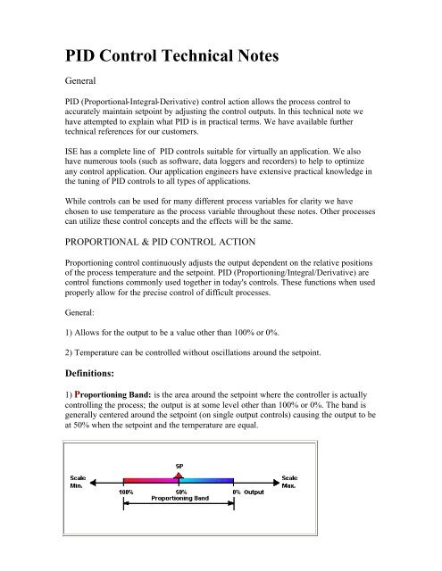
<strong>PID</strong> <strong>Control</strong> <strong>Technical</strong> <strong>Notes</strong>General<strong>PID</strong> (Proportional-Integral-Derivative) control action allows the process control toaccurately maintain setpoint by adjusting the control outputs. In this technical note wehave attempted to explain what <strong>PID</strong> is in practical terms. We have available furthertechnical references for our customers.ISE has a complete line of <strong>PID</strong> controls suitable for virtually an application. We alsohave numerous tools (such as software, data loggers and recorders) to help to optimizeany control application. Our application engineers have extensive practical knowledge inthe tuning of <strong>PID</strong> controls to all types of applications.While controls can be used for many different process variables for clarity we havechosen to use temperature as the process variable throughout these notes. Other processescan utilize these control concepts and the effects will be the same.PROPORTIONAL & <strong>PID</strong> CONTROL ACTIONProportioning control continuously adjusts the output dependent on the relative positionsof the process temperature and the setpoint. <strong>PID</strong> (Proportioning/Integral/Derivative) arecontrol functions commonly used together in today's controls. These functions when usedproperly allow for the precise control of difficult processes.General:1) Allows for the output to be a value other than 100% or 0%.2) Temperature can be controlled without oscillations around the setpoint.Definitions:1) Proportioning Band: is the area around the setpoint where the controller is actuallycontrolling the process; the output is at some level other than 100% or 0%. The band isgenerally centered around the setpoint (on single output controls) causing the output to beat 50% when the setpoint and the temperature are equal.
On (2) two output controls (i.e.: heat/cool) there are two proportioning bands. One is forheating and one is for cooling. In this case the bands generally end at the setpoint asshown below.Proportioning bands are normally expressed in one of three ways:• As a percentage of full scale• As a number of degrees (or other process variable units)• Gain which equals 100%/proportioning band% (example PB% = 5; Gain = 20)If the proportioning band is to narrow an oscillation around the setpoint will result. If theproportioning band is to wide the control will respond in a sluggish manner, could take along time to settle out at set point and may not respond adequately to upsets.Manual Reset: Virtually no process requires precisely 50% output on single outputcontrols or 0% output on two output controls. Because of this many older control designsincorporated an adjustment called manual reset (also called offset on some controls). Thisadjustment allows the user to redefine the output requirement at the setpoint. Aproportioning control without manual or automatic reset (defined below) will settle outsomewhere within the proportioning band but likely not on the setpoint. Some newercontrols are using manual reset (as a digital user programmable value) in conjunctionwith automatic reset. This allows the user to preprogram the approximate outputrequirement at the setpoint to allow for quicker settling at setpoint.Automatic Reset (Integral): Corrects for any offset (between setpoint and processvariable) automatically over time by shifting the proportioning band. Reset redefines theoutput requirements at the setpoint until the process variable (temperature) and thesetpoint are equal. Most current controls allow the user to adjust how fast reset attemptsto correct for the temperature offset. <strong>Control</strong> manufacturers display the reset value asminutes, minutes/repeat (m/r) or repeats per minute (r/m). This difference is extremelyimportant to note for repeats/ minute is the inverse of minutes or minutes/ repeat). Thereset time constant must be greater (slower larger number m/r smaller number r/m) thanthe process responds. If the reset value (in minutes/repeat) is to small a continuousoscillation will result (reset will over respond to any offset causing this oscillation). If thereset value is too long (in minutes/ repeat) the process will take to long to settle out at
setpoint. Automatic reset is disabled any time the temperature is outside theproportioning band to prevent problems during startup.Below is an example of a single output (heat only temperature control) with a 10%proportioning band and a setpoint of 400. Note how reset shifts the proportioning bandwhen the temperature (PV) enters the proportioning band.
Reset stops moving the proportioning band as soon as the setpoint and PV are equal. Inthe above example reset determined approximately 38% output is required to maintainsetpoint. Stable control is achieved and the temperature matches the setpoint of 400.Rate (Derivative): Shifts the proportioning band on a slope change of the processvariable. Rate in effect applies the "brakes" in an attempt to prevent overshoot (orundershoot) on process upsets or startup. Unlike reset rate operates anywhere within therange of the instrument. Rate usually has an adjustable time constant and should be setmuch shorter than reset. The larger the time constant the more effect rate will have. Toolarge of a rate time constant will cause the process to heat too slowly. Too short and thecontrol will be slow to respond to upsets. The time constant is the amount of time anyeffects caused by rate will be in effect when rate is activated due to a slope change.Self Tuning /Adaptive Tuning / Pre-TuningMany control manufactures provide various facilities in their controls that allow the userto more easily tune (adjust) the <strong>PID</strong> parameters to their process. Below is a description ofsame.Tuning On Demand with Upset: This facility typically determines the <strong>PID</strong> parametersby inducing an upset in the process. The controls proportioning is shut off (on-off mode)and the control is allowed to oscillate around a setpoint. This allows the control tomeasure the response of the process when heat is applied and removed (or cooling isapplied). From this data the control can calculate and load appropriate <strong>PID</strong> parameters.Some manufactures perform this procedure at setpoint while others perform it at othervalues. Caution must be excersized for substantial swings in the process variable valueswill likely occur while the control is in this mode.Adaptive Tuning: This mode tunes the <strong>PID</strong> parameters without introducing any upsets.When a control is utilizing this function it is constantly monitoring the process variablefor any oscillation around the setpoint. If there is an oscillation the control adjusts the<strong>PID</strong> parameters in an attempt to eliminate them. This type of tuning is ideal for processeswhere load characteristics change drastically while the process is running. It cannot beused effectively if the process has externally induced upsets for which the control couldnot possibly tune out. For example: A press where a cold mold is inserted at some cyclicrate could cause the <strong>PID</strong> parameters to be adjusted to the point where control would betotally unacceptable.
Some manufactures call Tuning on demand Self Tune, Auto Tune or Pre-Tune. Adaptivetuning is sometimes called Self Tune, Auto Tune or Adaptive Tune. Since there is nostandardization in the naming of these features questions must be asked to determine howthey operate.General <strong>Control</strong> TypesON-OFF CONTROL ACTIONOn-Off control is the most basic form of temperature control.1) Changes output only after temperature crosses the setpoint.2.) Should only used on non-critical applications, The process temperature neverstabilizes at the setpoint due to process inertia.3.) Also used in alarms and safety circuits.4.) Most <strong>PID</strong> controls operate in this mode if the proportioning band is set to "0".Time Proportioning <strong>Control</strong>s1.) Vary the output by cycling a relay, SSR or logic voltage on and off.2.) Proportions by varying the On Time versus Off Time.3.) Usually include a parameter such as Cycle Time which is the total of the On Time andthe Off Time. Example of its operation is as follows: With a Cycle Time of 10 seconds ifthe control decides it wants 42% heat applied to the process the output would be On for4.2 seconds and Off for 5.8 seconds giving an effective output of 42%.Linear Output <strong>Control</strong>s1.) Provides a DC voltage or current output related to the required output demand. Forexample: If the control has an output range of 4-20 mA and decides it wants 50% powerto the process the control would output 12.0 mA2.) Normally connected to an SCR Power control or other solid state device. The powerhandling device then converts this signal to a relative power output.Closed Loop Valve Motor <strong>Control</strong>s1.) These controls are used in conjunction with motor actuators in gas heatingapplications. The control has (2) outputs (typically relays) one for clockwise rotation andone for counter clockwise rotation.2.) Feedback as to motor position is provided by a potentiometer attached to the motor.
Open Loop Valve Motor <strong>Control</strong>s1.) These controls are used in conjunction with motor actuators in gas heatingapplications. The control has (2) outputs (typically relays) one for clockwise rotation andone for counter clockwise rotation.2.) No feedback as to motor position is provided. The user enters a value for motor traveltime in the control. This allows the control to determine how long to operate the motor ineither direction.High & Low Limit <strong>Control</strong>s1.) Usually used as safety devices upon the failure of the primary control device or someother failure in the system.2.) Once the process variable goes through the limit setpoint the controllers outputswitches. The output will not revert back to normal until the process variable returns to asafe value and a reset button is pressed.3.) Most insurance companies require FM approved limit devices on certain applicationsparticularly on gas fired and on applications that are left unattended.4.) For complete safety a separate sensor and contactor is required. On electricapplications utilizing SCR power controls a contactor connected to the incoming powerof the SCR should be used to protect against SCR failure.Copyright © 1996 by ISE, Inc. All rights reserved.Contact InformationINSTRUMENT SERVICE & EQUIPMENT, INC.10100 Royalton Rd. - Cleveland, OH 44133 USATel: (440) 237-3200 - Fax: (440) 237-1744 - http://instserv.comToledo, Oh Area Office:417 Tomahawk Drive - P.O. Box 737 - Maumee, Oh 43537Phone: 419-893-3330 - FAX: 419-893-2151