VF-200 User Guide 2-0 (1).pdf - DV Signage
VF-200 User Guide 2-0 (1).pdf - DV Signage
VF-200 User Guide 2-0 (1).pdf - DV Signage

You also want an ePaper? Increase the reach of your titles
YUMPU automatically turns print PDFs into web optimized ePapers that Google loves.
DC 12V<br />
RS - 232<br />
Normal<br />
Test<br />
Volume<br />
VideoFlyer 20”<br />
Model : <strong>VF</strong>-<strong>200</strong><br />
<strong>User</strong> <strong>Guide</strong><br />
Introduction<br />
The following is intended as a guide to installation and initial setup of the standard 20”<br />
VideoFlyer, an Internet connected digital video player and display.<br />
This <strong>Guide</strong> covers:<br />
• Mounting information: How to attach the unit to a fixture<br />
• Installation of a Compact Flash (CF) memory card<br />
• Power: On/off, power considerations<br />
• Setup using the optional 8 segment touch screen<br />
• Operation: How to play video on VideoFlyer<br />
Preparation<br />
It is advisable to do a quick check that the display is working properly prior to installation. Simply<br />
install the CF card as explained below and then power on. If the unit powers up then proceed with<br />
installation.<br />
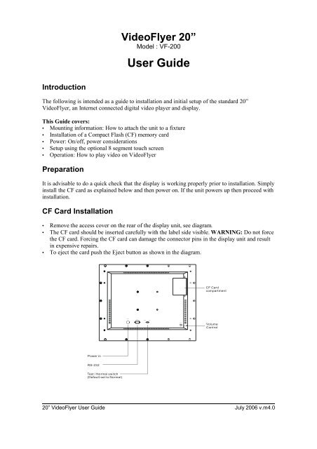
CF Card Installation<br />
• Remove the access cover on the rear of the display unit, see diagram.<br />
• The CF card should be inserted carefully with the label side visible. WARNING: Do not force<br />
the CF card. Forcing the CF card can damage the connector pins in the display unit and result<br />
in expensive repairs.<br />
• To eject the card push the Eject button as shown in the diagram.<br />
CF Card<br />
compartment<br />
Volume<br />
Control<br />
Power in<br />
RS-232<br />
Test / Normal switch<br />
(Default set to Normal)<br />
20” VideoFlyer <strong>User</strong> <strong>Guide</strong> July <strong>200</strong>6 v.m4.0
Mounting<br />
The housing is of metal construction and has 4 threaded mounting holes on the rear of the<br />
housing, (see diagram below).<br />
Points to note:<br />
Mounting: It is recommended to use a mounting bracket that allows the display to be set to the<br />
ideal viewing angle.<br />
Sound: Speakers are on the bottom of the housing, ensure they are not covered.<br />
100mm (A)<br />
75mm (B)<br />
50mm (C)<br />
The diagram shows the mountin holes used on the<br />
VideoFlyer Range. The 20" model has both holes Ref A<br />
and B available.<br />
50mm (C)<br />
75mm (B)<br />
100mm (A)<br />
Ref<br />
A<br />
B<br />
C<br />
Standard<br />
VESA<br />
VESA<br />
Digital View<br />
Use mounting holes reference A or B, ie 100mm and<br />
75mm spacing<br />
Screws are 4mm diameter<br />
Power<br />
The display system is supplied with an AC to DC power adaptor. This should be connected to the<br />
mains.<br />
The power switch is mounted on the back of the housing, ensure the unit is switched on. If you<br />
have a custom version with no power switch on the housing then the unit will power on<br />
immediately it is connected to the power supply. If it does not then please check the power supply.<br />
Notes:<br />
Power input: 12V DC, 6A (min.)<br />
Power cord: You need an AC power cord that is certified for the country or region you are<br />
located. Using an improper power cord might cause severe damage to your unit.<br />
20” VideoFlyer <strong>User</strong> <strong>Guide</strong> July <strong>200</strong>6 v.m4.0
Display Setup (touch screen versions only)<br />
1. The touch screen, if fitted, has 8 touch segments (buttons) which can be programmed with <strong>DV</strong><br />
Studio software to perform in VCD player mode or specific track select functions.<br />
2. Config mode<br />
To enter the Config. Mode, holding the button 8 and power up.<br />
Button 8<br />
Holding the button<br />
Power on<br />
VOLUME 14 VER 4.10<br />
Y M D H M S<br />
<strong>200</strong>4 .10 .12 15 : 48 : 44<br />
ID NO: 0712<br />
DATA LOGGING: ON<br />
OSD: ON<br />
SAVE AND EXIT<br />
Config. Mode menu<br />
The volume setting can be adjusted when the config. mode is enabled.<br />
Press button 8 + power up<br />
Press button 7<br />
Press button 6<br />
Press button 8<br />
: Config. mode enable.<br />
: Increase the volume level / Save<br />
: Decrease the volume level / Save<br />
: Select<br />
20” VideoFlyer <strong>User</strong> <strong>Guide</strong> July <strong>200</strong>6 v.m4.0
Operation<br />
CAUTION: Never connect or disconnect parts of the system when the system is powered up as<br />
this may cause serious damage.<br />
All the features described in the following points can be set by the <strong>DV</strong> Studio software. See <strong>DV</strong><br />
Studio <strong>User</strong> <strong>Guide</strong> for more details.<br />
1) Autoplay, Manual Play at power startup<br />
Insert CompactFlash Card containing the captured MPEG-1/MPEG-2 files.<br />
Turn on the Remote Flyer.<br />
Set power switch to ON position. The power LED lights up to confirm power is being<br />
supplied to system.<br />
The option of AutoPlay or manual play of tracks at powering up of unit is selected in the<br />
<strong>DV</strong> Studio software when writing the MPEG files on to CompactFlash Card.<br />
In Auto play mode the first track of the Playlist set in <strong>DV</strong> Studio software will<br />
automatically play after power up.<br />
In Manual Play mode after power up press any button and the first track of the Playlist set<br />
in <strong>DV</strong> Studio software will play.<br />
2) Auto-loop playing of video tracks<br />
Tracks can be set by the <strong>DV</strong> Studio software to play in a continuous loop, individually or<br />
in sequence one after another.<br />
3) Simple playback<br />
The simple playback is only applicable in all remote flyer and remote player. Customer<br />
just copying all those MPEG files (.mpg) to the Compactflash card and make sure the<br />
project (.prj) and playlist (.pll) files had been removed. The remote flyer will playback the<br />
MPEG file(s) automatically in ALPHABETICAL order of its filename. For still picture<br />
MPEG file, the play time can be defined by the last digit of the filename. (For example,<br />
Apple5.mpg – where “5” means play the track for 5 seconds.)<br />
20” VideoFlyer <strong>User</strong> <strong>Guide</strong> July <strong>200</strong>6 v.m4.0
SAFETY NOTICES<br />
WARNING : TO REDUCE THE RISK OF FIRE OR ELECTRIC SHOCK, DO NOT<br />
EXPOSE THIS APPARATUS TO RAIN OR MOISTURE<br />
RISK OF ELECTRIC SHOCK<br />
DO NOT OPEN<br />
Whilst care has been taken to provide as much detail as possible for use of this product it cannot<br />
be relied upon as an exhaustive source of information. This product is for installation by suitably<br />
qualified persons who understand the nature of the work they are doing and are able to take<br />
suitable precautions and produce a result that is safe and meets regulatory requirements.<br />
There are no user serviceable parts in this product.<br />
Do not touch HIGH VOLTAGE PART of the lamp cables while turn on. Customer will be<br />
in danger of an electric shock.<br />
This sign has a meaning that user will be injured by himself, if the user makes a mistake<br />
in operations.<br />
IMPORTANT SAFETY INSTRUCTIONS<br />
Precautions for use, read the following instructions:<br />
Keep these instructions.<br />
Follow all instructions and heed all warnings.<br />
Do not use this product near water, or environments where it can get wet.<br />
Keep clean only with dry cloth.<br />
Do not block any ventilation openings.<br />
Do not install near any heat sources such as radiators, heat registers, stoves, or other<br />
apparatus (including amplifiers) that produce heat.<br />
Do not defeat the safety purpose of the grounding-type plug. A grounding type plug has<br />
two blades and a third grounding prong. The third prong are provided for your safety. If<br />
the provided plug does not fit into your outlet, consult an electrician for replacement of<br />
the obsolete outlet.<br />
Protect the power cord from being walked on or pinched particularly at plugs,<br />
convenience receptacles, and the point where they exit from the apparatus.<br />
Only use attachments/accessories specified by the manufacturer.<br />
Unplug this apparatus during lightning storms or when unused for long periods of time.<br />
Refer all servicing to qualified service personnel. Servicing is required when the<br />
apparatus has been damaged in any way, such as power-supply cord or plug is<br />
damaged, liquid has been spilled or objects have fallen into the apparatus, the<br />
apparatus has been exposed to rain or moisture, does not operate normally, or has<br />
been dropped.<br />
Power Supply Replacement and Services Information: When replacement of power<br />
supply is required, please return it to the nearest service center.<br />
20” VideoFlyer <strong>User</strong> <strong>Guide</strong> July <strong>200</strong>6 v.m4.0